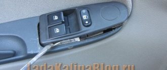
The glass lift buttons of Kalina have a much nicer appearance and a more convenient shape. Therefore, many VAZ 2110 owners decide to change the standard ESP keys to Kalinovsky ones. How difficult is it to make this replacement?
There are 2 types of Kalinovsky ESP keys: low-current (multiplex) and power.
To install low-current ESP keys, you will need to install an electrical package control module/electric package controller (2170-3763040).
This will also allow you to close the doors and windows of the car with a key or key fob, there will be a two-stage door opening, and the ability to control electric mirrors and door locks from the glass lift module.
If you use ESP power keys, then everything is simpler; no additional control units are required. You just need to connect the keys correctly.
Remember the main thing: power keys are produced by Avar, and multiplex keys are produced by Itelma.
It is necessary to purchase an ESP key for a VAZ 1118, sample AVAR 1118-3709613-10 (921.3709). It has power contacts, the socket of which exactly fits the 10.
Their cost is about 30 - 50 hryvnia.
It will not be possible to install 1118-3763080 - a new module with 4 ESP keys, central locking (CL) and mirror adjustment, since they are all multiplex. And this is reasonable, since it is difficult to stretch such a mass of power wires through the door.
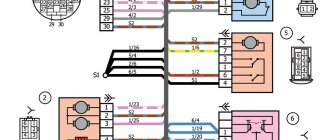
Connection diagram for ESP module for Kalina buttons and pinout
connection diagram for the Kalinamotor ESP module in the driver's door
- mass (only 1 can be combined inside)
- +12V for driver's window
- weight
- +12V for passenger window
- absent
- socket module ESP viburnum dimensions
- to the 3rd leg of the key in the passenger door
- to the 6th leg of the key in the passenger door
- Central lock key:
- socket of central locking module ESP Kalina closing
- weight
- absent
- dimensions
- backlight weight
- absent
- opening
You can purchase the Kalinovsky module and ESP control keys in online stores, and if you modify the VAZ-1118 control module with electric window lifts, you can install 4 keys. You will simply need to connect the module 1118-3709810-10 with 2 piece keys 2170-3763040. So, the ESP power module of 4 keys and central locking is ready!
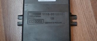
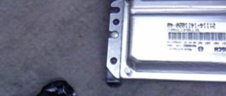
The electrical package control unit (pictured below) Kalina Lux does not work. Or rather, it does not respond to my presses. It is illuminated, when I press the buttons, click, I hear a single short sound in the area of the speedometer/heater (you can hear it in the video below). This thing appeared in the morning, I walked away for an hour, everything worked. By evening everything stopped responding again and it’s been like this for the whole day. Neither the central locking, nor the mirrors, nor the power windows respond to my presses.. What's the matter? I disconnected the terminal for 15 minutes, it didn’t help, the alarm was starline.
Causes of breakdowns
The cause of the DS malfunction may be:
- poor contact in the DS connector or its complete absence;
- violation of the integrity of the wiring, the wires oxidize and rust over time;
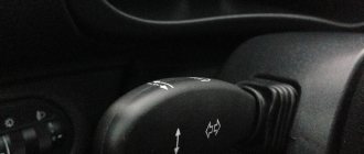
- contamination on sensitive elements;
- sensor element malfunction.
The first three reasons can be corrected without replacing the DS; in the latter case, the device must be changed.
Checking the cleanliness of the connector
Kalina ESP buttons on VAZ 2110
There are two types of Kalinovsky ESP buttons: low-current (multiplex) and power. To install low-current ESP buttons, you will need to install an electrical package control unit/electrical package controller (2170-3763040). This will also allow you to close the doors and windows of the car with the key (the control is built into the key), there will be a two-stage door opening, and the ability to control electric mirrors and door locks from the power window unit. In the case of ESP power buttons, everything is much simpler, no additional control units are required. You just need to connect the buttons correctly.
Video “Replacing the speed sensor”
This video demonstrates how to replace a speed sensor with your own hands (the author of the video is Alexandr V).
Schematic electrical diagrams, connecting devices and pinouts of connectors
The speed sensor is an element of the vehicle's electronic control system. It depends on its readings how much fuel will be supplied, how much air will bypass the throttle valve when idling, and what the speedometer readings will be.
The speed sensor of a VAZ car is based on the use of the Hall effect, that is, a stream of pulses is transmitted from the device to the car's ECU, the frequency of which is proportional to the speed of the car. Auto electronics, analyzing incoming data, selects the required idle speed and sends a signal to a device that regulates the engine idle speed, which optimizes the composition of the air-droplet mixture entering the combustion chamber, bypassing the throttle valve.
During a distance of one kilometer, the speed sensor transmits over 6000 pulses to the ECU. Based on the parameters of the time analysis of inter-pulse signals, the on-board computer transmits data to the dashboard, thereby determining the speedometer readings.
As in many other cars, the VAZ speed sensor is located in the upper part of the gearbox housing, not far from the engine oil level dipstick. You can get to it from two sides: from above, by opening the hood and disconnecting the adsorber, and from below, using the inspection hole for convenience.
Electrical equipment Lada Kalina
KALINA
repair
electrical equipment
Car electrical diagram
Diagnostics of electrical equipment of VAZ 1117 Kalina. VAZ 1118 Kalina car diagrams, wiring, electric motors VAZ 1119 Lada Kalina.
Electrical circuit diagram of a car Repair of components of the electrical circuit diagram Lada Kalina do-it-yourself repair Lada electrical equipment, design and maintenance
Electrical diagram of a Lada Kalina car: 1 - right headlight; 2 — hood open sensor; 3 — sound signal; 4 - starter; 5 - battery; 6 - generator; 7 — windshield wiper gear motor; 8 — left headlight; 9 — right front door power window switch; 10 — motor-reducer for window lifter of the right front door; 11 — connection blocks to the right front speaker; 12 — electric drive for locking the lock of the right front door; 13 — windshield washer electric motor; 14 — ambient temperature sensor; 15 — block for connecting the wiring harness of the engine control system; 16 — electric drive for locking the left front door lock; 17 — brake fluid level sensor; 18 — connection blocks to the left front speaker; 19 — power window switch for the right front door, located on the driver’s door; 20 — left front door power window switch; 21 — door lock switch; 22 — motor-reducer for window lifter of the right front door; 23 — mounting block; 24 — control unit for the automobile anti-theft system; 25 — security alarm control unit; 26 — instrument cluster; 27 — right side turn signal; 28 — glove box lighting lamp; 29 — switch for the glove compartment lighting lamp; 30 — brake signal switch; 31 — ignition switch with transponder of the automobile anti-theft system; 32 — control unit for external lighting, instrument lighting and headlight beam direction control; 33 — steering column switch; 34 — left side direction indicator; 35 — connection blocks to the right rear speaker; 36 — electric drive for locking the right rear door; 37 — rear window heating switch; 38 — reverse lock switch; 39 — alarm switch; 40 — heater fan operating mode switch; 41 — additional resistor of the heater fan electric motor; 42 — heater fan electric motor; 43 — connection blocks to the left rear speaker; 44 — electric drive for locking the left rear door; 45 — electric fuel pump with fuel level indicator sensor; 46 — reverse light switch; 47 — parking brake warning switch; 48 — cigarette lighter; 49 — reverse lock solenoid; 50 — connection blocks to the head unit of the sound reproduction system; 51 — backlight lamps for the ventilation and heating system control unit; 52 — electric power steering control unit; 53 — interior lamp; 54 — right rear light; 55 — electric drive for locking the trunk lock; 56 — trunk light switch, built into the trunk lid lock; 57 — license plate lights; 58 - additional brake signal; 59 — rear window heating element; 60 — trunk light; 61 - left rear light. This diagram does not show the connection points and wiring harness terminals.
Signs of a malfunctioning speed sensor
If the DS is faulty, then the following signs appear:
- incorrect speedometer readings, the needle moves chaotically, complete speedometer failure;
- increased fuel consumption;
- The power steering refuses to work;
- the power unit check sign is on;
- The car odometer does not show mileage;
- the arrow indicating the fuel level fluctuates, making it impossible to correctly determine the level;
- the engine does not pull or has lost throttle response;
- The engine stalls at idle.
The listed symptoms can be caused by a breakdown of other devices (the author of the video is Autoelectrics HF).
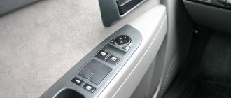
Window control unit Kalina
Sometimes, during the run-in phase of the car, the power window control unit begins to malfunction; Kalina is no exception in this case. Often such a block simply refuses to move the rear or front windows in space. There are many reasons for this. The most common are assembly defects and operating errors. In any of these cases, you can independently diagnose Kalina's power windows.
Return to contents
Analysis of the current situation
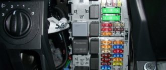
Drivers with basic skills in working with tools will understand what needs to be done if the power window on a Kalina does not work. First you need to check the installed fuse and relay in the mounting block. The diagram supplied with the official vehicle operating instructions designates the indicated elements as F2 (25 A) and K2, respectively. If the problem could not be detected, then the inspection is transferred to the terminals of the electric motor of the Lada Kalina.
To do this, you need to carefully remove the door trim. A multimeter or a 12 V test lamp will help you find out the exact voltage level. If the terminals show no voltage, you need to check the most likely culprits of a possible malfunction. In the first place is the window lift button, followed by wiring and connectors.
The absence of noticeable signs of malfunction here requires checking the power window control unit. It is important to make one reservation: for a vehicle presented in the luxury configuration, it is necessary to inspect the central body electronics unit (CBEC). The fault diagnosis procedure ends with a conclusion about the passage of current to the electric motor or its absence.
If there is current, but no movement of the Kalina windows is observed, a possible cause should be looked for in the areas described below:
- glass distortion;
- glass clamp;
- the window lift cable is torn or frayed;
- wear of the glass drive motor shield;
- drive motor shield retraction;
Further actions are based on the nature of the identified malfunction. In the worst case scenario, replacing a broken or worn part will take 70 minutes. It all depends on the experience of the car owner and the actual breakdown. For example, removing and installing a new relay will take about an hour.
Return to contents
Vehicle Maintenance
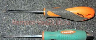
It is recommended to replace any parts in the car only with original ones. Compliance with this requirement will eliminate subsequent unscheduled repairs. If Kalina's power window button requires servicing, then first you will need to find the necessary tools.
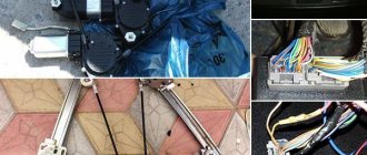
Using 2 small flathead screwdrivers, you need to remove the block from the grooves. Direct replacement is carried out without sudden movements, so as not to break fragile elements. As soon as it becomes possible to get to the wiring, you need to get rid of the plug with equal care. This can be done with little physical effort. A latch is used to disconnect the second plug.
After the glass power supply is removed, it must be inspected. The presence of any mechanical damage indicates the need for mandatory replacement. Even in-depth repairs will not help restore its functionality. Before installing a new unit, another check must be carried out. Its relevance increases when it comes to replacing a relay.
After removing the faulty part, you should manually check all connecting fasteners and wires. Traces of charring or damage are a sign that the Kalina power window button most likely needs to be replaced. If this is not done, then the need for repeated repairs will arise within 2-3 months. This is due to the increased load on the Lada window regulator.
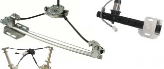
Removal instructions
The device will be dismantled starting from the front windows. Before making repairs, you need to remove the defective unit, but first you need to dismantle the door trim.
Detailed instructions for dismantling the joint venture:
- First of all, you need to lift the glass all the way and fix it at the highest point with tape. It will be a right or left window regulator, it doesn’t matter.
- After this, using a 10mm wrench, you need to unscrew the two bolts that secure the glass itself. In addition, you will need to unscrew the screw on the inner handle of the lock.
- Then you need to disconnect the system motor and wiring from the power circuit.
- Unscrew the nuts on the mechanism, there are eleven in total, and dismantle the joint venture.
- Now let's move on to the rear joints. In this case, the dismantling procedure is almost identical - first, the glass must be lifted up all the way and fixed.
- Using a size 8 wrench, you need to unscrew the three nuts securing the assembly. Then, using a 10mm wrench, unscrew two screws and three more nuts. After completing these steps, you can dismantle the unit through the corresponding hole in the bottom of the door. Having removed the joint venture, you need to assess its condition. If the problem can be solved without replacing the mechanism, then repair the device; if the malfunction is “lethal”, for example, the window lift motor or gear has failed, then installation of a new mechanism will be required.
Diagnostics
Checking the controller can be done in several ways; we recommend that you familiarize yourself with each of them in more detail. For the first two methods you will need a voltmeter.
- First, the sensor must be removed. Find its installation location, disconnect the connected connector, unscrew the fixing nut and remove the device from the mounting location.
- Then take a voltmeter and figure out the pinout of the connector. The connector has three contacts, the first of which is usually a positive contact, the second is an output signal, and the third is a negative contact. One of the tester probes should be connected to contact number 2, and the second probe should be grounded - connected to the engine body or car body.
- Afterwards, you need to rotate the controller to determine whether there are pulses in the operating cycle and measure the output voltage. To do this, you need to install a piece of pipe on the sensor axis and rotate the device at a speed of approximately 3-5 km/h. The voltage and frequency in the tester depend on the rotation speed of the controller (the author of the video is Artem Kulzhanov).
The second diagnostic option is performed without dismantling the sensor:
- You need to put the car on a jack. You need to jack up the front of the car so that one of the wheels is hanging out and not in contact with the ground.
- After this, the tester probes must again be connected to the contacts on the device connector.
- The hanging wheel must be rotated and at the same time monitor the readings on the tester display. If, as a result of rotation, voltage and frequency appear, measured in hertz, then this indicates the operability of the device.
There is another checking option; to perform it you will need a light bulb or control.
Diagnostics is performed as follows:
- First of all, you should disconnect the plug and wiring from the sensor.
- Using the control, you will need to find the plus and minus, before that you need to turn on the ignition.
- Next, as in the previous method, you need to put the front of the car body on a jack and hang one wheel.
- Now you should connect the control pin to the pulse contact of the sensor (usually it is the middle one) and rotate the wheel by hand. If at the same time the minus lights up on the control panel, this indicates that the device is working. Alternatively, instead of a control, you can use a light bulb with a connected wire, one of which is connected to the battery, and the second to the signal connector. If the light begins to blink when the wheel rotates, then the controller is working (video shot by Alex Kov).
How to check the VAZ speed sensor
A failed speedometer sensor in a VAZ car is easily determined - in this case, the speedometer stops working, and it may also show some signs of life, but display incorrect information.
Using a tube, pliers or other available tools, rotate the sensor axis. In this case, you should see the voltmeter readings changing: the higher the speed, the higher the voltage (from 0.5 to 10 V). If this does not happen, the sensor requires replacement.
Power supplies
In the on-board network of the model we are considering, all pantographs operate at a voltage of 12 V and consume direct current. The electrical circuit for their switching is single-wire.
The wiring diagram contains components that are divided into 4 categories:
- energy sources;
- its consumers;
- protective components;
- sensors
The “representatives” of the first two groups, with their negative terminals, are connected via wires to the body, which appears as “ground”. If we talk about the sources, then there are two of them in the car: the battery and the generator set. When the engine is running, the generator produces power, and when the engine is stopped, the battery is “occupied” with supplying the current collectors with electricity. The generator unit recharges the battery during its operation.
The principle of operation of the generator is quite simple. By means of a belt drive from the rotating crankshaft pulley, the rotor of the generator unit is driven in a circular motion. Thus, alternating current is generated, which is converted into direct current by means of a rectifier module. Over time, the rotor shaft bearings become unusable. They initially contain a lubricant, which gradually loses its properties. The stator of the device has a three-phase winding and is connected to the cover with four studs. There is also a voltage regulator in the generator unit. He monitors that this indicator is within 14.5-15.0 Volts. Note that the rotation ratio of the motor to the generator is 1:2.4. The maximum generated current is 85A.
Stove damper on Kalina
Replacing the Kalina steering rack video
Replacing antifreeze in Kalina
Let's take a closer look at the rotor. Its field windings are connected by soldering to copper rings, which are located on the element shaft and provide contact. The voltage regulator is a non-separable part and if it breaks, it requires no alternative replacement. To protect the network from voltage surges that occur at the moment of ignition, a special capacitor is connected between the positive valve and the ground terminal.
When the motor is stopped, the battery supplies power to all required pantographs. This device makes it possible to start the motor. The electrical circuit of the Lada Kalina car provides for a parallel electrical connection of the battery and the generator set.
The negative terminal of the battery is connected exclusively to the body “mass” contact, and the positive terminal is connected to the corresponding “B+” terminal present on the generator.
Do not remove the battery while the engine is running. This action will lead to a drop in the mains voltage, which will lead to the failure of expensive pantographs.
Replacing a car speed sensor
As for its location, look for the DS in the engine compartment in close proximity to the exhaust manifold. To be honest, the place where it is installed cannot be called ideal. While the car is running, the manifold heats up. The sensor wires rub against it, which over time leads to malfunctions and short circuits. Therefore, experts recommend that the first step is to properly insulate the wiring, and also use some kind of clamps so that the wires do not come into contact with the collector. This significantly extends its service life.
If the check shows that the DS is faulty, it needs to be replaced. Repairing sensors and similar small electronic devices is a thankless task. In a garage environment, this is unlikely to be possible, and the only thing that can be done is to clean the contacts from oxidation (this can be a problem).
It doesn’t matter whether you have an injection car or a carburetor with a Europanel - the connection of the speed sensor to the instrument cluster is identical.