On Priora, the electrical circuit differs from the usual electrical equipment of AvtoVAZ. Let's take a closer look at it. The Priora electrical circuit has a single-wire electrical circuit. The negative terminals of consumers and power supplies are connected to ground. The car body carries the function of the second wire.
As for the electrical circuits of the engine control system, they have a multi-wire system. They are connected to ground through a special control unit.
The electrical circuit on the Priora has four main harnesses: the instrument panel harness, the engine control harness, the front and rear harnesses. All of them are connected to each other using plug connectors, which are located under the dashboard on the left side near the fuses.
The rear harness and the dashboard harness are connected to the control unit using a plug. In addition to the above described tourniquets, other tourniquets can also be used. They connect additional equipment. Below is a more detailed description of the electrical circuit.
Air conditioning systems
One of the consumers is a heating device. It is part of the climate control system. A control controller works with this system. The work is automatic. The driver only sets certain parameters.
On cars, the electrical circuit of a VAZ Priora may contain air conditioning systems. After pressing the button, the relay is activated, the compressor is turned on, power is supplied to the electromagnetic clutch, and the pump is turned on. The air conditioning turbocharger begins to rotate, creating pressure, and begins to regulate refrigerant through the system.
parking lights
For example, the electrical circuit of a Lada Priora station wagon has the function of both automatic and manual activation of side lights. The activation itself occurs after turning the handle for the side lights and headlights on the dashboard. The contact is triggered and the lights turn on.
The circuit contains fuses that serve to protect against overvoltages and short circuits. Power is supplied to a lamp located on the dashboard. To adjust the brightness of the lights, a special regulator located on the lighting control module is used.
The headlight design of the Priora differs from other cars. The electrical circuit of the VAZ Priora contains a light sensor, as well as a lighting control unit. After turning on the ignition and the lighting control button, the electronic unit responsible for lighting control is activated.
If there is not enough light outside, the unit receives a signal from a sensor located on the windshield. There is also a rain sensor there. After receiving such a signal, the electronic control unit supplies power to the electromagnetic relay coil. Power is supplied to the headlights.
Instrument cluster block diagram
| № | Decoding |
| 1 | Electric power steering |
| 2 | Emergency gang control VAZ-2170 |
| 3 | Connection to oil pressure sensor |
| 4 | Parking brake indicator light |
| 5 | Electronic anti-theft device |
| 6 | Airbag control module |
| 7 | External lighting switch |
| 8 | Right turn signal indicator and doubler |
| 9 | Left turn signal indicator and backup |
| 10 | Engine control unit |
| 11 | Disabling the passenger's front airbag |
| 12 | Seat belt warning light |
| 13 | ABS brake system unit |
| 14 | Steering column switch button |
| 15 | Brake expansion tank indicator |
| 16 | ABS safety control module |
| 17 | Main beam headlight control unit |
| 18 | Shield backlight module |
| 19 | General disadvantage of the device |
| 20 | Constant positive battery terminals |
| 21 | Ignition switch contact |
| 22 | Fuel flow meter |
| 23, 24 | Steering wheel turn switches |
| 25,26 | Overboard temperature sensors |
| 27 | Fuel sensor VAZ-2170 |
| 28 | Speed sensor |
| 29 | Coolant temperature sensor |
| 30 | Tachometer signal |
| 31 | Shield diagnostics |
| 32 | Generator Regulator Relay Terminal |
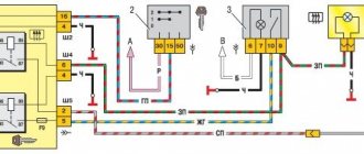
Electrical connection diagram for heater wiring harness PRIORA 21723
- heater wiring harness block to the front wiring harness block;
- air mixing gearmotor;
- evaporator temperature sensor;
- electric fan 2172;
- speed controller;
- recirculation gearmotor.
Parking system sensor diagram 2172-3724248
1,2,3 – parking system sensors; 4 – block of the wiring harness of the parking system sensors to the block of the rear wiring harness.
Rear license plate light pinout
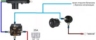
1. Supply voltage to the lights illuminating the rear number 2,3. Priora 4 license plate lamps. Electric trunk lid locking motor
Window lifters
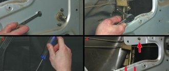
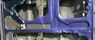
As for the power windows, the electrical circuit on the Priora differs from other models. Control is carried out using a controller. Raising and lowering the windows is done by briefly pressing the button.
In Lada Priora hatchback cars, the electrical circuit has the peculiarity of supplying power directly to the electric window drive. The wire supplies power to the mirror control, heating, and also to the solenoid designed to lock the doors. The control is carried out by the controller.
Pinout for left front door
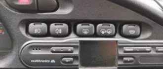
Most modern vehicles are equipped with a variety of driver comfort systems, one of which is the driver's door module.
The function of the button block located on the driver's door is to control the front windows and exterior mirrors, as well as the automatic locking of the car doors. The installed auxiliary left rear wiring harness (part number 21703-724551-90) comes complete with contact carriers made of electrically conductive materials.
| Contact no. | Decoding |
| 1 | Connector for the additional rear left harness to the rear harness |
| 2 | Rear left harness connector to front left speaker |
| 3 | Electric window lift |
| 4 | Armrest control module |
| 5 | Electric drive for locking the left front door |
| 6 | Left outer rear view mirror control chip |
Windscreen wipers
As for the windshield wipers of the Lada Priora, the electrical circuit in this case has a special programmable control unit. The circuit contains fuses to protect against overvoltages and short circuits.
The windshield wipers are turned on with a switch located near the steering wheel. The switch has eight positions, four of which are used to control the purifier. One position on the switch turns on the glass washer, the other two positions control the rear wiper. Another position is responsible for the disabled state of the windshield wiper.
Front Passenger Door Wiring Harness
The electrical wiring of the left and right front doors of the car differs in the additional control buttons for mirrors and power windows on the driver's door.
The factory original front passenger door wiring harness, part number 21703-3724550 -90, duplicates the power supply from the passenger door center front keypad.
There are 7 connectors coming out of the harness.
| Contact no. | Decoding |
| 1 | Connector of the right rear additional harness to the rear harness |
| 2 | Rear left harness connector to front speaker |
| 3 | Window lift motor |
| 4 | Electric window lift switch |
| 5 | electric front passenger door lock |
| 6 | Motor controls the position of the outer right mirror and its heating |
| 7 | Connector of the right rear additional harness to the rear harness |
One thought on “Electrical diagram of Lada Priora in detail”
These materials present in an extremely simple and accessible form a description of the maintenance and repair of VAZ Lada Priora cars in a step-by-step manner using ready-made spare parts in a garage workshop. Possible malfunctions have been studied and methods for eliminating them have been considered.
Schematic electrical diagrams, connecting devices and pinouts of connectors
The generator in cars is designed to generate electricity and charge the battery. If the normal operation of a car electric generator is disrupted, the battery begins to discharge and soon the car will stop starting completely - there is not enough battery charge. This device consists of a three-phase diode bridge, which, in turn, has 6 silicon diodes. Electrical voltage is created by the excitation of the rectifier at the moment when the rotor poles change under the stator windings. When the rotor rotates inside the machine stator, the poles of the rotor change. To increase the value of magnetic fluxes, the stator contains an electromagnetic exciting winding in the area of the magnetic cores. Marking and designation of wires:
- P - pink.
- F - purple.
- O - orange.
- B&W - black and white.
- KB - brown and white.
- CHG - black and blue.
- K - brown.
- H - black.
- B - white.
Connection diagram for the VAZ-2101 generator
Structurally, generator 2101 consists of the following main elements:
- The rotor is a moving part that rotates from the engine crankshaft. Has an excitation winding.
- The stator is the stationary part of the generator and also has a winding.
- Front and rear covers , inside of which bearings are installed. They have eyelets for attaching to the internal combustion engine. The back cover contains a capacitor necessary to cut off the alternating current component.
- Semiconductor bridge - called a “horseshoe” for its similarity. Three pairs of semiconductor power diodes are mounted on a horseshoe-shaped base.
- A pulley on which the VAZ-2101 generator belt is placed. The belt is V-shaped (on modern cars a multi-ribbed belt is used).
- The voltage regulator is installed in the engine compartment, away from the generator. But still it must be considered part of the structure.
- The brushes are mounted inside the generator and transmit the supply voltage to the field winding (on the rotor).
Rear license plate light pinout
According to traffic regulations, the state license plate illumination must always be in working order. For lighting, W5W incandescent lamps are connected, each with a power of 5 W.
The small wiring harness for the rear license plate light (harness serial number 2170-3724214) consists of wires with cream ends and is located in the luggage compartment. The operation of the entire lighting system depends on its quality. The harness responsible for the rear license plate illumination has 3 terminals:
| № | Decoding |
| 1 | Supplying voltage to the lights illuminating the rear number |
| 2,3 | License plate lamps |
| 4 | Electric tailgate lock motor |
Connection diagram for the VAZ-2107 generator
1 - battery; 2 - negative diode; 3 - additional diode; 4 - generator; 5 - positive diode; 6 - stator winding; 7 - voltage regulator; 8 — rotor winding; 9 — capacitor for suppressing radio interference; 10 — mounting block; 11 — battery charge indicator lamp in the instrument cluster; 12 - voltmeter; 13 — ignition relay; 14 - ignition switch.
Additional mounting block Priora
- F1 (15 A) – main relay and starter interlock circuit fuse;
- F2 (7.5 A) – fuse for the power supply circuit of the ECU (controller);
- F3 (15 A) – Priora fuel pump fuse;
- K1 – main relay;
- K2 is the place where the Priora fuel pump relay is located.
Attention!
The relay and fuse diagram may differ depending on the configuration and production date of the vehicle. Current diagrams of the mounting block are presented in the operating manual for the date of manufacture of the vehicle (download from the official website).
Let us remind you that on our website you can find detailed instructions for repairing the Lada Priora with your own hands.
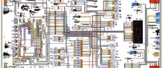
Electrical equipment diagram for a car such as VAZ-2170 Lada Priora 2004+. The Lada Priora is equipped with an injection 16-valve engine mod. located across the engine compartment. VAZ-21126-00 with a working volume of 1.6 liters. The engine is equipped with a distributed fuel injection system and an exhaust gas catalytic converter, structurally made in a single block with the exhaust manifold (catcollector). The body is load-bearing, all-metal, of welded construction, with hinged doors, front fenders, hood and trunk lid.
Instrument panel harness connection diagram
1, 2, 3 — instrument panel harness pads to the front harness; 4 — instrument panel harness block to the rear harness; 5 — contacts of the mounting block; 6 — brake light switch; 7 — instrument cluster; 8 — lighting control module; 9 — driver airbag module; 10 — sound signal switch; 11 — diagnostic block; 12 — on-board computer mode switch; 13 — ignition switch (lock); 14, 15 — blocks to the electric booster control unit; 16 — electrical package controller; 17 — light signaling switch; 18 — windshield wiper and washer switch; 19 — gearmotor for air flow distribution; 20 — heater control unit; 21 — heater motor switch; 22 — rear window heating switch; 23 — hours; 24, 25 — blocks of the instrument panel harness to the radio equipment; 26 — alarm switch; 27 — glove box lighting; 28 — glove compartment lighting switch; 29 — block of the instrument panel harness to the harness of the electronic engine management system; 30 — airbag system control unit; A1, A2, A3 — grounding points of the instrument panel harness; B - mounting block block
Wiring diagram for connecting the front wiring harness of a car
1 - starter; 2 - battery; 3 - generator; 4 — blocks of the battery harness, starter and front harness; 5, 6, 7 — front harness pads to the instrument panel harness; 8 — engine compartment lamp switch; 9 — left headlight; 10 — right headlight; 11 — brake fluid level sensor; 12 — air temperature sensor; 13 — electric motor for washers; 14 — reverse lamp switch; 15 — engine electric fan; 16 — heater damper gearmotor; 17 — additional resistor; 18 — windshield wiper motor; 19 — main fuse block; 20 — heater electric motor; 21 - alarm signal; 22 — sound signal; A1, A2, B1, B2 - grounding points of the front harness
Connection diagram for the VAZ-2108 generator
The VAZ-2108 generator has a rather massive stator winding, since it uses a large cross-section wire. It is with its help that electricity is generated. The wire is wound evenly over the entire inner surface of the stator into recesses specially provided for this purpose in the magnetic core. It’s worth talking about the latter separately. The middle part, the generator stator, consists of a series of thin metal plates pressed tightly together. They are often boiled on the outside to prevent separation.
Connection diagram for the VAZ-2109 generator
- Alternator. The 37.3701 or 94.3701 series can be installed.
- Negative diode.
- Additional diode.
- Positive diode.
- Alternator warning lamp, also known as battery discharge lamp.
- Instrument cluster.
- Voltmeter.
- Relay and fuse box located in the engine compartment in the compartment between the engine and the vehicle interior.
- Additional resistors built into the fuse mounting block.
- Ignition relay.
- Egnition lock.
- Accumulator battery.
- Capacitor.
- Rotor winding.
- The voltage relay is located in the engine compartment.
Where are the fuses on the Priora?
- The main mounting block of Priora is covered with a cover and is located on the driver’s left foot. To open it, you need to rotate three latches 90° and remove the cover.
- The fuse box is under the hood, which is located near the expansion tank.
- Another mounting block, which is located near the left foot of the front passenger. To access the fuses and relays, remove several screws with a Phillips screwdriver.
The following is a description of each fuse and relay block in the order.
Connection diagram for the VAZ-2110 generator
On VAZ-2110, 2111 and 2112 cars, a 94.3701 generator was installed with a maximum output current of 80 Amperes and a voltage = 13.2–14.7 Volts.
Here is a breakdown of the connection diagram for the generator on the ten :
- Battery 12V;
- generator 94.3701;
- mounting block;
- egnition lock;
- battery charge indicator lamp in the instrument cluster
Lighting control unit diagram
| G, 56b | To the gear motor for adjusting headlights |
| 58b | Output to backlight sources |
| 31 | Mass (ground) |
| Xz | +12 volts (from terminal 15 of the ignition switch) |
| 56 | To the relay for switching high and low headlights |
| 1,3 | From rear and front fog lights |
| 2,4 | To the rear and front fog lamp relays |
| 58 | For lamps of Lada Priora dimensions |
| 30 | +12 V from terminal No. 30 of the ignition switch |
How to check the generator yourself
How to check a VAZ generator using the example of model 2109. Generator type 94.3701 alternating current, three-phase, with a built-in rectifier unit and an electronic voltage regulator, right-hand rotation.
Generator connection diagram . The voltage to excite the generator when the ignition is turned on is supplied to terminal “D+” of the regulator (terminal “D” of the generator) through indicator lamp 4 located in the instrument cluster. After starting the engine, the excitation winding is powered by three additional diodes installed on the generator rectifier block. The operation of the generator is controlled by a warning lamp in the instrument cluster. When the ignition is turned on, the lamp should be on, and after starting the engine, it should go out if the generator is working. If the lamp is brightly lit or glows half-lit, it indicates a malfunction.
The “minus” of the battery should always be connected to ground, and the “plus” should always be connected to the “B+” terminal of the generator. Failure to turn the battery back on will immediately cause increased current through the generator valves and damage them.
It is not allowed to operate the generator with the battery disconnected. This will cause short-term overvoltages to occur at the “B+” terminal of the generator, which can damage the generator voltage regulator and electronic devices in the vehicle’s on-board network.
It is prohibited to check the functionality of the generator “for spark” even by briefly connecting the “B+” terminal of the generator to ground. In this case, significant current flows through the valves and they are damaged.
Fuel pump fuse functions
The Priora fuel pump fuse almost completely determines the performance of the fuel supply system. He is responsible for the fuel injection system using the injection type of gasoline supply. Fuel is supplied using a 12V fuel pump. If the Priora fuse for the fuel pump fails, the car cannot be started.
The function of the Priora fuel pump is to suck gasoline from the tank and supply it through the system to the injector intake manifold. If the fuel supply does not work, then, obviously, there is simply no way to start the engine. If you have problems with the engine, the first thing you need to do is check the fuse for the Priora fuel pump.
The performance of the fuel pump completely depends on the electronic control system of the car. When the ignition is turned on, an electrical signal is sent to the fuel pump, which starts to move and creates the necessary pressure to constantly supply fuel to the engine. After turning the ignition key to the “start” position, the fuel pump begins to supply gasoline.
Replacement and removal of the electric generator
The generator on a VAZ car is removed either for complete replacement in case of failure or to carry out repair work to replace faulty parts. To perform dismantling, prepare a standard set of tools; it is advisable to drive the car into the inspection hole.
- Disconnect the battery.
- Remove the protective rubber cap from terminal “30” and unscrew the nut and remove it from the wire stud.
- Disconnect the block with wires from the generator connector.
- We loosen the tightening of the generator to the adjusting bar, then lift it all the way up to the cylinder block and remove the belt from the pulleys.
- Completely unscrew the bolt securing the adjusting bar to the cylinder block, then from the bottom of the car unscrew the 2 bolts securing the lower bracket to the block and remove the generator, pulling it out of the engine compartment.
1200 rub. for the photo report
We pay for photo reports on car repairs. Earnings from 10,000 rubles/month.
Write:
Rear door harnesses
The electrical wiring for the rear right and left doors is identical, using only two terminals. The rear door wiring harnesses are factory marked 2170-3724550-10.
| 1 | Block for connection to the rear wiring harness |
| 2 | Rear door lock motor |
Generator device
The design of a car generator implies the presence of its own rectifier and control circuit. The generating part of the generator, using a stationary winding (stator), generates three-phase alternating current, which is then rectified by a series of six large diodes and the direct current charges the battery. Alternating current is induced by the rotating magnetic field of the winding (around the field winding or rotor). Next, the current is supplied to the electronic circuit through the brushes and slip rings.
Generator structure: 1.Nut. 2. Washer. 3.Pulley 4.Front cover. 5. Distance ring. 6.Rotor. 7.Stator. 8.Back cover. 9.Casing. 10. Gasket. 11.Protective sleeve. 12. Rectifier unit with capacitor. 13.Latch holder with voltage regulator.
The generator is located at the front of the car engine and is started using the crankshaft. The connection diagram and operating principle of a car generator are the same for any car. There are, of course, some differences, but they are usually associated with the quality of the manufactured product, the power and the layout of the components in the motor. All modern cars are equipped with alternating current generator sets, which include not only the generator itself, but also a voltage regulator. The regulator equally distributes the current in the excitation winding, and it is due to this that the power of the generator set itself fluctuates at a time when the voltage at the power output terminals remains unchanged.
The principle of operation of a car generator
Connection diagram for the VAZ 2110-2115 generator
The alternator connection diagram includes the following components:
- Battery.
- Generator.
- Fuse block.
- Ignition.
- Dashboard.
- Rectifier block and additional diodes.
The principle of operation is quite simple: when the ignition is turned on plus through the lock, the ignition goes through the fuse box, light bulb, diode bridge and goes through a resistor to minus. When the light on the dashboard lights up, then the plus goes to the generator (to the excitation winding), then during the process of starting the engine, the pulley begins to rotate, the armature also rotates, due to electromagnetic induction, electromotive force is generated and alternating current appears.
Next, the diode passes plus into the rectifier block through a sine wave into the left arm, and minus into the right arm. Additional diodes on the light bulb cut off the negatives and only positives are obtained, then it goes to the dashboard assembly, and the diode that is there allows only the negative to pass through, as a result the light goes out and the positive then goes through the resistor and goes to the negative.
The principle of operation of a car DC generator can be explained as follows: a small direct current begins to flow through the excitation winding, which is regulated by the control unit and is maintained by it at a level of slightly more than 14 V. Most generators in a car are capable of generating at least 45 amperes. The generator operates at 3000 rpm and above - if you look at the ratio of the size of the fan belts for the pulleys, it will be two or three to one in relation to the engine frequency.
To avoid this, the plates and other parts of the generator rectifier are partially or completely covered with an insulating layer. The heat sinks are combined into a monolithic design of the rectifier unit mainly by mounting plates made of insulating material, reinforced with connecting bars.
Next, let's look at the connection diagram for a car generator using the example of a VAZ-2107 car.
Relay and fuse blocks
The VAZ-2170 has three relay and fuse blocks:
- main block;
- mounting block;
- additional mounting block.
Luxury "Priors" with air conditioning have another additional block in which relays and fuses are located that are responsible for the operation of climate control equipment.
Main power fuse block
The main unit is located in the engine compartment of the car next to the battery and expansion tank. It is protected from above by a removable plastic casing. The main unit contains only six fuses that are responsible for the operation of the main (power) electrical circuits of the car.
| Fuse designation | Rated current, A | Case color | Electrical circuit |
| F-1 | 30 | Green | Electronic motor controller |
| F-2 | 60 | Blue | Ignition switch relay, power window control module, rear window defroster, radiator fan |
| F-3 | 60 | Blue | Signal, ignition switch, cigarette lighter, hazard warning lights, brake light unit, radiator fan circuit, interior lighting |
| F-4 | 60 | Blue | Electric generator |
| F-5 | 50 | Red | Electric power steering (EPS) |
| F-6 | 60 | Blue | Electric generator circuit |
To replace the fuses in the main unit, you need to disconnect the ground on the battery, remove the cover and replace the faulty part. VAZ-2170 mounting block
Relays and fuses in the cabin
The mounting block is located in the car interior under the dashboard on its left side. It is protected by a removable plastic panel attached to the “torpedo” using three latches. To remove the panel you need to turn each of these latches 900 degrees. After this, the panel will be completely removed.
The location, number, and markings of relays and fuses in the Priora mounting blocks may differ depending on the type of vehicle equipment.
| Relay designation | Purpose |
| In the “Norma” package | |
| K-1 | Radiator fan |
| K-2 | Rear window defroster |
| K-3 | Starter |
| K-4 | Additional relay |
| K-5 | Socket for backup relay |
| K-6 | Windshield wiper and washer motors |
| K-7 | High beam lamps |
| K-8 | Signal |
| K-9 | Alarm |
| K-10, K-11, K-12 | Sockets for backup relays |
| Available in “Lux” and “Lux Plus” configurations | |
| K-1 | Headlight and low beam lamps |
| K-2 | Rear window defroster |
| K-3 | Starter |
| K-4 | Additional relay |
| K-5 | Reserve socket |
| K-6 | Wiper mode switching module |
| K-7 | High beam lamps |
| K-8 | Signal |
| K-9 | Anti-theft alarm (sound signal) |
| K-10 | Fog lamps |
| K-11 | Seat heaters |
| K-12 | Relay for wiper operation mode |
Mounting block fuses
| Fuse designation | Rated current, A | Electrical circuit |
| In the “Norma” package | ||
| F-1 | 25 | Radiator fan |
| F-2 | 25 | Rear window defroster |
| F-3 | 10 | High beam lamp (right) |
| F-4 | 10 | High beam lamp (left) |
| F-5 | 10 | Signal |
| F-6 | 7,5 | Low beam headlight bulb (left) |
| F-7 | 7,5 | Low beam lamp (right) |
| F-8 | 10 | Signal |
| F-9 | 25 | Electric stove fan motor |
| F-10 | 7,5 | Interior lighting, instrument panel lighting, brake light lamps |
| F-11 | 20 | "Windshield wipers" (control) |
| F-12 | 10 | Connector “15” of the instrument panel |
| F-13 | 15 | Cigarette lighter |
| F-14 | 5 | Side lamp (left headlight) |
| F-15 | 5 | Side lamp (right headlight) |
| F-16 | 10 | Connector "15" ABS |
| F-17 | 10 | Left fog lamp |
| F-18 | 10 | Right fog lamp |
| F-19 | 15 | Front seat heater |
| F-20 | 5 | Immobilizer control module |
| F-21 | 7,5 | Fog lights (rear) |
| F-22–F30 | Reserve sockets | |
| F-31 | 30 | Electric package control module |
| F-32 | Reserve socket | |
| Available in “Lux” and “Lux Plus” configurations | ||
| F-1 | Reserve socket | |
| F-2 | 25 | Rear window heater, electrical package module, relay and connector “10” for connecting the rear window heater |
| F-3 | 10 | High beam lamp (right), instrument panel, high beam warning lamp |
| F-4 | 10 | High beam lamp (left) |
| F-5 | 10 | Protection of the mounting block, signal and its relay |
| F-6 | 7,5 | Low beam (left headlight) |
| F-7 | 7,5 | Low beam (right headlight) |
| F-8 | 10 | Anti-theft alarm relay, anti-theft alarm horn |
| F-9 | Reserve socket | |
| F-10 | 10 | Brake light switch, brake light lamps, connector "20", interior lighting |
| F-11 | 20 | Windshield wiper mode switching module relay, wiper mode switch, connector “53A”, rear window heater relay, rear window wiper motor (for VAZ-2171, 2172), connector “25” of the front airbag control module |
| F-12 | 10 | Connector “21” of the instrument cluster, connector “9” of block X2 of the dashboard, connector “1” of block X2 of the electric power steering control module, reversing headlight lamps, parking sensor control module |
| F-13 | 15 | Cigarette lighter |
| F-14 | 5 | Left side light, trunk light, warning light for license plate light, connector “12” of block X2 of the glass unit control module |
| F-15 | 5 | Right side light, glove box light |
| F-16 | 10 | Hydraulic unit of the ABS system |
| F-17 | 10 | Fog lamp (left headlight) |
| F-18 | 10 | Fog lamp (right headlight) |
| F-19 | 15 | Heated front seats relay |
| F-20 | 10 | Side and low beam relay, heater fan relay, lighting control relay, windshield wiper control module, climate system control module |
| F-21 | 5 | Connector “30” of the light alarm switch, connector “16” of the diagnostic block, clock, connector “14” of the automatic climate control unit |
| F-22 | 20 | Wiper motor, wiper motor relay, wiper control module relay |
| F-23 | 7,5 | Connector “20” of the wiper control module |
| F-24 - F-30 | Backup fuse sockets | |
| F-31 | 30 | Connector “2” of block X1 of the electrical package module, threshold illumination lamps |
| F-32 | Reserve fuse socket | |
Generator connection diagram for VAZ 2107
The VAZ 2107 charging scheme depends on what type of generator is used. To recharge the battery on cars such as VAZ-2107, VAZ-2104, VAZ-2105, which have a carburetor engine, you will need a G-222 type generator or its equivalent with a maximum output current of 55A. In turn, VAZ-2107 cars with an injection engine use a generator 5142.3771 or its prototype, which is called a high-energy generator, with a maximum output current of 80-90A. It is also possible to install more powerful generators with an output current of up to 100A. Absolutely all types of alternating current generators have built-in rectifier units and voltage regulators; they are usually made in the same housing with brushes or are removable and mounted on the housing itself.
The VAZ 2107 charging circuit has minor differences depending on the year of manufacture of the car. The most important difference is the presence or absence of a charge indicator lamp, which is located on the instrument panel, as well as the method of connecting it and the presence or absence of a voltmeter. Such circuits are mainly used on carburetor cars, while on cars with injection engines the circuit does not change, it is identical to those cars that were manufactured previously.
How to speed up the work of Priora wipers
The problem of slow windshield wipers appears over time. The speed may decrease several times; the windshield wipers begin to move slowly even on wet glass covered in rain. There are three reasons for the malfunction:
- engine malfunction;
- poor performance of wiper hinges;
- problems with the engine power supply.
Motor malfunction may be due to worn brushes or bearings. But the wiper motor is quite reliable, so more often the reason is in the hinges or power supply.
The operation of the hinges can be adjusted using high-quality lubricant. To do this, you need to remove the trapezoid with the motor, wash the hinge joints and apply a lubricant that does not thicken at low temperatures.
Power supply problems are solved by updating the Priora windshield wiper circuit. The wiper switch circuit contains many electrical connections and contacts that oxidize over time. As a result, there is a drop in the voltage supplied to the wiper motor, and it does not develop the required power.
Modification of Priora wipers by installing a five-pin electromagnetic relay, which minimizes current losses in the power circuit.
For this you will need:
- 5-pin relay - 3 pcs.;
- 5-pin relay motor connector;
- round terminals - 5 pcs.;
- wire with a cross section of 2.5 mm.
The connection diagram involves installing three relays in the wire gap in front of the windshield wiper motor and does not make changes to the standard car wiring (Figure 1). As a result, the voltage supplied to the engine through the contacts and switches of the wipers only controls the activation of the relays, which supply the on-board network voltage to the engine without loss.
Particular attention should be paid to the insulation of the contact wires. The relay unit must be installed in a suitable plastic case and the holes sealed to prevent moisture from entering, which can cause oxidation of the contacts and damage to the relay.
This solves the problem of slow operation of the wiper motor.
When using the Priora windshield washer, the wipers make four passes instead of two, as on most cars. The first two cycles the wipers scrape dirt and water from the glass, and the last couple of cycles the wipers move over dry glass. As a result, accelerated wear of the rubber bands occurs, and scratches appear on the glass. This “bug” can be corrected by modifying the Priora windshield wiper. It consists of modifying the windshield wiper relay, after which the number of strokes will decrease.
The work requires minimal skills in handling a soldering iron in order to be able to replace one resistor in the relay.
To upgrade the wiper relay you will need:
The number of movements of the wipers when the washer is turned on depends on one of the resistors in the relay circuit. Its resistance is 141 kOhm, and for two cycles a resistor of approximately 51 kOhm is required.
To upgrade the relay, you must perform the following steps:
- remove the wiper relay from the fuse panel;
- use a knife or screwdriver to open and disassemble the relay;
- heat the soldering iron;
- remove resistor 140 km;
- solder a 40-70 kOhm resistor onto the vacant space (with higher resistance, the wipers can make 3-4 strokes instead of 2);
Note: If a resistor of a suitable value is not available, you can replace it by connecting resistors of a suitable value in series or in parallel. For example, solder two 20 kOhm resistors connected in series (you get 40 kOhm) or two parallel connected 100 kOhm resistors (you get 50 kOhm).
- assemble the relay housing;
- install the relay on the fuse panel;
- Check the functionality of the relay by briefly turning on the glass washer.
The modification of the Priora windshield wiper has been completed. The wipers will perform two strokes.
You can also install an additional pause regulator between wiper movements based on a variable resistor. For this you will need:
To install the regulator, you must perform the following steps:
- solder two wires to the resistor;
- install male and female connectors at the ends of the wires;
- disassemble the steering column casing;
- find the yellow wire with a green stripe;
- pull out the wire connector from the block;
- connect one wire coming from the variable resistor to the block, the other to the tip of the yellow-green wire disconnected from it;
- attach the variable resistor in an accessible place (for example, on the steering column);
- assemble the column casing.
Such modification of the Priora wipers is not feasible on luxury cars equipped with rain sensors.
This article discusses the features of the Priora windshield wiper system. The Priora's windshield wiper is fundamentally the same as on other VAZ cars. It consists of a drive, trapezoid and windshield wipers. The drive is a gearmotor borrowed from the previous VAZ-2110 model.
Charging diagram for VAZ with injection engines
This scheme is identical to the schemes on other VAZ models. It differs from the previous ones in the method of exciting and monitoring the serviceability of the generator. It can be carried out using a special control lamp and a voltmeter on the instrument panel. Also, through the charge lamp, the generator is initially excited at the moment it starts working. During operation, the generator operates “anonymously,” that is, excitation comes directly from pin 30. When the ignition is turned on, power through fuse No. 10 goes to the charging lamp in the instrument panel. Then it goes through the mounting block to pin 61. Three additional diodes provide power to the voltage regulator, which in turn transmits it to the excitation winding of the generator. In this case, the indicator lamp will light up. It is at that moment when the generator operates on the plates of the rectifier bridge that the voltage will be much higher than that of the battery. In this case, the control lamp will not light up, because the voltage on its side on the additional diodes will be lower than on the side of the stator winding and the diodes will close. If the control lamp lights up while the generator is running, this may mean that additional diodes are broken.
How to choose
Having decided to replace a relay or fuse in a Priora, take full responsibility for their selection and purchase. Under no circumstances should you buy cheap parts of unknown quality and origin.
It is better to give preference to original products produced by VAZ. As a last resort, buy relays or fuses from one of the well-known companies, such as Bosh, Hella or Tesla.
On Priora, the electrical circuit differs from the usual electrical equipment of AvtoVAZ. Let's take a closer look at it. The Priora electrical circuit has a single-wire electrical circuit. The negative terminals of consumers and power supplies are connected to ground. The car body carries the function of the second wire.
As for the electrical circuits of the engine control system, they have a multi-wire system. They are connected to ground through a special control unit.
The electrical circuit on the Priora has four main harnesses: the instrument panel harness, the engine control harness, the front and rear harnesses. All of them are connected to each other using plug connectors, which are located under the dashboard on the left side near the fuses.
The rear harness and the dashboard harness are connected to the control unit using a plug. In addition to the above described tourniquets, other tourniquets can also be used. They connect additional equipment. Below is a more detailed description of the electrical circuit.
Checking generator operation
You can check the functionality of the generator in several ways using certain methods, for example: you can check the output current of the generator, the voltage drop on the wire that connects the current output of the generator to the battery, or check the regulated voltage.
To check, you will need a multimeter, a car battery and a lamp with soldered wires, wires for connecting between the generator and the battery, and you can also take a drill with a suitable head, since you may have to twist the rotor by the nut on the pulley.