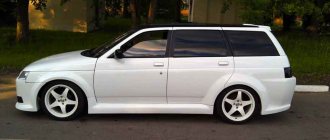
Many fans of the VAZ 2114 series want their car to be something different and stand out on the road. The best way to ensure this task is car tuning. It implies improved visual properties, driving characteristics and increased comfort. Most of the VAZ 2114 tuning is done by hand. The main parts subject to improvement include:
- car exterior (body, mirrors, glass);
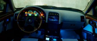
- car interior;
- engine compartment, chassis and other modifications that improve the driving performance of the car.
The listed parts of the car are processed in stages.
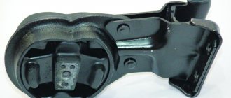
Steering rack modification
It's no secret that these cars have steering wheel vibration and unpleasant sounds on uneven road sections. You can say goodbye to this problem by installing a damper and power steering rack on the VAZ-2114. This revision has been discussed several times. You can find several options with drawings and detailed instructions. After installing the damper and power steering rack, noise and vibration of the steering wheel no longer bothered its owners.
Content
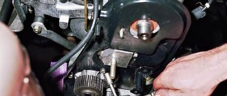
The car engine is the main power unit, on the characteristics of which much depends. Every year, the design of internal combustion engines becomes more complex and more efficient. However, this point does not apply to domestically produced cars - the installed engines are improved only in appearance, in general the design remains unchanged for many years. In order to significantly improve the driving performance of the car, the power unit should be modernized.
Sidebar: Important: With the right approach, you can significantly increase power or reduce fuel consumption, make engine operation more reliable, and make the sound more attractive.
Let's look at all the features of how to tune a VAZ 2114 engine: methods, possible improvements, problems with modernization and much more.
Modification of the rear lights of the VAZ-2114
There are many options for modifying taillights. Here are a few of the most popular:
- individual LED elements;
- LED rings;
- LED inserts and overlays.
For individual elements of LEDs, LED strips or rings are used; for the body, reflectors of different sizes and corresponding colors are excellent, which can be purchased without much difficulty in automobile stores. The paint is also selected according to your taste and desire. In order to place the rings in separate cylinders, you can use tin cans, after carefully cutting out the desired size. If you decide to mount LED trims inside the headlights, then do not forget that they are mounted on top of the rear optics.
In any of the listed options, you cannot do without soldering iron skills. If you don’t have the skills, but want to modify the taillights, then it’s better to contact a tuning studio, where professionals will do all the work for you.
Chip tuning
The manipulation in question is the basis for the functional transformation of the engine, after which the dynamics and power characteristics are improved, hidden resources are revealed without purchasing additional expensive parts. It is also possible to eliminate errors of the old version and signs of unstable operation. It is possible to increase power by 8-10%. An increase of up to 30% seems possible through the use of a turbocharger.
Before performing any manipulations, make sure that the motor is fully operational and adjusted.
Pinout of the dashboard of VAZ2113, 2114, 2115
There are 26 contacts on the VAZ-2114 instrument panel, each of which is responsible for the operation of the indicators of this panel. If a plus is supplied to the panel, then each contact displays information about the state in which the car is currently located.
White block (X1)
Red block (X2)
- Housing (weight) - black
- To ambient temperature sensor - cyan-magenta
- Tachometer (low voltage input from ECU) - brown/purple
- Fuse F16 (to terminal 15 of the ignition switch) - orange
- Tachometer (high voltage input from coil) - yellow
- Housing (weight) - black
- To fuse F3 of the mounting block (+battery) - white-purple
- Instrument lighting control - white
- Coolant temperature sensor. - green-white
- Turn signal RIGHT - blue
- To fuse F10 of the mounting block - brown
- Turn signal LEFT - blue-black
- Brake fluid level - pink-blue
- Check Engine Light to ECU Controller - White-Purple
- To the trip computer - brown
- To the ECU controller - pink and black
- Speed sensor - gray and yellow
- To the fuel gauge sensor - orange
- To the fuel gauge sensor - pink
- To the parking brake switch - brown-blue
- Fuse F14 of the mounting block - green-black
- Alternator terminal "D" through fuse panel - brown and white
- Hazard switch
- Oil pressure sensor - blue
- To terminal “50” of the ignition switch - purple
In addition, special indicators and signal sensors are installed on the instrument panel, and the panel itself is controlled by a special electronic unit. Having disassembled the instrument panel, you can see that there are two pads inside it: red and white. And all inputs, outputs and fuses are connected to the plug. If the sensors fail, they will need to be replaced. It is also better to replace damaged or oxidized wires. Indicator lights, like any other, sometimes burn out. Undoubtedly, they need to be replaced with whole ones. Along with them, the lamp sensor often burns out.
VAZ 2114 instrument panel connection diagram
- rear window heating switch;
- rear fog lamp switch;
- switch for headlights and direction indicators;
- mounting block;
- wiper switch;
- fog light switch;
- on-board control system display unit;
- instrument panel harness block to additional harness;
- instrument cluster;
- instrument panel harness connector to the on-board computer harness;
- instrument panel harness connector to the ignition system harness;
- instrument panel harness connector to the side door harness;
- fuse 16 A;
- fuse 16 A;
- ignition switch;
- lighting switch;
- heater electric motor;
- additional resistance of the heater electric motor;
- ignition switch unloading relay;
- rear fog light relay;
- starter relay;
- socket for connecting a portable lamp;
- cigarette lighter;
- instrument panel harness connector to the glove compartment lamp wiring harness;
- illuminator;
- illuminator;
- illuminator;
- heater switch;
- instrument lighting regulator with rheostat;
- brake light switch;
- horn switch;
- hazard switch;
- heater control lamp;
- fuse 16 A;
- seat heating relay;
Another variant of the connector pinout diagram
- checking the brake fluid level indicator. If you apply +, the brake light will light up. You can connect it to the red wire of the ignition switch, then, just like on 2110/2114, the lamp will be checked when the starter is turned on.
- Hazard warning lamp will light up when + is applied.
- high beam lamp, connect to the green-black wire.
- fuel level indicator, connect to the pink-red wire.
- to the speed sensor.
- speed signal output to the on-board computer. If there is one, then take the speed signal from this contact.
- Brake fluid level indicator, connect to the pink-blue wire near the lamp above the cigarette lighter. In the VAZ-2107, the lamp works the other way around: the sensor connects the lamp to ground and it lights up. You will have to either leave the lamp where it is, or in the new device, solder the lamp to + and swap the diodes (in this case, to check the lamp, pin 1 must be connected to ground, for example, to the parking brake lamp), or remove the black wire from the sensor on the tank, and connect instead the orange one from the EPHH unit, or the blue one from the ignition coil, while the diode in the wiring (between the beard and the glove compartment) must be disconnected; if this is not done, there will be a short circuit.
- left turn lamp, connect to the blue-black wire of the steering column switch block.
- Right turn lamp, connect to the blue wire of the steering column switch pad.
- instrument lighting, connect to the white wire.
- ground, connect to the black wire.
- power supply of devices, connect to the orange wire.
- if the device is simple (without microcircuits, etc.), then connect it to the blue-red wire (fuel reserve lamp), if there is a display under the tachometer, then connect it to the temperature sensor (take from a VAZ-2114, one contact to the device, the other to ground, place it either in the passenger compartment or in the engine compartment, but far from the engine and so that the wind does not blow).
- ground, connect to the white-black wire.
- low-voltage tachometer input (from the ECM), connect to the brown-blue wire.
- high-voltage tachometer input (from the coil), connect to the brown-blue wire.
- If there is a display under the speedometer, then connect it to the red and white wire at the brake light switch.
- coolant temperature gauge, connect to the green-white wire.
- outdoor lighting lamp, connect to the yellow wire.
- carburetor choke cover lamp, connect to the gray-orange wire.
- go to the ECM lamp. If the machine is injection, then connect one of the contacts to the orange wire, and the other to the remaining one.
- go to the ECM lamp. If the machine is injection, then connect one of the contacts to the orange wire, and the other to the remaining one.
- power supply of devices, connect to the orange-blue wire.
- handbrake lamp, connect to the brown wire.
- battery charge lamp, connect to the brown-white wire.
- low oil pressure lamp, connect to the gray-blue wire.
Release
As a rule, in this case, tuning is limited to installing a direct-flow muffler. There is a myth that such a measure can significantly increase engine performance, but this is not the case. Strictly speaking, there is an increase in power. However, it is so insignificant that it is extremely difficult to feel.
In addition, one muffler is not enough. High-quality work implies installation of the entire kit. This is a resonator with adjustable brackets (from 1,500 to 3,500 rubles), a tuned collector for 3,500 rubles. and, in fact, a muffler with an aluminum nozzle (round or oval) for 4,500 - 5,000 rubles.
Chassis
It is necessary to understand that modifications to the suspension should not contradict traffic regulations.
But this does not stop enthusiasts who upgrade the brake system by installing different calipers, pads and brake discs.
There are also frequent cases of underestimation, and this is usually not done by purchasing special springs or installing air suspension. As a rule, owners simply saw off one or more coils from the springs. Naturally, everything is done approximately, and this significantly impairs controllability.
Remote trunk control
The presence of an electric drive for the luggage compartment will significantly increase the ease of use of the vehicle. Often the need to open the trunk occurs while the engine is running. For example, the driver can put things in the trunk while the engine is warming up. There are three technological options for implementing the task under consideration:
- Introduction of trunk from tens. An electric door lock drive must also be present.
- A suitable electric drive kit can be installed in the luggage compartment lid.
- The electric drive can be connected to the factory door lock.
Considering the method you choose, do not forget to consider the use of lock control buttons and alarm keys. As a result of the work done, the time savings will be amazing.
Tapping into wires
Next to the driver's door, there are two wire harnesses running right along the floor. One of them has a cable coming from the parking brake and two wires to the turn signals. The second harness contains the door switch cable. This is where you need to start connecting. To do this, remove the sill trim along with the side panel. They are attached using self-tapping screws that must be unscrewed. Having done this, you can see the wiring harness shown in the photo:
This harness goes to the dashboard. We are interested in the door switch cable. If a 1N5401 diode is inserted into the wire break, the current should flow towards the limit switches. And the second diode 1N4001 is connected as shown in the figure.
The following figure shows the second harness:
At the same time, taps are made from the blue cables and the cords are pulled to the place where the alarm will be installed. And the handbrake wire is cut, and a 1N4001 diode is soldered into the cut with the cathode towards the switch.
ABS plastic
Body kits made from this plastic are made using thermal pressing technology in molds. Here you already need certain equipment, so the price of such elements is higher. Granular plastic is fed into a unit that heats it, resulting in a homogeneous mass that is fed into the mold under pressure.
Advantages of stamped body kits:
- low prices compared to carbon and polyurethane;
- sufficient strength;
- the surface has good adhesion to paints and varnishes.
Among the disadvantages is fragility at low temperatures, and if the technology is violated and there is an error in the geometry, the part simply cannot be installed.
Fiberglass
Let's briefly consider the features of different materials for body kits with their pros and cons. One of the oldest materials for making body kits is fiberglass. The molding technology is not too complicated, but the process is long and labor-intensive, so the price of such elements will be higher. The material is obtained by impregnating fiberglass fabric with epoxy polymer resin. To obtain the desired product, a mold is made from gypsum or other material and fiberglass and polymer resin are applied in layers. After hardening, the part is processed, sanded and painted in the desired color.
This method has certain features:
- inexpensive materials;
- sufficient strength;
- maintainability;
- light weight.
At the same time, quality strongly depends on compliance with manufacturing technology.
Connecting the central lock
First you need to study in detail the connection diagram for the central locking on a VAZ car - 2115,2114. Finding it is not a problem by searching on the Internet.
The central locking control module is located on the left under the dashboard. Looking there, you will find six wires coming out of the module housing. To install the alarm, you must disconnect the blue and brown cords. As a result, we get a connection corresponding to the following diagram:
Before connecting the alarm, you should make sure that it is not a toggle switch installed on the driver's door, but a standard actuator with five outputs. Otherwise, you will need to install an actuator, which is quite problematic.
On VAZ -2115,2114 cars, the white wire, which is connected to the seventh terminal, is usually responsible for unlocking. If there are no connections at terminals 7 and 5, then the eighth terminal is connected to the brown cord. It is this cord that is responsible for unlocking in this case.
Terminals number five and six are responsible for locking the lock. This arrangement of contacts is typical for almost all blocks of the “ninth” series.
For some reason, none of the instructions for alarms ever indicate that installation requires the purchase of additional elements.
We will definitely need:
- Two to three 1N4001 diodes per Ampere
- One 1N5401 3 Ampere diode
- Two 4 or 5 Ampere diodes if there are no separate outputs for turn signals.
When installing a Starline alarm system, the task is greatly simplified, since significantly fewer additional parts are needed.