02/04/2022 5,690 VAZ 2105
Author: Ivan Baranov
The VAZ 2105 generator provides power to all consumers included in the vehicle’s electrical network, and also charges the battery during operation of the power unit. The article provides a description of the device, typical problems, ways to fix them, and also includes step-by-step instructions on how to remove and connect the unit.
[Hide]
Connection diagram for generator in VAZ cars
The generator in cars is designed to generate electricity and charge the battery. If the normal operation of a car electric generator is disrupted, the battery begins to discharge and soon the car will stop starting completely - there is not enough battery charge. This device consists of a three-phase diode bridge, which, in turn, has 6 silicon diodes. Electrical voltage is created by the excitation of the rectifier at the moment when the rotor poles change under the stator windings. When the rotor rotates inside the machine stator, the poles of the rotor change. To increase the value of magnetic fluxes, the stator contains an electromagnetic exciting winding in the area of the magnetic cores. Marking and designation of wires:
- P - pink.
- F - purple.
- O - orange.
- B&W - black and white.
- KB - brown and white.
- CHG - black and blue.
- K - brown.
- H - black.
- B - white.
Connection diagram for the VAZ-2101 generator
Structurally, generator 2101 consists of the following main elements:
- The rotor is a moving part that rotates from the engine crankshaft. Has an excitation winding.
- The stator is the stationary part of the generator and also has a winding.
- Front and rear covers , inside of which bearings are installed. They have eyelets for attaching to the internal combustion engine. The back cover contains a capacitor necessary to cut off the alternating current component.
- Semiconductor bridge - called a “horseshoe” for its similarity. Three pairs of semiconductor power diodes are mounted on a horseshoe-shaped base.
- A pulley on which the VAZ-2101 generator belt is placed. The belt is V-shaped (on modern cars a multi-ribbed belt is used).
- The voltage regulator is installed in the engine compartment, away from the generator. But still it must be considered part of the structure.
- The brushes are mounted inside the generator and transmit the supply voltage to the field winding (on the rotor).
Generator - performance check
Many car enthusiasts are interested in how to test a new generator that has just been installed on a car? Or how to check that the old one has already failed, although it seems to be working normally? After all, driving with a faulty generator can have a number of unpleasant consequences, the easiest of which is completely discharging the battery and stopping the car, and the most severe is damage to the on-board network and devices.
In order to test this device, you will need a tester (multimeter).
The diagnosis itself is performed in the following order:
- Turn on the ignition.
- Check to see if the generator/battery lights on the instrument panel come on.
- Start the engine - if the light goes out, then everything is in order, if not, then there is a malfunction.
- Wait until the engine warms up to operating temperature.
- Turn on ALL electrical consumers - lights, fans...
- We bring the engine speed to 3500.
- Turn on the multimeter in voltage measurement mode and connect the probes to the battery.
- If the generator is working, the multimeter will show 13 volts, if less, then there is a malfunction.
- Without turning off the engine and maintaining speed, turn off all electricity consumers - the multimeter should now show 14.7 volts or slightly higher - this also indicates that the device is working properly.
By performing the test according to the specified scheme, you can quickly and accurately determine whether the generator is working. But, there are a number of indirect signs that may also indicate a malfunction of this device.
These include:
- the battery charging icon is constantly lit;
- interruptions in the operation of electrical equipment, flickering headlights;
- boiling of the electrolytic solution in the battery;
- Generator operation is too noisy (as a result of bearing failure).
If you detect even one of these signs, you should immediately perform a full check (according to the scheme described above). If it turns out that the generator is faulty, a new one should be installed instead. But we’ll look at which generator is better to put on a VAZ 2114 below.
Sources
- https://FokSevmash.ru/rashodniki-i-zapchasti/moshchnost-generatora-vaz-2.html
- https://RetroTruck.ru/rashodniki-i-zapchasti/moshchnost-generatora-vaz-2.html
- https://dmsht.ru/otlichiya-generatorov-dlya-vazov/
- https://kalina-2.ru/otechestvennie-avto/kakoj-stoit-generator-na-vaz-2107-karbjurator
- https://SpecTorg.su/obzory/generator-135-amper-na-vaz-2107.html
- https://RosAvto-SPB.ru/drugoe/generator-vaz-2110-pramo.html
- https://granta-service.ru/diagnostika/kakoj-generator-luchshe-postavit-na-vaz-2110-mnenie-spetsialistov.html
[collapse]
Connection diagram for the VAZ-2107 generator
1 - battery; 2 - negative diode; 3 - additional diode; 4 - generator; 5 - positive diode; 6 - stator winding; 7 - voltage regulator; 8 — rotor winding; 9 — capacitor for suppressing radio interference; 10 — mounting block; 11 — battery charge indicator lamp in the instrument cluster; 12 - voltmeter; 13 — ignition relay; 14 - ignition switch.
Connection diagram for the VAZ-2108 generator
The VAZ-2108 generator has a rather massive stator winding, since it uses a large cross-section wire. It is with its help that electricity is generated. The wire is wound evenly over the entire inner surface of the stator into recesses specially provided for this purpose in the magnetic core. It’s worth talking about the latter separately. The middle part, the generator stator, consists of a series of thin metal plates pressed tightly together. They are often boiled on the outside to prevent separation.
Connection diagram for the VAZ-2109 generator
- Alternator. The 37.3701 or 94.3701 series can be installed.
- Negative diode.
- Additional diode.
- Positive diode.
- Alternator warning lamp, also known as battery discharge lamp.
- Instrument cluster.
- Voltmeter.
- Relay and fuse box located in the engine compartment in the compartment between the engine and the vehicle interior.
- Additional resistors built into the fuse mounting block.
- Ignition relay.
- Egnition lock.
- Accumulator battery.
- Capacitor.
- Rotor winding.
- The voltage relay is located in the engine compartment.
Second version of the scheme
- block headlights
- side turn signal repeater
- battery
- lamp relay for monitoring battery charging
- electropneumatic valve
- carburetor microswitch
- generator
- headlight glass cleaner
- sound signal
- starter
- engine TDC indicator lamp
- engine compartment lamp
- oil pressure warning light sensor
- coolant temperature gauge sensor
- fluid level sensor in the hydraulic brake reservoir
- candles
- windshield washer pump motor
- distributor cap
- distributor
- ignition coil
- electric motor of the pump serving the headlight washers
- electronic control unit
- diagnostic block (installed on some cars)
- windshield wiper relay
- relay-interrupter for direction indicators and hazard warning lights
- wiper motor
- brake light switch
- electric motor of the heater (stove)
- additional resistance
- portable lamp socket
- reverse light switch
- Handbrake warning lamp switch
- relay and fuse box
- low beam headlight relay
- headlight high beam relay
- horn relay
- Relay for windshield wipers and headlight washers
- rear window defroster relay
- glove compartment lamp
- cigarette lighter
- dome light switches
- interior lamp
- rear window defroster switch
- hazard warning switch with warning lamp
- warning lamp block
- rear fog light warning lamp
- hand brake warning lamp
- warning lamp indicating a drop in brake fluid level
- windshield wiper and washer lever
- handbrake warning lamp relay
- horn switch
- outdoor light switch
- turn signal switch
- headlight switch lever
- egnition lock
- instrument light switch
- rear fog light switch
- instrument cluster
- warning lamp indicating insufficient oil pressure
- fuel reserve warning lamp
- fuel level indicator
- battery charging warning light
- water temperature indicator
- instrument lighting lamps
- voltmeter
- speedometer
- indicator lamp for turning on external lighting
- turn signal indicator lamp
- high beam warning lamp
- three-position heater fan switch
- rear window defroster
- fuel level and reserve indicator sensor
- rear light block
- license plate lights VAZ 2105
How to check the generator yourself
How to check a VAZ generator using the example of model 2109. Generator type 94.3701 alternating current, three-phase, with a built-in rectifier unit and an electronic voltage regulator, right-hand rotation.
Generator connection diagram . The voltage to excite the generator when the ignition is turned on is supplied to terminal “D+” of the regulator (terminal “D” of the generator) through indicator lamp 4 located in the instrument cluster. After starting the engine, the excitation winding is powered by three additional diodes installed on the generator rectifier block. The operation of the generator is controlled by a warning lamp in the instrument cluster. When the ignition is turned on, the lamp should be on, and after starting the engine, it should go out if the generator is working. If the lamp is brightly lit or glows half-lit, it indicates a malfunction.
The “minus” of the battery should always be connected to ground, and the “plus” should always be connected to the “B+” terminal of the generator. Failure to turn the battery back on will immediately cause increased current through the generator valves and damage them.
It is not allowed to operate the generator with the battery disconnected. This will cause short-term overvoltages to occur at the “B+” terminal of the generator, which can damage the generator voltage regulator and electronic devices in the vehicle’s on-board network.
It is prohibited to check the functionality of the generator “for spark” even by briefly connecting the “B+” terminal of the generator to ground. In this case, significant current flows through the valves and they are damaged.
Criteria for choosing car generators
- Maximum power. Power is one of the main characteristics of VAZ generators. It must ensure an uninterrupted supply of current and supply electricity to the battery, which is discharged due to the operation of regular electricity consumers at low speeds of the power unit. To perform basic tasks, the device must have the required power. The required indicator is indicated in the vehicle operating instructions.
- Current strength. The factory generator installed in the car is not designed for a large number of additional consumers, but at the same time it has a certain reserve. If the autogenerator is “not enough,” then before purchasing a new device, first inspect the old equipment, clean the contacts, check the bearings, etc. You shouldn't use 120A generators in every car. First of all, it's expensive. Secondly, the current may be excessive. Such power-generating devices are installed in tuned cars with a powerful acoustic system.
- Dimensions. Before purchasing, it is also worth comparing generators by overall dimensions. The device must be compact with high technical characteristics.
- Noise level. The generator should not make too much noise during operation. This “disease” often affects high-power generators that are sold at a low price. One of the main reasons for the appearance of extraneous sounds (hum) is the poor quality of bearings, which wear out quickly.
- Availability of guarantee. If there is a warranty, you can exchange a faulty device for a new one if it is defective.
Replacement and removal of the electric generator
The generator on a VAZ car is removed either for complete replacement in case of failure or to carry out repair work to replace faulty parts. To perform dismantling, prepare a standard set of tools; it is advisable to drive the car into the inspection hole.
- Disconnect the battery.
- Remove the protective rubber cap from terminal “30” and unscrew the nut and remove it from the wire stud.
- Disconnect the block with wires from the generator connector.
- We loosen the tightening of the generator to the adjusting bar, then lift it all the way up to the cylinder block and remove the belt from the pulleys.
- Completely unscrew the bolt securing the adjusting bar to the cylinder block, then from the bottom of the car unscrew the 2 bolts securing the lower bracket to the block and remove the generator, pulling it out of the engine compartment.
Source
Technical specifications
If the old generator fails, many motorists wonder which generator they should now replace the old one with.
There is no need to invent anything here. The most correct solution is to install the same generator as before, or a more powerful one.
Today, the VAZ 2110 provides for the use of three types of power supply devices:
- Katek 5102.3771. The generator produces 80 Ampere power and its voltage is approximately 14V.
- Katek 94.3701. This is a device with the same parameters. They are not seriously different.
- Catek 120 amp. A generator that is more adapted to modern realities, when in addition to standard electrical equipment, motorists install many additional devices.
If you have a powerful audio system in your car, you use an electric pump powered by the car, as well as a number of other additional consumers, it is recommended to install a 120-amp unit instead of a standard 80-amp generator.
If we take into account the size of the devices, then we can distinguish between ordinary and compact ones. They have a certain difference in design
To be specific, the differences are in the following components:
- Brackets;
- Anchor;
- Excitation wire;
- Drive pulley;
- Number of mounting bolts.
But in reality this does not play a special role. After all, the structure of all generators used for the VAZ 2110 is the same. Therefore, let's look at the circuit and structure of this unit.
| Element | Functions |
| He's an anchor. It is a rotating element of the generator, which creates a magnetic field due to the excitation winding located on the shaft. The field wire receives power from the slip rings. They are mounted on the same shaft. There was also room for a drive pulley, field winding wire, bearing assembly and fan impeller. There may be 1-2 last ones | |
| This is a stationary three-phase element that includes three windings. They provide the creation of alternating current. The windings are connected to each other using a triangle or star | |
| A lightweight non-magnetic aluminum alloy is most often used to make the generator housing. The body looks like a pair of covers connected by a bolt. The front cover is located near the drive pulley, and the rear cover is located on the side of the slip rings. Each connecting bolt must be tightened. To disassemble the housing, simply unscrew the mounting bolts. | |
| The upper mounting bracket for the generator uses two bolts, while the lower bracket is predominantly mounted on one bolt. In some cases there are two. It is not recommended to modify the brackets, since the factory one performs important functions. The purpose of the brackets is to hold the generator. It is recommended to monitor the condition of the brackets as they are subject to wear and breakage | |
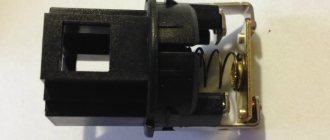
| Brush unit | It consists of a pair of graphite brushes, springs that press the brushes, as well as a brush holder |
| Brush holder assembly and voltage wires | This design is typical for modern Katek generators. Therefore, if the regulator fails, you will have to replace the entire assembly |
| Rectifier block | Equipped with 6 diodes, it is responsible for converting alternating current into direct current. It is direct current that is required for the operation of all auto equipment. This element charges the battery, among other functions. |
| Belt drive transmission | The belt drive allows you to increase the speed at which the crankshaft rotates. If the pulley has a small diameter, then the V-belt will wear out faster. Therefore, for small driven pulleys it is recommended to use a poly-V-ribbed drive. It is most often found in modern generators |
The presented device is relevant for all generators used on the VAZ 2110, regardless of their power - 80-120 Amperes.
Margin of safety
If we take into account the standard Katek generator, which is installed on domestic dozens, then its resource is enough for about 10 years of operation or 140 thousand kilometers. The specified safety margin of the device can only be relied upon if it is handled properly
The specified safety margin of the device can only be relied upon if it is handled properly.
Many people fear that a powerful 120 A generator can negatively affect the condition of the battery. In practice, nothing like this happens. Moreover, installing a more powerful unit is recommended if you plan to install an impressive audio system or video equipment on the car.
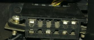
Connection diagram and repair of the VAZ 2105 generator
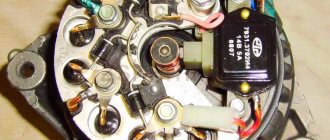
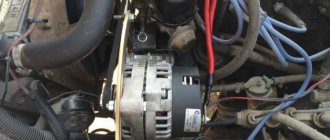
This is the unit we are talking about
To provide electrical energy to the electrical appliances of the VAZ 2105 car, as well as to recharge its battery while the engine is running, there is a generator in the car. Until 1987, the VAZ 2105 was equipped with units of the G 222 model, and later with the 37.3701 model. In both cases, the generator is a three-phase electrodynamic device in which the sinusoidal voltage of each phase is rectified using a built-in rectifier. This part is a three-phase diode bridge of a VAZ generator, consisting of six silicon diodes. The voltage is produced by exciting the rectifier by the three stator windings when the rotor poles change underneath them. The rotor poles change polarity as it rotates inside the stator, and to increase the value of magnetic fluxes, it has an electromagnetic excitation winding inside the magnetic cores. The rotor rotates through a belt drive from the front pulley of the engine crankshaft (injector) together with the pulley of the cooling system pump.
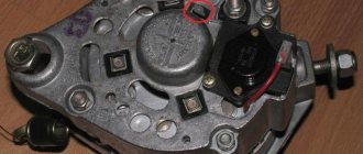
Features of the generator device
The generator housing consists of two covers made of aluminum alloy, tightened with four bolts and nuts, between which a round stator core is clamped. Rotor bearings are installed in the covers: the front one is in a through bearing, the rear one is in a blind seat of the cover. The rotor rotates inside the stator and housing on two bearings. The front end has a slot for a key and a thread for the fan nut. An adjusting washer is installed between the front rotor and the front bearing, which is often forgotten to be installed when repairing the generator. At the rear end of the rotor shaft, in front of the rear bearing, two copper slip rings are pressed in, insulated from the shaft and connected to the ends of the field winding.
A BPV6-50 rectifier is installed to the inside of the back cover. It consists of two horseshoe-shaped aluminum buses insulated from each other, into which three silicon diodes (valves) of the BA-20 type are pressed. The internal bus is isolated from the housing, but is connected to the generator terminal bolt “30”, while the other has contact with ground. The legs of the diodes in pairs from each bus are bolted to the ends of the phase windings of the stator, and their other ends are connected together - a star connection. In the G 222 generator, a wire goes from this point to a terminal on the back cover, from which a wire goes to terminal “85” of the RS-702 type charge indicator relay. There are no wires at 37.3701 from the common point of the phase windings.
Brushes are pressed to the contact rings of the rotor by springs, one of which is connected to terminal “B”, and the second to terminal W of the voltage regulator installed on the brush assembly in the upper rear part of the generator. In 37.3701 there are three diodes connected at one end to the phase windings, and the second are connected to one point, the wire from which goes to the regulator relay terminal Sh and terminal “61” on the rear surface of the generator. The diodes are connected in such a way that they pass positive half-cycles to pin “61”.
The electronic voltage regulator is non-separable and since 1996 has been installed in a metal case riveted to the brush holder. A capacitor is mounted between the housing and terminal “30”.
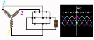
Generator connection diagram
To control the battery charge level in a VAZ 2105 car, it is necessary to monitor the output rectified voltage, which is maintained within 13, June 14.2 V. The regulator relay compares the voltage in the vehicle's on-board network with the reference one and, if this level is exceeded, reduces the voltage on the exciting winding , increasing the resistance between one of the rotor brushes and the “ground”. When the voltage in the vehicle network decreases, the regulator lowers the resistance, increasing the current in the field winding and, accordingly, the voltage at terminal “30”. Such cyclic processes occur at a frequency of 50-250 times per second.
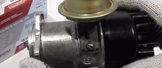
Basic malfunctions and ways to eliminate them
You can check the VAZ 2105 generator injector for serviceability on the car without removing it from the engine. Problems can be identified using diagnostics, using the diagram, and then eliminated (author of the video - Autoelectrics HF).
| Malfunction | Remedy |
| The motor is running, but the voltmeter needle does not leave the red zone | |
| Broken or poor belt tension. | Adjust the tension or replace the belt. |
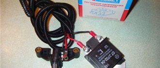
| The voltage regulator is faulty. | Replace with new one. |
| Sticking, wear of brushes. | Replacing the brush assembly, eliminating sticking. |
| Disturbances in the supply circuit of the excitation winding. | Chain restoration. |
| Short circuit between turns, break in the stator winding. | Stator replacement. |
| The voltmeter needle is in the white zone, but the mains voltage is below 13.6V, the battery is not charging | |
| Insufficient belt tension. | Tighten the belt. |
| There are many consumers switched on that require large amounts of electricity. | Limit the number of consumers. |
| The battery terminals and wire tips at the terminals of the generator unit are oxidized or loose. | Clean from oxidation, tighten contacts. |
| The voltmeter pointer is moving towards the yellow zone, the battery is overcharging, the voltage in the network exceeds 14.7V | |
| The voltage regulator is broken. | Replacement. |
| Bad contacts. | Clean and tighten fasteners. |
| The ignition is turned on, the voltmeter needle does not move | |
| The fuse has blown. | Install a new element. |
| Violation of the integrity of the power supply circuit of the instrument panel. | Chain restoration. |
| Increased noise during operation of the generating set | |
| The bearings have become unusable. | Replace parts. |
| Short circuit between turns in the stator winding (howl). | Stator replacement. |
| The brushes squeak. | Clean the contact rings and brushes. |
| Weak pulley fastening. | Tighten the fastening nuts. |