This article will discuss the VAZ-2106 generator. Its connection diagram is below, but at the very beginning we will talk about the general design of this device. With its help, mechanical energy is converted into electricity. The main function of a car generator is to recharge the battery. It also helps provide power to all equipment located in the car, including the engine. On all machines, generators produce alternating current. Only after some transformations does it stabilize and become permanent.
General information
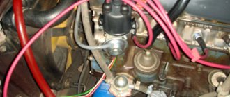
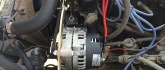
The generator is located directly next to the engine, usually in the front part. The drive is carried out from a pulley located on the crankshaft. On some vehicles, such as hybrid vehicles, the alternator can act as a starter. The designs of both mechanisms are very similar, so some manufacturers are trying to reduce the number of electric machines. Please note that the connection diagram for the VAZ-2106 generator is the same as for a similar mechanism in any other car.
All generators have certain differences, for example in the housing, rectifier assembly, drive pulleys, but the general elements are still almost identical in all of them. What remains unchanged is the housing with the bearings located in it, the movable rotor, which rotates inside the stationary stator. The alternating voltage is removed from the latter. No generator can do without a rectifier unit and a voltage regulator.
Electrical systems of VAZ 2106
The electrical circuit of the VAZ sixth model includes a number of systems that ensure the operation of consumers in different parts of the car. This:
- ignition system;
- control and lighting system;
- cigarette lighter operation system;
- engine starting system;
- carburetor solenoid valve control system;
- windshield wiper and washer system;
- heating system;
- sound signal system;
- component of the engine cooling system;
- system of indicators and status sensors.
The ignition system includes an alternating current generator, a rectifier unit, a current distribution system, spark plugs, fuses and a number of supporting elements. The system removes low voltage current from the generator brushes, converts it into high voltage current in transformers and, in accordance with the firing order of the engine cylinders, supplies it to the spark plug. The converted current must have enough energy to create electricity inside the engine cylinder and ignite the working mixture.
Control and lighting devices include all lighting devices, such as front and fog lights, interior lighting lamps, trunk lighting lamps, as well as additional lighting elements installed. This also includes turn signals, brake lights, side lights and others.
In general, these devices are an important part of ensuring compliance with traffic rules, and therefore are constantly powered either through the battery or through the generator and are turned off last. The same applies to the sound signal system, which provides clearer information to other road users about changes in the situation on the road.
The engine starting system includes a battery and a number of elements that supply high current to start all consumers and rotate the engine shaft to starting speed. When the crankshaft reaches this frequency, the alternating current generator comes into operation - now it powers all consumers and charges the battery.
For satisfactory operation of the fuel supply system at high speeds, the VAZ 2106 carburetor is equipped with a solenoid valve. It regulates the operation of the internal combustion engine at idle and operating speed. To control it and synchronize its operation with the operation of the engine, the electrical circuit has its own separate system. It is recommended to download the VAZ 2106 electrical diagram and familiarize yourself with its operation.
The engine cooling system fan control system ensures consistently normal thermal operating conditions for the internal combustion engine and increases the service life of the most expensive part of the vehicle. Indicators of the vehicle's operating status are connected to sensors installed in critical places on the VAZ 2106. The indicators take readings by converting physical quantities into an analog or digital signal, which is processed and sent to the indicators. From the latter, in turn, the necessary information can be read.
The VAZ 2106 has several electrical equipment systems designed to make life easier for the driver and increase driving comfort. These include windshield wipers, heater, defroster, cigarette lighter and others. Some of them are useful, others were created on the principle of “so it was.” Which one to use is up to the owner to decide, but the very fact that there is a choice is pleasing.
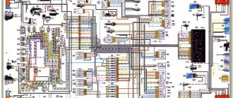
The electrical circuit of the VAZ 2106 car is very ramified and it is not possible to describe it all in one article. If there is a desire or there is a need to deepen and expand knowledge about the most popular car of the Union, it is strongly recommended that you familiarize yourself with special specialized literature or, at least, with a photo of the electrical circuit diagram.
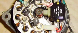
Generator rotor
Most generators are equipped with a brush mechanism. In many designs it is combined with a voltage regulator. The rotor creates a magnetic field that rotates thanks to the drive belt. The field winding, which is located on the rotor itself, is powered through a voltage regulator. On the back of the rotor there are rings through which the winding is powered. Without them, the VAZ-2106 generator connection circuit turns out to be inoperative.
In most designs, these rings are made of pure copper. But sometimes you can find them made of steel or brass. There is also an impeller on the rotor, which is used to blow air over the device body. The drive pulley is fixed next to the impeller. The front and rear covers of the generator contain maintenance-free ball bearings.
A little about the stator
An electric current is created in the stator. It has three windings of copper wire. This wire is wound on a special steel core. Typically, the generator has a total of 36 slots into which the windings fit. It can fit into the grooves in two ways - wave or loop. The windings are connected according to the “star” circuit. This is the most common circuit used in automobile alternators. It is worth noting that the connection diagram of the VAZ-2108 generator to the VAZ-2106 is practically no different. The only difference is that in the first model the voltage regulator is combined with the brush assembly.
All elements of the mechanism are housed in the housing. Actually, the body is just two aluminum covers, which are tightened with bolts. The choice of aluminum elements is quite reasonable, since it is not magnetized, it is very light in weight, and most importantly, it has a high degree of heat transfer. Using the brush assembly, current is transmitted to the rotor winding. Its design consists of a pair of brushes made of graphite, springs that allow them to be pressed more tightly to the rings on the rotor, as well as a brush holder. As noted earlier, in most modern cars the brush holder and voltage regulator are assembled in one unit.
Eliminating the causes of charging failure on the VAZ 2106
To check the electrical circuit of a car, you need a simple multimeter or voltmeter. The most common reasons for loss of charging voltage are:
- the generator belt tension is too weak or it is worn out;
- generator malfunction (brush wear, diode bridge malfunction, break or burnout of stator or armature coils);
- voltage regulator malfunction;
- break in the charging circuit.
The most common cause of charging failure is a faulty voltage relay. In order to check its functionality, it will be enough to remove both wires from it, connect them together, and start the engine. Provided that all other elements in the circuit are good, the voltage in the circuit will reach about 17 V or more. If the voltage does not increase, then it is necessary to check the presence of +12 V at the terminal connected to pin 15 of the relay regulator. If it is missing, check the fuse responsible for the circuit and the integrity of this circuit itself.
If there is power at this terminal, then you need to check the connections in the generator excitation circuit. Connect a test lamp between +12 V of the battery and the wire that is connected to terminal 67 of the voltage regulator relay. In this way, you can check the voltage relay-generator circuit, as well as the serviceability of the generator brushes and its armature windings. If there is no voltage at the lamp terminals, an assumption is made that the rectifier bridge is faulty.
Next, check the serviceability of the conductor from the generator to the relay regulator. To do this check, you need to disconnect the terminal from the generator and connect it to -12 V. The glow of the control lamp indicates faulty brushes or broken armature windings. If a generator malfunction is suspected, it is removed from the vehicle and completely disassembled. Next, the serviceability of each diode in the diode bridge of the generator is checked, and the stator and armature coils are tested for breakage or burnout. Faulty elements are repaired or replaced.
The VAZ 2106 battery charging circuit provides for a constant voltage of 13.5 to 14.3 V, regardless of engine speed. However, there are cases when, at medium engine speeds, the voltage noticeably “drops” when an additional load is turned on. If such a phenomenon occurs, it is necessary to check the tension of the generator belt and adjust it. Poor contact at the battery terminals sometimes also leads to this effect.
If the voltage at the battery terminals is higher than the specified limits, you need to check all contacts, starting from the positive terminal of the battery to the voltage regulator relay. If all contacts are normal, then the relay regulator must be replaced.
Timely care of the car’s electrical equipment, the condition of the battery contacts and terminals, and regular checking of the belt tension and electrolyte level in the battery will allow your car’s engine to operate for a long time and without problems, and you will avoid many malfunctions on the road.
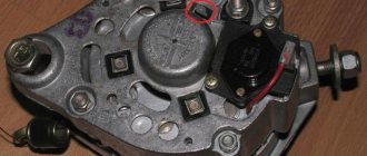
Rectifier unit
The rectifier unit is necessary in order to convert the alternating sinusoidal voltage generated by the generator into the constant voltage necessary to power the entire on-board network. It is essentially a horseshoe-shaped plate containing semiconductor diodes. There are six of them in total, therefore, there are two semiconductors in the circuit of each phase. The horseshoe plate on which the diodes are mounted also serves as a heat sink. With its help, heat is transferred to the body of the generator itself. In some generators, the field winding is connected through another circuit consisting of two semiconductors. It should also be mentioned that the connection diagram of the VAZ-2107 generator to the VAZ-2106 is similar, there are no differences.
The principle of operation of electrical equipment of the VAZ 2106
The ignition switch has 4 positions, when each of them is activated, certain connectors and contacts are switched:
- In position “0”, the battery current is transmitted only to connectors 30 and 30/1, the others are de-energized.
- In position “I”, current is supplied to connectors 30-INT and 30/1-15, while the “dimensions”, windshield wiper, and fan heating system of the heating complex are energized.
- In position “II”, contact 30-50 is additionally connected to the previously used connectors. In this case, the ignition system, starter, panel sensors, “dimensions” and “turn signals” are included in the circuit.
- In position “III” only the “dimensions”, horn and windshield and stern wipers are activated. In this case, the current is available only to connectors 30-INT and 30/1.
A number of cars of this brand are equipped with such devices as a rear window heating complex, an electric windshield washer, a light relay, etc. The power supply to these gadgets is supplied via a separate line through the ignition switch at the key positions “I” and “II”.
Important: because The washer tank is made of PVC material and is a dielectric, then the electric motor is additionally equipped with a negative wire and when working with it it is necessary to use dielectric protection on the connectors
In the “six”, the following power circuits operate continuously under current: horn, brake lights, emergency lights, cigarette lighter socket, “carrying” plug, instrument lighting. The leading circuits of the electrical equipment of vehicles are subject to protection by fuses, which are located in two special blocks (main and spare), located on the driver’s side under the dashboard.
One of the elements of the VAZ 2106 wiring diagram is a safety block, the design of which does not meet modern requirements for the maintenance of electronic equipment. Flaws:
- an unstable connection between the fuse and the socket leads to the appearance of burnt spots;
- during operation, the safety element is subject to heating, which negatively affects the nearby fastening sockets;
- the low cost of replaceable fuses does not guarantee their reliability, so checks of this unit should be carried out regularly.
Using the so-called "bugs" can lead to a vehicle fire, because there is a high probability of committing a short circuit. There is a completely safe option for upgrading standard products, in which blade fuses must be installed, the seats of which are perfectly integrated into the safety block.
Advantages of blade fuses:
- stable contact of the product with the mounting location;
- the fusible type element is sealed in a transparent PVC casing;
- dynamic heat dissipation due to the increased contact area.
Important: the “six” generator unit, the wiring to it, as well as to the battery, starter, bobbin, optics relay and some other elements are not equipped with safety elements
Additional rectifier
This rectifier is used to create an obstacle to the flow of current from the battery while the engine is not running. If the windings are connected according to a star circuit, it is necessary to mount two semiconductors on the common terminal, this will increase the total power of the entire installation by a maximum of 15 percent. The rectifier unit is connected to the generator system using mounting pads. The connection is made by bolts, welding, and less often by soldering. You can even say that the connection diagram for the VAZ-2106 starter and generator is very similar, only the functions of the nodes are different.
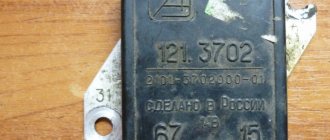
Voltage regulator
Using a voltage regulator, a certain value is maintained on the excitation winding. Today, most generators are equipped with an integrated relay-regulator. It is worth noting that there can be two designs of relay regulators: a hybrid one, in which radio-electronic components are used, such as zener diodes, resistors, capacitors, and an integral design, in which all the elements included in the relay regulator are made on one semiconductor wafer . This is the main element that makes up the VAZ-2106 generator. The semiconductor connection diagram is given in the article.
Understanding the reasons for charging problems on the VAZ 2106
To check the electrical circuit of a car, you need a simple multimeter or voltmeter. The most common reasons for low charging voltage are:
- The generator belt tension is too weak or too worn;
- generator malfunction (worn brushes, faulty diode bridge, broken or burnt stator or armature coils);
- voltage regulator malfunction;
- shaving in charging area.
The most common cause of charging failure is a malfunction of the voltage relay. In order to verify its usefulness, it will be enough to remove the grudge from the grudge, put it together, and start the engine. Because of the fact that all other elements of the lance are attached, the voltage in the lance is close to 17 or more. If the voltage does not increase, then it is necessary to check the presence of 12 V at the terminal connected to pin 15 of the relay regulator. If necessary, check the lance, which confirms the lance and the very integrity of this lance.
If the device is connected to this terminal, it is necessary to check the connection in the generator wake-up circuit. Connect the test lamp between the 12 V rechargeable battery and the dart, which connects to connection 67 of the voltage regulator relay. In this way, you can check the voltage relay-generator circuit, as well as check the generator brushes and armature windings. If there is no voltage at the lamp pins, worry about a malfunction of the direct bridge.
Next, check the serviceability of the conductor from the generator to the relay regulator. For such verification it is necessary to disconnect the terminal from the generator and connect it to -12 Art. The indicator light is on to indicate faulty brushes or broken armature windings. If a malfunction of the generator is suspected, it should be removed from the vehicle and examined further. Next, check the integrity of the diode in the diode bridge of the generator, check the continuity of the stator coils and armatures for damage or burnout. Faulty elements must be repaired or replaced.
The VAZ 2106 battery charging circuit shows a constant voltage of 13.5 to 14.3, regardless of engine speed. However, there are breakdowns when the voltage on the middle turns of the engine noticeably “sags” when the additional voltage is turned on. If such a phenomenon occurs, it is necessary to check the tension of the generator belt and adjust it. Weak contact at the battery terminals can also lead to this effect.
Since the voltage at the battery terminals is higher than the specified values, you need to check all contacts, starting from the positive terminal of the battery to the voltage regulator relay. If all contacts are normal, then the relay regulator prompts replacement.
Keeping an eye on your car's electrical system, the contacts and terminals of the battery, regularly checking the belt tension and the level of the electrolyte in the battery will allow your car's engine to run smoothly and without problems, and you will avoid a bug atoch malfunctions in dozі.
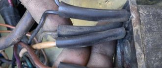
Drive belt
Of particular note is the drive belt. Please note that the generator rotor rotates faster than the crankshaft. Moreover, the difference can be 2-3 times. Depending on the car, a V-shaped or poly-V belt can be used. The first has the disadvantage of rapid wear. The second one is more universal, wear is much less, it works very well if the pulley diameter on the generator rotor is small. Consequently, with the help of a poly V-belt it is possible to rotate the generator rotor more quickly. Almost all modern cars are equipped with generator sets with a serpentine belt. But the VAZ-2106 generator, the connection diagram of which you now know, is driven by a V-belt.
A built-in or remote regulator is one of the main components of the generator, ensuring stable operation of the entire vehicle power supply system. In some cases, it is useful to install an external regulator if overcharging or other difficulties are observed. Learn how to properly connect remote-type relays.
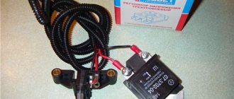
Remote controller
ATTENTION! A completely simple way to reduce fuel consumption has been found! Don't believe me? An auto mechanic with 15 years of experience also didn’t believe it until he tried it. And now he saves 35,000 rubles a year on gasoline! Read more"
This often happens to drivers. The brushes of the generating device burn out. The regulator is built in along with the brushes. We have to change everything together. And here’s some advice from experts: it’s better to install an external regulator than a built-in one. The models released recently have not been praised very much.
Okay, do you think I’ll install an external one, but how do I connect it? It turns out that there is a convenient scheme that makes it easy to carry out all this modernization.
Some important points:
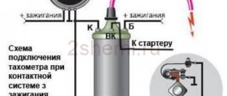
- do not confuse the chips on the regulator numbered 67 and 15 (the first should be connected to the generating device, and the second should go to the fuses);
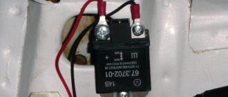
This is what the connection diagram looks like
In the lower photo we see a diagram that shows the connection of the already built-in regulator relay.
It is suitable for connecting to “fives”, “sevens”, VAZ 2104, if the PG is installed from a VAZ “kopek”. As you can see, the remote-type regulator relay is connected via two terminals. Pin 15 goes to the fuse.
The second pin 67 is connected to the generator. The wire is connected to the brush chip.
Also, the remote-type relay must be connected to ground - any part of the body.
A relay is nothing more than a switch that serves to close and disconnect individual zones of an electrical circuit that occur at specific electrical values. A machine relay is otherwise called a load voltage switch, and this is 100 percent true. When the power supply unit, fan or starter consumes more current than necessary, the relay trips.
The relay consists of an electric type magnet, an armature and a switch. In this case, the electromagnet is a cable twisted around an inductor with a magnetic rod, and the armature is a special plate that controls the contacts.
As soon as electrical voltage passes through the magnet winding, an electric field is created. A special pusher presses the armature against the core and, thereby, the contacts switch.
Attention. There are two types of relays used on VAZ cars. This is a non-contact relay-regulator and MER (electric). It is the diagram of the last relay that is shown in the picture below.
The non-contact relay or NERR is a fairly new unit that does not require any additional adjustments or regulation. As for the MED, this is an old-style device, the production of which has currently been suspended.
So, the BRN or built-in regulator is a device consisting of a microcircuit, a transistor and a housing with brushes. If the built-in regulator fails, it is replaced with a new one, or an external one is installed.
The external regulator is easy to install if you strictly follow the instructions.
Modernization involves dismantling and disassembling the generating device.
Replacement and removal of the electric generator
The generator on a VAZ car is removed either for complete replacement in case of failure or to carry out repair work to replace faulty parts. To perform dismantling, prepare a standard set of tools; it is advisable to drive the car into the inspection hole.
- Disconnect the battery.
- Remove the protective rubber cap from terminal “30” and unscrew the nut and remove it from the wire stud.
- Disconnect the block with wires from the generator connector.
- We loosen the tightening of the generator to the adjusting bar, then lift it all the way up to the cylinder block and remove the belt from the pulleys.
- Completely unscrew the bolt securing the adjusting bar to the cylinder block, then from the bottom of the car unscrew the 2 bolts securing the lower bracket to the block and remove the generator, pulling it out of the engine compartment.
Source