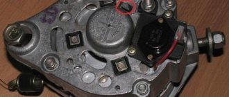
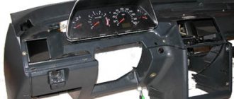
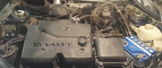
This is the unit we are talking about
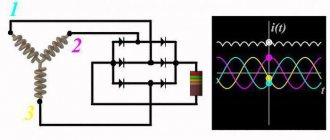
To provide electrical energy to the electrical appliances of the VAZ 2105 car, as well as to recharge its battery while the engine is running, there is a generator in the car. Until 1987, the VAZ 2105 was equipped with units of the G 222 model, and later with the 37.3701 model. In both cases, the generator is a three-phase electrodynamic device in which the sinusoidal voltage of each phase is rectified using a built-in rectifier. This part is a three-phase diode bridge of a VAZ generator, consisting of six silicon diodes. The voltage is produced by exciting the rectifier by the three stator windings when the rotor poles change underneath them. The rotor poles change polarity as it rotates inside the stator, and to increase the value of magnetic fluxes, it has an electromagnetic excitation winding inside the magnetic cores. The rotor rotates through a belt drive from the front pulley of the engine crankshaft (injector) together with the pulley of the cooling system pump.
The electrical circuit of the VAZ 21053 car differs from the instrument circuit of the 2105 model in that it contains an electronic engine control system (ECM) and various additional sensors. Therefore, on the VAZ 21053 the power supply system has a different terminal shape than on the 2105. The ignition switch of the first model, when the starter is turned on, turns off secondary circuits and devices.
In general, the VAZ 21053 and 2105 generators are identical. But how to connect a generator to a VAZ 21053, because in this model the injector needs more current produced? How to connect a generator from the “ten” to 80 A? The mounting and connection diagram of the VAZ 21053 are the same as it, so there will not be any special problems here.
Connection diagram for generator in VAZ cars
The generator in cars is designed to generate electricity and charge the battery. If the normal operation of a car electric generator is disrupted, the battery begins to discharge and soon the car will stop starting completely - there is not enough battery charge. This device consists of a three-phase diode bridge, which, in turn, has 6 silicon diodes. Electrical voltage is created by the excitation of the rectifier at the moment when the rotor poles change under the stator windings. When the rotor rotates inside the machine stator, the poles of the rotor change. To increase the value of magnetic fluxes, the stator contains an electromagnetic exciting winding in the area of the magnetic cores. Marking and designation of wires:
- P - pink.
- F - purple.
- O - orange.
- B&W - black and white.
- KB - brown and white.
- CHG - black and blue.
- K - brown.
- H - black.
- B - white.
Noise during operation
If there is a characteristic noise in the generator area, this may be wear on the armature bearings. The front element suffers most often, since the greatest loads are placed on it. After disassembling the generator, it is necessary to carefully inspect the condition of the holes for the bearings. If the wear in it is greater than the gap between the stator and the armature, the front cover of the generator must be replaced.
Otherwise, the armature will touch the stator pole during operation. The bearing is selected not only by its internal and external diameters, but also by its width. For example, if it is a Bosch generator, a bearing from the support of the input shaft of the GAZ-24-10 gearbox can be installed in the front part of the armature. In the rear part of the “Classic”, elements from “Tavria” and “Moskvich” are used. It is worth noting that on the VAZ-2105 voltage generator the winding is powered through the instrument panel indicator lamp. Therefore, if the circuit breaks, if the device has stopped producing current, you need to “conduct” a path from the winding to this light bulb. It is recommended to use a multimeter.
Connection diagram for the VAZ-2101 generator
Structurally, generator 2101 consists of the following main elements:
- The rotor is a moving part that rotates from the engine crankshaft. Has an excitation winding.
- The stator is the stationary part of the generator and also has a winding.
- Front and rear covers , inside of which bearings are installed. They have eyelets for attaching to the internal combustion engine. The back cover contains a capacitor necessary to cut off the alternating current component.
- Semiconductor bridge - called a “horseshoe” for its similarity. Three pairs of semiconductor power diodes are mounted on a horseshoe-shaped base.
- A pulley on which the VAZ-2101 generator belt is placed. The belt is V-shaped (on modern cars a multi-ribbed belt is used).
- The voltage regulator is installed in the engine compartment, away from the generator. But still it must be considered part of the structure.
- The brushes are mounted inside the generator and transmit the supply voltage to the field winding (on the rotor).
What to do if the generator does not work
If the generator does not work, then the red battery discharge light continues to light when the engine is running.
Check the alternator belt.
Check the 10th fuse, clean its contact points.
Check the voltage at the end of the wire that goes to point 15 of the voltage regulator, it should be 12 Volts when the ignition is on.
Connect the wires included in the voltage regulator 15 and 67, connect a voltmeter to the battery, start the engine, the voltage should increase to 16 Volts, this means that the generator is working, but the voltage regulator is broken and needs to be replaced.
If the voltage remains 12 Volts, then check the wire from point 67 of the voltage regulator to the generator brushes; the wire may jump out of the generator brush assembly, or there is poor contact in this place. Correct the wire, if the generator does not work, check the tightness of the power terminals at the generator output; if everything is tight, then the generator is faulty and must be removed.
If the generator is very old, it must be replaced.
If the battery is discharged and the light does not light, then you need to check the voltage with a voltmeter. If the voltage on the battery is above 13.5 Volts, then the generator is working, but the battery is no longer suitable.
If the voltage is less than 13.5 Volts and the light bulb does not light, then you need to check fuse 9, there may be an open circuit in the control light bulb, or the PC 702 relay is faulty. If you have fixed the problem with the light bulb, then you need to find the cause of the low voltage and generator malfunction.
If the voltage is higher than normal, the light does not light up. Such a malfunction has bad consequences - the battery boils out, the battery is destroyed, and the light bulbs burn out.
Make sure that if the battery becomes wet, there is a smell of acid, the lights are bright and blinking, then perhaps the voltage has become higher than 14.5 V. You need to measure the voltage on the battery, if it is really more than 14.5 V, the voltage regulator is definitely broken and needs to be replaced.
A loud noise is heard from the generator - these are worn bearings. Bearings can be replaced, but it is better to replace your very old generator
Source
Connection diagram for the VAZ-2107 generator
1 - battery; 2 - negative diode; 3 - additional diode; 4 - generator; 5 - positive diode; 6 - stator winding; 7 - voltage regulator; 8 — rotor winding; 9 — capacitor for suppressing radio interference; 10 — mounting block; 11 — battery charge indicator lamp in the instrument cluster; 12 - voltmeter; 13 — ignition relay; 14 - ignition switch.
What is the structure of the generator from the inside
You can use a piece of pipe of a suitable size as it. To open the unit, you need to remove the cover by pushing it upward.
To check the regulator, connect a voltmeter or test lamp to the brushes. To charge the battery and normal operation of electrical equipment, the voltage should be 13.8 - 14.2 Volts.
Installation of the generator in place is fixed with a 17 nut and a lower bolt
I had to buy another relay regulator, after which the charge returned to normal values. At the stand Diagnostics at the stand is carried out at the service center, and if everything necessary is available, it can also be done at home. F2 10A Wiper motors. Indicator for turning on side lights.
Connection diagram for the VAZ-2108 generator
The VAZ-2108 generator has a rather massive stator winding, since it uses a large cross-section wire. It is with its help that electricity is generated. The wire is wound evenly over the entire inner surface of the stator into recesses specially provided for this purpose in the magnetic core. It’s worth talking about the latter separately. The middle part, the generator stator, consists of a series of thin metal plates pressed tightly together. They are often boiled on the outside to prevent separation.
Connection
To connect the generator, you need to remove the negative terminal from the battery. Next, using a 17-mm spanner, tighten the two mounting bolts. They secure the housing to the base of the engine. Then the drive belt is installed. Using a roller, you should set its tension. Next, connect the generator terminal with plugs. The output goes to the battery through the fuse plate. Then the battery terminal is reconnected and the engine is started. The device must generate electricity and charge the battery.
Connection diagram for the VAZ-2109 generator
- Alternator. The 37.3701 or 94.3701 series can be installed.
- Negative diode.
- Additional diode.
- Positive diode.
- Alternator warning lamp, also known as battery discharge lamp.
- Instrument cluster.
- Voltmeter.
- Relay and fuse box located in the engine compartment in the compartment between the engine and the vehicle interior.
- Additional resistors built into the fuse mounting block.
- Ignition relay.
- Egnition lock.
- Accumulator battery.
- Capacitor.
- Rotor winding.
- The voltage relay is located in the engine compartment.
How to check the generator yourself
How to check a VAZ generator using the example of model 2109. Generator type 94.3701 alternating current, three-phase, with a built-in rectifier unit and an electronic voltage regulator, right-hand rotation.
Generator connection diagram . The voltage to excite the generator when the ignition is turned on is supplied to terminal “D+” of the regulator (terminal “D” of the generator) through indicator lamp 4 located in the instrument cluster. After starting the engine, the excitation winding is powered by three additional diodes installed on the generator rectifier block. The operation of the generator is controlled by a warning lamp in the instrument cluster. When the ignition is turned on, the lamp should be on, and after starting the engine, it should go out if the generator is working. If the lamp is brightly lit or glows half-lit, it indicates a malfunction.
The “minus” of the battery should always be connected to ground, and the “plus” should always be connected to the “B+” terminal of the generator. Failure to turn the battery back on will immediately cause increased current through the generator valves and damage them.
It is not allowed to operate the generator with the battery disconnected. This will cause short-term overvoltages to occur at the “B+” terminal of the generator, which can damage the generator voltage regulator and electronic devices in the vehicle’s on-board network.
It is prohibited to check the functionality of the generator “for spark” even by briefly connecting the “B+” terminal of the generator to ground. In this case, significant current flows through the valves and they are damaged.
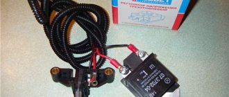
Voltage regulator malfunction
Sometimes the so-called “chocolate” fails.
How to determine if the voltage regulator is faulty? Symptoms - the generator gives an excess or insufficient charge. The battery often boils or does not charge at all. The battery light is on on the instrument panel. It is worth noting that this is the most common breakdown.
How much do such spare parts cost for a VAZ-2105? The price of the new integral regulator is 150 rubles. Note that it is the same for all classic AvtoVAZ models and even for the Zaporozhye Tavria.
How to determine that the regulator is broken? To do this, you need to start the VAZ-2105 engine with a timing belt and turn on all electrical appliances at medium speed: headlights, stove, interior lights. Next, using a voltmeter, we measure the voltage level on the battery itself, and then between the output terminal and the ground of the generator. If the readings are from 12.5 to 14 Volts, then the element is working. If the values are too high or low, the voltage regulator must be replaced.
Replacement and removal of the electric generator
The generator on a VAZ car is removed either for complete replacement in case of failure or to carry out repair work to replace faulty parts. To perform dismantling, prepare a standard set of tools; it is advisable to drive the car into the inspection hole.
- Disconnect the battery.
- Remove the protective rubber cap from terminal “30” and unscrew the nut and remove it from the wire stud.
- Disconnect the block with wires from the generator connector.
- We loosen the tightening of the generator to the adjusting bar, then lift it all the way up to the cylinder block and remove the belt from the pulleys.
- Completely unscrew the bolt securing the adjusting bar to the cylinder block, then from the bottom of the car unscrew the 2 bolts securing the lower bracket to the block and remove the generator, pulling it out of the engine compartment.
Source
On-board network elements
The generator is an important part of the electrical system. This is the vehicle's main source of voltage. The generator converts the mechanical energy of the engine into electrical potential.
The stability of the on-board network voltage guarantees trouble-free operation of all consumers. The normal voltage level depends on the following elements:
- Generator.
- Battery.
- Relay-voltage regulator.
The electrical circuit is one whole. Failure of wiring or a short circuit can lead to failure of the entire system. The generator does not work - the battery charging current disappears. The battery is dead - you can't start the car.
The serviceability test can be carried out independently and at home. Typically, such a procedure does not involve dismantling devices on a Zhiguli-2105, 2107 car. It is necessary to have a tester that measures voltage, winding resistance, and the serviceability of diodes.
Connection diagram and repair of the VAZ 2105 generator
This is the unit we are talking about
To provide electrical energy to the electrical appliances of the VAZ 2105 car, as well as to recharge its battery while the engine is running, there is a generator in the car. Until 1987, the VAZ 2105 was equipped with units of the G 222 model, and later with the 37.3701 model. In both cases, the generator is a three-phase electrodynamic device in which the sinusoidal voltage of each phase is rectified using a built-in rectifier. This part is a three-phase diode bridge of a VAZ generator, consisting of six silicon diodes. The voltage is produced by exciting the rectifier by the three stator windings when the rotor poles change underneath them. The rotor poles change polarity as it rotates inside the stator, and to increase the value of magnetic fluxes, it has an electromagnetic excitation winding inside the magnetic cores. The rotor rotates through a belt drive from the front pulley of the engine crankshaft (injector) together with the pulley of the cooling system pump.
List of all articles to search
The generator is still produced as spare parts for cars that remain in use.
Due to the high wear and tear of the fleet, the generators of most cars are very worn out and require repair or replacement with new ones.
The generator was produced by the KZATE plant and in Bulgaria they are completely interchangeable, however, the parts of the generators have different sizes and are not suitable for repairing each other. G 221 is designed for a load of 45 Amps. A working generator ensures normal operation of the standard electrical equipment of Zhiguli cars.
The generator has a conventional circuit - a stator winding, an electromagnetic rotor and a diode bridge. The brush assembly supplies excitation current to the rotor. The voltage regulator is external, installed separately in the engine compartment.
Operation of the G221 generator
When the ignition is turned on, excitation current flows from contact 15\1. This current flows from the battery, through fuse 10, pin 15, voltage regulator, then through the regulator transistor, pin 67 of the regulator and then through the brushes into the excitation winding and to ground.
The voltage regulator controls the excitation current. The emf of the generator increases, the regulator turns off the excitation current and the emf falls, the regulator turns on the excitation current again, the emf increases again. This happens all the time. The regulator operates in the on-off mode, increasing or decreasing the excitation current and, therefore, the voltage at the generator output. With frequent switching, the rise and fall of the voltage is negligible, so the voltage remains almost constant. Voltage surges and dips are additionally smoothed out by the battery.
Generator warning light operation.
On a Zhiguli car, to monitor the operation of the battery-alternator system, there is a red light on the instrument panel, which lights up when the generator is not working. To control the light bulb, a special RS 702 relay with normally closed contacts is installed.
If the generator is not working, the relay contacts are closed, the current flows from the battery through fuse 9, relay point 87, through the closed contacts to the light bulb. The light is on. When the generator starts working, a current appears in the RS 702 lamp shutdown relay and it goes out. For the driver, this means that the generator is working normally. Unfortunately, the light does not light up when recharging
, when the voltage, due to a breakdown of the regulator, can increase to 16 Volts, while the battery will begin to boil away and the light bulbs will begin to burn out.
The light will only go out if the generator is running
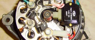
Features of the generator device
The generator housing consists of two covers made of aluminum alloy, tightened with four bolts and nuts, between which a round stator core is clamped. Rotor bearings are installed in the covers: the front one is in a through bearing, the rear one is in a blind seat of the cover. The rotor rotates inside the stator and housing on two bearings. The front end has a slot for a key and a thread for the fan nut. An adjusting washer is installed between the front rotor and the front bearing, which is often forgotten to be installed when repairing the generator. At the rear end of the rotor shaft, in front of the rear bearing, two copper slip rings are pressed in, insulated from the shaft and connected to the ends of the field winding.
A BPV6-50 rectifier is installed to the inside of the back cover. It consists of two horseshoe-shaped aluminum buses insulated from each other, into which three silicon diodes (valves) of the BA-20 type are pressed. The internal bus is isolated from the housing, but is connected to the generator terminal bolt “30”, while the other has contact with ground. The legs of the diodes in pairs from each bus are bolted to the ends of the phase windings of the stator, and their other ends are connected together - a star connection. In the G 222 generator, a wire goes from this point to a terminal on the back cover, from which a wire goes to terminal “85” of the RS-702 type charge indicator relay. There are no wires at 37.3701 from the common point of the phase windings.
Brushes are pressed to the contact rings of the rotor by springs, one of which is connected to terminal “B”, and the second to terminal W of the voltage regulator installed on the brush assembly in the upper rear part of the generator. In 37.3701 there are three diodes connected at one end to the phase windings, and the second are connected to one point, the wire from which goes to the regulator relay terminal Sh and terminal “61” on the rear surface of the generator. The diodes are connected in such a way that they pass positive half-cycles to pin “61”.
The electronic voltage regulator is non-separable and since 1996 has been installed in a metal case riveted to the brush holder. A capacitor is mounted between the housing and terminal “30”.
Generator connection diagram
To control the battery charge level in a VAZ 2105 car, it is necessary to monitor the output rectified voltage, which is maintained within 13, June 14.2 V. The regulator relay compares the voltage in the vehicle's on-board network with the reference one and, if this level is exceeded, reduces the voltage on the exciting winding , increasing the resistance between one of the rotor brushes and the “ground”. When the voltage in the vehicle network decreases, the regulator lowers the resistance, increasing the current in the field winding and, accordingly, the voltage at terminal “30”. Such cyclic processes occur at a frequency of 50-250 times per second.
Comments and reviews
The generator rotor, which is an electromagnet with one winding located on the rotor shaft. Pressure is applied with a mounting blade in the middle of the segment.
Since AC generators have many advantages over DC generators, this was the reason for the choice.
From the moment of its creation until the year, the VAZ was equipped with an aggregate G, after a year this generator model was replaced with a device. By the way, the cover is not so easy to put in place, it is easier to glue a piece of rubber to it so that it does not rattle and then the lamp goes out. Actually, here it is. To remove the drive belt, move the unit slightly. As the rotor rotates, a voltage appears at the output of the stator coils, which begins to power the excitation winding, consumers and charge the battery.
Increased noise during operation of the generating set. The bearings have become unusable. In addition, an additional gas tank and battery were installed. Produced from year to year.
DIY connection diagram for the VAZ-2105 generator (carburetor, injector): video instructions
To protect the cover ears from breaking when tightening the bolts, a rubber buffer sleeve is inserted into the hole in the cover ears 1. Otherwise, check the windings and rectifier of the unit. To control the battery charge level, you need to carefully monitor the amount of rectified voltage, maintained around 14.2 V.
If the resistance has a low value, close to zero, it means that a breakdown has occurred in the diode bridge or the stator winding has shorted to ground. The lamp goes out, indicating that all devices are powered by the generator. Now the battery received a voltage of more than 15 V, which led to the boiling of the liquid in it. However, after purchasing and installing a new regulator, another problem arose - battery overcharging.
The regulatory relay compares the voltage within the on-board network of your car with the reference one. Rear marker light left lamp. Headlight wiper relay relay coil. Excessive wear will indicate that the damaged belt needs to be replaced. Repair of generator VAZ 2107