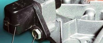
Error P0500 symbolizes a malfunction in the vehicle speed sensor or its electrical circuit (“Speed Sensor Error” or in English - Vehicle Speed Sensor). Moreover, this error occurs on cars equipped with an anti-lock braking system (ABS), which prevents the car from skidding. The fact is that the operation of the mentioned system is controlled by the electronic control unit (ECU) of the car, in particular, it compares the speed of rotation of the crankshaft and the wheels themselves. A four-pulse signal with relevant information passes through the ECU. To generate error P0500, five conditions must be met simultaneously.
As for diagnosing the P0500 code, you can do it yourself, with only an electrical tester (multimeter) and basic plumbing tools. As practice shows, error code P0500 often results from a break in the signal wire or a critical decrease in the value of its insulation (simply put, it is frayed). According to statistics, a similar error occurs more often than others in the following car brands: Toyota, Ford, VAZ, Peugeot, Chevrolet and Opel.
Technical description and interpretation of error P0500
This diagnostic trouble code (DTC) is a generic powertrain code. The P0500 code is considered a common code because it applies to all makes and models of vehicles. Although the specific repair steps may vary slightly depending on the model.
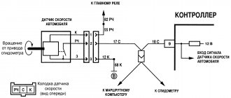
The P0500 OBD2 trouble code indicates that the vehicle speed read by the Vehicle Speed Sensor (VSS) “A” is not as expected. The Vehicle Speed Sensor (VSS) provides information to the ECM (engine control module) about vehicle speed. To display speedometer and odometer.
To do this, it produces a signal of 4 pulses for each revolution of the rotor shaft, which rotates the output shaft through the driven gear. Typically, the VSS is an electromagnetic sensor that uses rotation to transmit a signal to the ECM.
The VSS is installed in the gearbox housing in such a position that impulses from the gearbox can pass in close proximity to it. When the box pulses pass by the VSS electromagnetic tip. Notches and grooves serve to quickly close and interrupt the circuit.
These manipulations are recognized by the PCM as transmission output speed or vehicle speed. This allows us to see the usual display of speed on the speedometer.
Passion around code P0500
It would seem that what is incomprehensible here? It turns out that everything is clear, but when searching for the fault that generated this code, you can go far. Therefore, I’ll start with how the problem was fixed on a Toyota Avensis car. Code P0500: “The computer does not receive the speed sensor signal.” Happens. But the owner's story makes me think. The last option was to replace the ABS unit. “All the wiring has been checked, the thresholds have been opened”... when you hear this, at first you tense up... because then you can expect anything. Therefore, in order to prevent the client from continuing the story and creating fear, I usually interrupt such a story with a question. Any question can be asked, the main thing is that it is in the vein of the conversation, but interrupts the train of thought and confuses the narrator: - Cover... lid? No. — Okay, it’s the end of the working day, you can leave the car. You'll pick up the car tomorrow.
The check is, in principle, standard for all Toyotas with this code. Described everywhere; by steps, by control points, with data and signal shape.
I use MOTORDATA information, an oscilloscope, a multimeter scanner. Photo 1:
Photo 2:
Photo 3:
Let's start checking, photo 4:
Having checked the errors in the car’s systems with a scanner, I take oscillograms. On the first channel SPD of the ECU, on the second channel SPD of the instrument panel, the third channel is the right ABS sensor, the fourth channel is the left ABS sensor. The car is suspended on a lift, the engine is running.
On channels No. 1 and 2, a reference voltage of 4.6 V is visible, of course there is no signal, the gear is turned off, the wheels do not spin. Photo 5:
We turn on the transmission. The drive wheels begin to rotate. The SPD signal appears on the first and second channels. On 3 and 4 signals from ABS sensors. Sensor signals are primary information about the speed of rotation of the drive wheels. From which, through simple transformations, a speed signal is obtained. And in Fig. 2 everything looks “delicate and noble”, everything works. But does the error come from somewhere?.. here you need to either wait, monitoring the signals, or try to provoke the error to appear.
What caused error P0500 to appear is as follows, photo 6:
The same XX, the gear is engaged, there is a short-term loss of signal from the instrument panel, and, accordingly, to the ECU. And ABS sensors, as you can see, conscientiously perform their assigned duties. I changed the sweep time in this picture so that the moments where the signal is present, where it disappeared and where it reappeared were visible. Here is a pure error P0500. The reason is inside the instrument panel. And it was fixed with a few pokes of a soldering iron. True, you need about. Also, record the oscilloscope data. Then you can look at it carefully. Sometimes you’ll look through it and you’ll find something else that catches your fancy-).
So we continue with the same Avensis... although I didn’t see this error. And the client didn’t mention it. He said that before changing the ABS block, they checked all the sensors and cleaned all the “readers”.
Anyway, while looking at the waveform, I saw something else. Photo 7:
The engine is running, XX, the car is on a lift, the gear is engaged, the drive wheels are rotating. Markers highlight a time period on the pulse sequence of channel No. 3. And it corresponds to the same time period on channel No. 4. Must match. But they don't match. And not only in phase, but also with the amplitude of the signal, not everything is clear either. Only one thing is clear: with such sensor signals that record the speed of rotation of the drive wheels, it should be visually visible that the wheels rotate at different speeds. The fact that the wheels may not rotate at the same speed due to wheel bearings or caliper wedging is understandable. But that's not it. Visually, the drive wheels rotate at the same speed. This means that we need to identify which of the sensors is lying.
From a picture like this, it’s impossible to tell which one is which. Therefore, we will change the picture. Photo 8:
We increase the speed. Now you can see that the ABS ring of the left sensor is “dangling”... but in principle there will be no error. The system will “tolerate” this -).
Well, what if you “anneal”?.. the car is on a lift, the traffic police is not a decree, the “trigger” is on the floor, photo 9:
I don’t change the scan along the way, so the signals from the sensors actually merge and the grid shows that the amplitude is now at least 2 Volts. So far the flight is normal.
We accelerate further, photo 10:
Oops! The signal from the left sensor floated. The right one is normal. And on the left, the amplitude decreased by almost a third. And from the “humps” of the signals it is clear that the time of the periods is different, which means that the speed of rotation of the left wheel has become less and much less... But visually, no-). And the speedometer shows 140 km/h.
Let's look further, photo 11:
And here you can see how it slowly and surely fades, photo 12:
I lowered channel 4 below the background of the right sensor so that it could be seen that there is no signal from the left sensor, but the wheels are spinning, there is an SPD signal, and there is a code for the left ABS sensor Photo 13:
Here the engine reaches idle, the pedal is released and the missing signal appears. If this can be done on a lift, then the same error will definitely appear while moving. It was possible, of course, not to pay attention to this; this is not why the person came. Well, I saw it, well done. Send him, he will return to you. But I'm not a marketer - I'm a techie. And artificially attracting clients is not my bread. Moreover, this method contradicts moral principles. No, this is not a statement: “I don’t need money.” I just consider it humiliating to make money in this way... even if only you know about it. And if I fixed the first fault myself, then to fix this one I resorted to the help of a guy who works as a mechanic. He explained that the ABS ring needed to be put back in place, but it was when the drive rotated that it broke off and rotated on its own. And at high speed, the CV joint on which it was mounted rotated as it should, and the ring, not having “reliable contact with its surface,” simply stopped. And the sensor did not receive a signal about wheel rotation. A wonderful oscilloscope device. Two hits with a hammer on the core - the ABS is fixed -).
When I hired Avensis, a topic was created on the forum specifically for the code P0500. And specifically at Toyota: https://forum.autodata.ru/264/23671/
Well, naturally, I keep an eye on the topics. I don’t particularly interfere anywhere. People advise something. Offers something. There is a usual exchange of opinions. As a result, the topic came to the point where a person fixed the problem... Replacing the ABS unit. Some were frankly puzzled by this... questions followed, but then explanations followed... I “put in my 2 cents too,” but the result was somewhat unexpected, there was some deviation from the topic. When I wrote posts on this topic, I provided the same oscillograms, but did not describe them in such detail, and tried to explain that this code is designated “P” «,
which determines its belonging to a particular system. And ABS fault codes are somehow designated by a different letter -).
I took the computer with me into the car, opened what I needed, everything was in front of my eyes, the information completely satisfied my needs. But, and if suddenly I didn’t find something, then on the same computer there is access to TechDoc, Alldata, Mitchell, but I rarely use the latter. Online access is convenient. And I brought screenshots from Motordata.
Here they are, photo 14:
Photo 15
Photo 16:
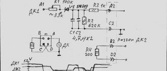
I was brought back to “reality” by posting a fragment of the diagram, photo 17:
The diagram was taken from the forum.
And then came the “horror story”: the 2012 Toyota Coroll HAS CAN! …
And what? ... need to look at the information. I looked. Doesn't change anything. There is CAN, but it has nothing to do with the situation described in the topic. The speedometer on the car worked, the instrument cluster cannot have any influence on the presence or absence of the SPD signal to the engine control unit. The signal still comes from the ABS. The source of primary information was and still is the ABS sensors of the driving wheels. Therefore, when searching for the malfunction that caused code P0500, all possible control points and locations of possible malfunction remained the same. But there is a peculiarity. It lies in the fact that in the ABS block, which processes the signal from the system sensors and transmits it to the control panel, this signal is digital.
Why did they do this? If you look at the fragment of the diagram that was taken from the forum, then even from it it becomes clear that there are design changes in the instrument control panel. The panel collects information about the operation of various systems. In particular, about on/off, etc., etc.... doors, hatch, ashtray -). The goal is to inform the driver.
It is possible, of course, by wire, but in digital form this information is more attractive, since it does not increase the thickness of the harnesses and does not increase the number of connectors. There was some confusion on the forum thread. A story followed about how to watch the SPD signal. It turns out that you also need to connect to the controller’s leg... And here I personally had a question: “What for is a goat button accordion?”
Motordata (https://motordata.ru/ru) gives a comprehensive answer to where and in what places you need to look for a fault with code P0500. Topicstarter, which created the topic and described the problem, went wrong. It was not checked systematically. And replacing the ABS block, which cleared this code, is only a consequence of the fact that a bad contact has been eliminated somewhere. According to the data he posted, the unit worked. Another discussant in the thread took the conversation astray. I posted the oscillograms and for some reason went in the direction of the controller. Even on one channel the guy’s leg was caught. How are we on the forum? If someone wrote: - “CAN…. Either the leg of the protek or the protek” - that’s it, the majority immediately became silent. And they don’t even try to understand what’s written... Let’s summarize:
1. When code P0500 occurs, this code is related to the engine management system. Its meaning is simple: “The ECU does not see the vehicle speed signal.” The reasons are listed, as well as possible locations. Step-by-step search instructions are available.
2. The method for troubleshooting using this code is no different for Toyotas.
3. The speed signal actually passes through the instrument panel (there was a question about this signal: “where does it come from?” There was no clear answer, so I answer:
“All microcontrollers include an analog comparator module. The comparator compares the voltage values present at the two pins of the microcontroller. The result of the comparison is a logical value. Using this value, both an interrupt and a state capture of the counter-timer can be generated. And this allows you to measure the duration of pulses of an analog signal. Therefore, the ECU reference voltage changes from a minimum to a maximum level, forming a pulse sequence containing information about the vehicle speed. And even if one sensor fails, the unit still receives speed information. This signal can be traced in two places at the output of the general purpose port and at the output of the control panel itself.
The timer actually duplicates the operation of the sensors and retains all the information contained in the original signal.”
, photo 18.
4. In cars where information comes to the instrument panel via the data bus (CAN) ... including from ABS, there is a difference: the speed signal from ABS comes to the panel in the form of a digital code. And in the instrument panel, signals from sensors are not compared. But the timer-counter state is also captured. The timer simply generates interrupts using a digital code that contains information about speed. The reference voltage of the control unit will also change amplitude from maximum to minimum level, forming a pulse sequence of the speed signal.
5. The additional elements introduced into the ABS, instrument panel, and data buses are fully controlled. Additional codes C….. and U…… have appeared in the diagnostic system. These codes directly indicate a malfunction in ABS, CAN and the control panel. The appearance of these codes can cause the P0500 code to appear. As an option: replacing the ABS unit and the disappearance of this error is quite understandable. But in this case, the ABS code will be dominant. The same applies to the instrument panel. If the P0500 code is as lonely as “poplar on Plyushchikha,” then there is no need to invent anything, much less cling to the controller’s legs. 6. Considering that data buses are increasingly being used in new cars, it is probably right to start checking by identifying the systems of a particular car, as well as the presence of errors in them. In order not to look for “tomorrow”... it would be more correct to deal with what is today.
7. You should not be skeptical of those who are guided by official information and are inclined to step-by-step verification. There is nothing wrong with this. Although, when I had to deal with this issue, I used Alldata. I opened the 2012 Corolla. And by the time I got to the necessary diagrams, I was grinding my teeth... Well, it’s so detailed that by the time you get to the necessary information... everything is step by step, with pictures.. But it’s hard to make a mistake, though you may not even find the fault -).
And I would also like to note that there are people on the forum who repair cars. And none of us have complete knowledge on this issue. There are fragmentary ones. Some have more of these fragments, some have less. Some people have basic knowledge. This is what needs to be taken into account during discussions. And if a question is asked, it must be answered. Without emotions and grins. Especially if you yourself diverted the topic and provoked these questions. And answering a question with a question is disrespect for the interlocutor. Therefore, in a thread on the forum, I promised that I would answer questions... and I will do it a little later.
We need to figure it out: - are there sensors that generate a digital signal or not; — what is CAN. Why you shouldn’t be afraid of it and how to check it; — is it necessary to go to the controller in search of the desired signal or are standard checks sufficient? - how does a digital signal differ... And how not to confuse it with a regular pulse sequence of rectangular pulses, can it be seen and is it necessary; - about signal conversion from ABS (as a special case) - about fragmented ranks, and why this can cause harm.
To be continued.
Markin A.V.
© Legion-Avtodata
(nickname on the Legion-Avtodata forum - A_V_M) Belgorod, Tavrovo microdistrict 2, Parkovy lane, 29-b.
Tel..
Union of Automotive Diagnosticians
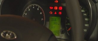
Symptoms of malfunction
The main driver symptom of a P0500 is the MIL (malfunction indicator light) illumination. It is also called Check engine or simply “check light”.
They can also appear as:
- Disables the vehicle's anti-lock brake system (ABS) and traction control system (TCS).
- The warning lights (ABS) or brake lights on the dashboard may come on.
- The speedometer or odometer may not work correctly or at all.
- The vehicle's rev limiter may be lower than normal.
- An automatic transmission may experience problems when shifting gears.
- Other symptoms may be present.
Basic error codes for VAZ 2114 injector: decoding
Note!
The table is also relevant for version 2115.
Exhaust system – 0000
- 30 – open circuit of the oxygen sensor heater to the catalytic converter;
- 31 – also with a short circuit to the car body;
- 32 – similar with a short circuit to 12V;
- 36-38 – the same value as 30 only for the output sensor.
Air line defects – 0100
- 102/103 – Mass air flow sensor open circuit or signal violation;
- 112/113 – sensor lines t˚ overboard, impulse violation;
- 116 – engine overheating;
- 117/118 – damage to the DTOZH circuit;
- 122/123 – TPS line, short circuit or insulation failure;
- 130 – failure of the oxygen sensor in front of the catalyst;
- 131/132 – similar element, signal level violation;
- 133 – slow response of DK1 to commands;
- 134 – break in the power cable DK1;
- 136 – DK2 is broken;
- 137/138 – short circuit or violation of wiring DK2;
- 140 – fuse DK2 burned out;
- 141 – the heater of the same device is broken or damaged;
- 171/172 – excessively lean or enriched fuel mixture.
Error codes VAZ 2114 1.6 liters related to fuel supply - 0200
- 201/204 – break in the injector control line for all injectors in series;
- 217 – motor overheating;
- 230 – the fuel pump has failed or the corresponding relay has burned out;
- 261/264/267/270 – short circuit of the injector control circuit at +12 V, respectively, for each insert;
- 263/266/269/272 – failure or defect of the injector driver for each in series;
- 262/265/268/271 – Short circuit of highways to the car body.
Error codes on the VAZ 2114 on-board computer indicating a breakdown in the ignition system - 0300
- 300 – there are misfires;
- 301-304 – similarly for each cylinder, respectively;
- 326-328 – DDS is broken or there is no signal;
- 335-338 – failure, short circuit or interruption of the DPKV wiring;
- 342/343/346 – malfunction of the phase distribution sensor;
- 351-354 – open circuit for all pistons in series;
- 363 – the mixture in the cylinders does not ignite, emergency fuel supply cut-off.
Additional attachment that does not have a direct effect on the motor – 0400
- 422 – the catalyst may have clogged or the exhaust gas flow rate has dropped critically;
- 441 – failure of power supply to the adsorber purge valve;
- 444 – power failure above the specified element;
- 445 – short circuit of the gearbox to the car body;
- 480 – power wires to the main radiator cooler are damaged;
- 481 – failure of the coolant fan control circuit No. 2.
Failure, malfunctions in the SU speed control system – 0500
- 500 – speedometer sensor is broken;
- 506/507 – low or high speed of the vehicle;
- 511 – XX regulator – lines from the relay and ECU are interrupted;
- 560 – the battery is low or the power cable is broken.
- 562/563 – Short circuit on on-board wiring.
On-board network of auxiliary or main equipment – 0600
- 601 – ECM, ROM error;
- 615 – secondary starter relay, wiring damage;
- 616/617 – also with short circuit to ground or 12V;
- 627 – fuel pump control relay, possible line break;
- 628/629 – similar with a short circuit to the body or on-board system;
- 645-647 – compressor clutch, damage to the wiring with contact with the housing or other cables;
- 650 – the “Check Engine” lamp is broken, check the engine, there may be damage to the wiring;
- 654 – tachometer failed;
- 685-687 – malfunction of the main engine control relay, complete replacement of the part is required;
- 691/692 – problems with the main cooling fan relay.
Auxiliary systems – 1000
- 102 – breakdown of heater DK1;
- 115 – failure or malfunction of the above device;
- 123/124 – violation, too rich/lean mixture at idle;
- 127/128 – similar, only for partial load on the internal combustion engine;
- 135 – rupture of heating line DK1;
- 136/137 – incorrect fuel supply at low engine load, the throttle drive may be malfunctioning;
- 140 – discrepancy between measured and actual load;
- 141 – failure of heater DK2;
- 171/172 – incorrect information comes from the potentiometer;
- 301-304 – the ignition in the cylinder does not work correctly, consistently for all combustion chambers;
- 386 – incorrect sequence of testing the detonation channel;
- 410/425/426 – wiring of the canister purge flap, short circuit or line damage;
- 500 – the fuel pump relay line is damaged;
- 501/502 – similarly with a short circuit to the body or wiring;
- 509/513/514 – control center of the XX regulator, open or short circuit on board or 12V;
- 541 – damage to the wire of the BN relay, possible oxidation of the terminal;
- 570 – break in immobilizer control cables;
- 602 – no power to the ECM, oxidation of the pads is allowed;
- 606 – the bump sensor is broken, the part needs to be replaced;
- 616/617 – similarly with a change in signal level, there may be a short circuit inside the device;
- 2301/2303/2305/2307 - the ignition coils are shorted to 12 volts, in series for each piston.
Important!
Only the most popular error codes for the dashboard of the VAZ 2114 and similar models are listed here. There are other indices, but due to their low prevalence they are not mentioned.
Reasons for the error
A P0500 code may mean that one or more of the following problems have occurred:
- The Vehicle Speed Sensor (VSS) "A" is not reading properly and therefore has insufficient readings.
- A broken or worn wire leading to the vehicle speed sensor.
- Poor connection in the Vehicle Speed Sensor (VSS) circuit.
- The vehicle's PCM is not correctly configured for the actual tire size being used.
- Damage to the speed sensor drive gear.
- The engine control module (ECM) may be faulty.
Self-diagnosis
In a car, the operation of the entire electronics system is monitored by a control unit (ECU). In order for the driver to recognize operational failures in time and localize them, cars leave the assembly line with an already built-in diagnostic system. It is located on the front panel. With its help, the system itself detects failures in electronic devices and notifies about them, generating errors with digital codes or their combinations. In this way, the car self-diagnosis occurs. To be able to decipher error codes, special tables have been compiled. In this case, self-diagnosis is carried out on the instrument panel, and not on the computer.
To check, you need to reset the daily mileage data on the wheel revolution meter (odometer), then activate the ignition (position 1).
On all touch devices, the arrows will move twice to the highest readings.
By pressing the odometer button again, messages are received about the installed version of the operating system. The next time you press the button, an indication of problems, if any, is displayed.
What errors may appear during self-diagnosis of the control panel, and how to decipher them
0—indicates that there are no problems with the electrical wiring, apparently the fault is mechanical;
1—indicates malfunctions of the ignition system microprocessor;
2 - no signal is detected coming from the circuit leading to the fuel level sensor. Reason: open circuit, plaque formation due to oxidation of contacts or short circuit;
4—signal of increased voltage in the on-board network (more than 16 V). It is necessary to check the battery and generator;
8—opposite signal, the voltage is too low (less than 8 V) due to a low battery or problems with the generator.
If there is not one malfunction, but a group, then an error is displayed on the dashboard, the code of which consists of several digits resulting from the summation of errors. So, for example, the issued error code 10 indicates errors 2 and 8, 6 – the sum of 2 and 4, 12 – 4 and 8, 14 – 2,4 and 8.
Let's continue decoding:
12 - a malfunction in the circuit leading to the malfunction indicator lamp, possibly due to damage to the connector contacts or their oxidation, or the indicator itself is faulty;
13 - no data is received from the oxygen concentration sensor device (ƛ-probe). The sensor or the wiring leading to it may be faulty;
14—the coolant temperature in the cooling system is higher than normal. Reasons: sensor failure, low fluid level in the radiator, faulty thermostat;
15 - coolant temperature is below normal. Reasons: a failed thermostat, air entering the system due to a coolant leak;
16 - the voltage in the on-board network is too high;
17 - the voltage in the on-board network is too low;
19 - fault in the wiring of the PCV sensor. Reasons: oxidation or contamination of contacts, broken wiring, short circuit, mechanical failure of the wheel;
21-22 - error in the position of the remote sensing sensor, due to a failure of the electronic part, due to a breakdown of the movable core or due to the fact that the coating on the slider has been worn off;
23-25 - deviation from the norm of the intake air temperature sensor. Possible reasons: clogged sensor element, oxidation of contacts, open circuit, short circuit;
How to Troubleshoot or Reset Trouble Code P0500
Some suggested steps to troubleshoot and fix the P0500 error code:
- First, read all stored data and error codes using an OBD-II scanner.
- Then clear the error codes and test drive the vehicle to see if there is a problem.
- Next, check the vehicle speed sensor and all related wires for wear or damage.
- Also check for the presence of a speed sensor signal while the car is moving using a scanner.
- If the above problems do not exist, check the vehicle speed sensor voltage using a multimeter.
Necessary conditions for diagnosis
To obtain an accurate result, 4 conditions must be met:
- 80 degrees Celsius - this should be the temperature of the cooling medium;
- 1600 rpm - indicator of the angular speed of rotation of the crankshaft;
- speed - less than 5 km/h, in some cases - up to 10 km/h;
- exceeding TL by 3 milliseconds.
If these conditions are met for 4 seconds, the Check Engine icon will appear on a car with automatic transmission. On vehicles equipped with a manual transmission, the error can only be detected if these conditions are met twice, that is, the second time.
Diagnosis and problem solving
The first step is to look for Technical Service Bulletins (TSBs) for your specific brand of P0500 vehicle. If the existing problem is not described, following the instructions can help you save time and money in diagnosing and fixing the problem.
Visually inspect all wiring and connectors leading to the speed sensor. Carefully inspect for any abrasions, exposed wires or breaks. Also look for melting or other damaged areas. Repair if necessary.
The location of the sensor depends on your car; it is not always installed in the box. It may be located on the transmission rear axle or wheel hub (brake) assembly.
If everything is in order with the wiring and connectors, then check the voltage at the speed sensor. Again, the exact procedure will depend on your car make and model. Most likely this is where the problem lies, so replace the sensor.
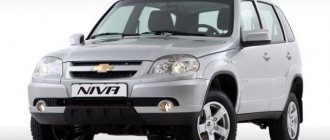
Chevrolet Niva error diagnosis
The most reliable way to identify what is wrong with a car is to diagnose electrical appliances and equipment. The procedure allows you to accurately identify breakdowns and quickly repair your car.
There are two ways to detect a problem in a car.
Self-diagnosis VAZ 2123
The simplest procedure allows the motorist to independently identify the damaged area and repair the damage. Thanks to the successful firmware of the on-board computer, some errors are displayed on the standard display. In this case, nothing happens on its own - you will need to perform several steps manually:
If the manipulations are correct, one of the indicated codes will appear on the display, and each Niva Chevrolet error number will be responsible for its own section of the highway:
At the same time, you need to accurately understand that, for example, when error 10 is on the display, the Chevrolet Niva tells the driver that there are several problems (standard, unambiguous codes are summed up).
You should also know that Niva Chevrolet self-diagnosis errors do not reflect the exact location of the breakdown. Codings can only show the section of the wiring where you need to look for the cause of the malfunction. Also, these encryptions may be the result of a software failure after an unsuccessful wash or disconnection of the battery. To obtain more accurate data, the user needs to connect a special diagnostic scanner.
On which cars is this problem most common?
The problem with the P0500 code can occur on different machines, but there are always statistics on which brands this error occurs more often. Here is a list of some of them:
- BMW (BMW X5)
- Chery (Chery Amulet)
- Chevrolet (Chevrolet Captiva, Epica)
- Chrysler
- Citroen (Citroen C4, C5)
- Daewoo (Daewoo Matiz)
- Dodge (Dodge Caravan, Stratus)
- Fiat (Fiat Ducato)
- Ford (Ford Mondeo, Transit, Fiesta, Focus, Fusion, Explorer)
- Honda
- Hover
- Hyundai (Hyundai Porter, Santa Fe, Sonata, Elantra)
- Infiniti
- Isuzu
- Jeep
- Kia
- Land Rover (Land Rover Range Rover)
- Lexus (Lexus lx470, rx300, rx330, rx350)
- Mazda (Mazda 3, Mazda 6, Demio, Premasi, Familia, MPV)
- Mercedes (Mercedes Sprinter, w203, w210, w211)
- Mitsubishi (Mitsubishi Karizma, Lancer, Pajero, Tsediya)
- Nissan (Nissan Almera, Maxima, X-Trail)
- Opel (Opel Antara, Astra, Vectra, Zafira, Meriva, Omega)
- Peugeot (Peugeot 206, 207, 307, 308, 607, Boxer, Partner)
- Renault (Renault Logan, Megan)
- Subaru (Subaru Outback, Impreza, Legacy, Tribeca, Forester)
- Suzuki (Suzuki Grand Vitara, sx4)
- Toyota (Toyota Avensis, Auris, Venza, Vista, Vitz, Kaldina, Camry, Carina, Corolla, Crown, Land Cruiser, Mark 2, Platz, Prado, Premium, Rav4, Celica, Fielder, Funcargo, Highlander, Hilux, Harrier, Chaser , Echo, Yaris)
- Volkswagen (Volkswagen Transporter)
- Volvo (Volvo s60)
- VAZ 2105, 2107, 2110, 2112, 2114, 2115
- Gazelle
- Lada Granta, Kalina, Largus, Niva, Priora
- UAZ Bukhanka, Patriot
You can sometimes encounter other errors with the P0500 fault code. The most common are the following: P0036, P0056, P0102, P0130, P0136, P0325, P0444, P0501, P0502, P0503, P0505, P0600, P0700, P0717, P0720, C1408, U1113.
Diagnostics using third-party equipment
More precisely, errors on Chevy Niva can be identified by connecting additional equipment. The technique is more technically complex, but allows us to determine the cause of a breakdown or failure with minimal error. In this case, the sequence of actions is as follows:
- turn off the engine;
- find the contact connector under the dashboard, the connector is located at the bottom of the steering column;
- connect the configured computer to the ECU output;
- turn on the ignition;
- follow the program instructions.
If all actions are performed correctly, all available information and any errors in the form of encrypted codes will be displayed in the desktop window.
There are also specialized scanners designed specifically for Chevrolet NIVA. Dealer devices are connected to the place of the standard signaling unit through an output cable.
Separately, we should highlight modern devices designed to connect a smartphone to a car, while reading encodings and controlling operating modes occurs directly from the gadget’s display.
At the same time, you should know what the encodings displayed during diagnostics mean. The code consists of several elements.
First part:
- P – the motor electronics have failed;
- C – there are problems with the chassis;
- B – interior space, a problem has been detected;
- U – there are problems when establishing pairing of on-board systems.
The next element is a single digit:
- 0 – OBD 2;
- 1-2 – standard code of the manufacturer;
- 3 – reserve part of electrical equipment.
The following digit determines the exact serial number of the line in which the defect was detected:
- 0 – exhaust system device;
- 1-2 – violation of the fuel or air supply device to the engine;
- 3 – ignition does not work correctly;
- 4 – additional equipment control;
- 5 – monitoring the engine idle state;
- 7-8 – transmission and chassis design.