The gearbox synchronizer is a part designed to match the speed of the shaft and gear when changing gears. As the name of the device implies, it synchronizes rotation speeds and ensures smooth (without jerking) engagement of a certain gear. Thus, the gears are engaged smoothly and quietly, and the wear of gears in the gearbox is significantly reduced, increasing the service life of the unit.
Operating principle of the gearbox synchronizer
If a car's manual transmission did not have a synchronizer, then each gear change would be accompanied by loud noise and a sensitive shock. In this case, the driver must guess the rotation speed of the gears of each gear so that they coincide. It is at this moment that it would be necessary to change gears in a gearbox without synchronizer. However, nowadays all manual transmissions are equipped with a synchronizer and this makes life easier for motorists. In this article we will talk about the operating principles of the gearbox synchronizer.
The main purpose of the gearbox synchronizer
A gearbox synchronizer is necessary in order to, by synchronizing the rotation ranges of the wheels and the engine, minimize impacts on the gearbox gears and extend their service life. In other words, the synchronizer equalizes the peripheral speeds of the clutch and gear.
In modern manual transmissions in passenger cars, a synchronizer is required. However, often it is installed only in forward gear. Reverse gear operates without synchronizer. That is why it does not turn on when switching to it at high engine speeds.
Changing gears in a gearbox without synchronizer
On trucks and tractors, gearboxes have up to 15-20 steps. Such gearboxes do not use synchronizers. Professional drivers know how to change gears quite quickly so as not to create delays in the operation of the gearbox. In general, it is believed that a manual transmission without synchronizer lasts much longer compared to a gearbox with synchronizers.
The table below describes the gear shift algorithm in a gearbox without synchronizer.
Step Description 1
Waiting for the moment to compare the values of the peripheral speeds of gears of different stages. Finding this moment is important in order to switch to another gear without jerking and knocking. 2
Quick shift to neutral Depress the clutch very quickly and shift to neutral for subsequent quick transition to a new gear. This method is called “double squeeze”. 3. Quickly shifting to a higher gear Immediately after shifting to neutral, we quickly depress the clutch and shift to a higher gear. At the same time, we increase the engine speed by pressing the accelerator pedal.
The principle of operation of the synchronizer
Thanks to the synchronizer, the gears that are involved in the transition from one gear to another are in a constant state of engagement with each other. This greatly reduces noise from gear shifting and makes the gearbox more stable. This is achieved by locking the gears, which receive torque from the shaft on which they are located.
The synchronizer design includes:
– a hub mounted on the shaft of the movable coupling;
– blocking rings of crackers.
In modern robotic manual transmissions, such as the German DSG, the synchronizer is controlled electronically and by servos. Thanks to this, only eight milliseconds are spent changing gears.
Advice from experts on manual transmission operation
Like any other complex vehicle mechanism, a manual transmission must be operated in strict compliance with the rules of the vehicle manufacturer. Following these simple rules, as the practice of the Favorit Motors Group of Companies specialists shows, can slow down the wear of parts and reduce the frequency of breakdowns in units.
- It is advisable to change gears in accordance with the manufacturers' recommendations regarding the permitted minimum and maximum speeds intended for each gear. In addition, the manufacturer usually provides instructions on how to operate the vehicle economically. For example, for a Volkswagen Polo car (1.6 engine, 110 hp, 5 manual transmission) there are recommendations for economical fuel consumption: switch to second gear at a speed of 20 km/h, to third when reaching 30 km/h, to fourth at 40 km/h and in fifth at 50 km/h.
- Shifting into reverse gear (reverse movement) should only be done when the vehicle is completely stationary. Even at low speeds, shifting into reverse gear is unacceptable.
- It is recommended to depress the clutch pedal quickly and release it slowly and without jerking. This reduces the friction force on the release bearing and delays the need for repairs.
- When driving on a slippery road (ice), you should not drop the clutch or put the gearbox in neutral.
- It is not recommended to change gears during sharp turns; this leads to rapid wear of the mechanisms.
- Any vehicle needs constant monitoring of the amount of oil in the manual transmission crankcase. If the working fluid is not added and replaced as necessary, the oil becomes saturated with metal dust, which increases wear.
As you can see, it is quite possible to extend the “life” of a manual transmission. To do this, you just need to follow all the manufacturer’s recommendations, and at the first doubt about the quality of work, contact the specialists of Favorit Motors Group of Companies.
The company's technical centers are equipped with all the necessary diagnostic equipment and specialized tools for diagnosing faults and repairing manual transmissions. To perform repair and restoration work, Favorit Motors Group of Companies specialists use technologies recommended by the manufacturer and high-quality certified spare parts.
Auto service technicians have many years of experience and specialized knowledge, which allows them to quickly diagnose faults and carry out any type of repair of manual transmissions. Each specialist regularly undergoes retraining at the training centers of manufacturing plants and receives a certificate for the right to repair and service a certain brand of car.
Customers of the Favorit Motors car service can enjoy convenient work hours, online booking for maintenance and repairs, a flexible loyalty program, a warranty on spare parts and all types of manual transmission repairs. All necessary components and consumables are available at the company’s warehouse.
The price of manual transmission repair depends on the type of breakdown and the amount of repair and restoration work required. By contacting Favorit Motors Group of Companies, you can be sure that the functionality of the “mechanics” will be restored as soon as possible, and the cost of services will not negatively affect the family or corporate budget.
Signs of wear on the mechanism
Several things can indicate a breakdown of the synchronizer, and, at first glance, they may also indicate a breakdown of another element of the gearbox. Unscrupulous craftsmen can take advantage of this by insisting on major and expensive repairs of the entire gearbox. A car enthusiast must be able to distinguish between signs of synchronizer failure and those signs that indicate a malfunction of other transmission elements
And here's what you need to pay attention to:
- Arbitrary switching off of any gear;
- Sharp noise when changing speed;
- Difficulty engaging the gear;
- The gear is not switched on clearly or cannot be switched on.
Most often, car enthusiasts complain about the noise that occurs when the gearbox operates. In most cases, it is caused by wear of the cone or bending of the blocking ring. A more serious problem is spontaneous transmission shutdown. Here the problem may be related to both the clutch and critical gear wear. If the gear is simply difficult to engage without applying serious effort, you can safely diagnose a synchronizer failure. The mechanism can be repaired, but practice has shown that installing a new synchronizer is preferable to repairing the old one. However, a car enthusiast can delay the failure of an already installed mechanism. To do this you need:
- Minimize the number of sudden starts;
- Avoid aggressive driving style;
- Change gear oil in a timely manner;
- Depress the clutch fully before changing gear;
- Carry out maintenance on time.
Ideally, the synchronizer lasts as long as the entire gearbox. This is a simple mechanical device in which there is practically nothing to break. Of course, over time, the metal ages and loses its properties, but synchronizers of even quite old cars can properly perform their tasks even in the most severe conditions. If desired, the car enthusiast can still remove the part, inspect and make minor repairs to the mechanism. Let's find out what is needed for this.
Possible malfunctions:
With prolonged, and most importantly, very frequent use of the gearbox (this happens when driving on difficult roads, when you often have to change gears), even if you use it correctly, noise may appear at the moment of gear shifting, clearly indicating a synchronizer malfunction. Most often, this failure indicates wear on the threads of the canonical surfaces of the locking rings, the disappearance of the gap between the end and the ring of the gear, or the lack of friction between the cones of the coupling.
Synchronizer repair involves complete disassembly and subsequent replacement of all damaged parts.
For repairs, you may need a screwdriver with a strong handle and a flat blade and thin-jaw pliers.
Buy spare parts and replace
We buy new spare parts and assemble them in reverse order.
Pay attention to the teeth so that there are no licked edges of the teeth. It is advisable to change in pairs: the sliding clutch of 1-2 gears and the second gear gear
If it is necessary to change the differential bearings, this is done as follows. We take two chisels, insert them into the gap, and knock it out from several sides. We do this until a gap forms between the differential box and the bearing. We insert the spacer, install the puller, and press it together. We install the new one with a mandrel of a certain diameter, preferably made of non-ferrous metal.
In short, this is how a gearbox is repaired. It is better to purchase spare parts from well-known manufacturers, since the durability of the work depends on their quality.
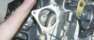
How to assemble a 5th gear synchronizer for a VAZ 2109
Assembling the VAZ-2109 gearbox synchronizer
When repairing the gearbox, disassembling and assembling the synchronizer is required. Unless of course it is completely replaced.
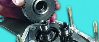
Synchronizer parts: 1 — hub 2— spring 3— holder 4— ball 5— clutch
The grooves for the clamps have holes for the springs.
Before disassembling, mark the position of the coupling relative to the hub.
When disassembling the synchronizer, carefully remove the coupling from the hub, making sure that the spring-loaded balls with crackers do not fly apart in different directions.
Inspect the synchronizer parts.
Chips and nicks on the splines of the hub and coupling are unacceptable (pay special attention to the ends of the coupling teeth).
There should be no damage or signs of binding on the crackers, balls and springs. Replace defective parts.
Install the coupling on the hub so that the three large grooves on the splines of the coupling are opposite the slots in the hub for the clamps.
Lubricate the clamp spring with Litol
Insert the spring into the hole located in the hub groove.
Lubricate the cracker with Lithol and insert the ball into its hole from the outside.
1 - outer side of the cracker (larger surface area) 2 - inner side of the cracker (smaller surface area)
Compress the spring with needle nose pliers.
Insert the cracker with the ball so that the ball fits into the grooves on the coupling splines
Gearbox synchronizer: operating principle
It’s hard to imagine, but automobile gearboxes did not always have a gearbox synchronizer to equalize the rotation speed between the shaft and gear. Previously, in order to change gears, you had to double-depress the clutch. The first is to disconnect the gearbox from the crankshaft, and the second, on the contrary, to connect them after the transmission pair has been changed (speed change).
But time passes. Mechanical engineering and mechanics have stepped into the future. The constant jerking of the clutch pedal was replaced by a gearbox synchronizer, which significantly increased the service life of the gearbox as a whole and its individual components in particular. Driving has also become more convenient for the driver.
What is a gearbox synchronizer?
The gearbox synchronizer device, as well as the VAZ synchronizer itself, is a mechanical unit consisting of 4 parts:
- Synchronizer cage or hub with three clamps;
- Two ring springs;
- Two friction cone rings;
- Shift clutch.
This simple design of the VAZ synchronizer ensures the principle of operation of two gears at once.
How does a synchronization device work?
The main working element of the VAZ synchronizer is its hub, which is connected to the engagement clutch using three clamps and splines cut on it. That, in turn, is connected to the gearbox fork. The hubs are connected to the shaft with internal splines, while having the free ability to move along it from one gear to another.
When it is necessary to switch gears on a VAZ, the gearbox fork moves the clutch, and with it the entire gearbox synchronizer, to the gear whose rotational speed needs to be aligned with the shaft rotational speed. This is where the principle of operation of the synchronizer begins. The clutch presses the entire device against the conical part of the gear. In this case, the clamps on the clutch move and block the friction ring, which comes into contact with the cone on the gear. The friction ring on the cone rotates until it locks. As soon as this happens, the speed between the shaft and gear is synchronized, and the motor is adjusted to the new operating speed.
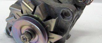
Synchronizer clutch
When did the first gearboxes appear?
There is no exact answer to this question. It is generally accepted that the first gearboxes with a gearbox synchronizer appeared in the late 40s or early 50s. Some claim that this happened in the Soviet Union, while others say that the founder of this innovation was Porsche. Be that as it may, thanks to the advent of the synchronizer, including its operating principle, the foundation was laid for increasing the number of speeds in the gearbox. Already in the eighties, a five-speed gearbox at VAZ became the norm of that time, and in 2012 the same ]Porsche[/anchor] announced the release of a seven-speed gearbox with a synchronized gearbox.
Materials from which the synchronizing device is made
Steel or brass are the two most common materials used to make VAZ synchronizers. Sometimes, most often in high-budget foreign cars or sports transmissions, there are synchronizing devices coated with carbon fiber. This allows you to withstand higher temperatures and reduce noise levels in contact with the gear, which are a consequence of the high-speed engines of sports models.
Friction rings are also made of steel by stamping, for example, for VAZ, or on more expensive gearboxes, by forging them. As in the case of a synchronizer, the friction rings are covered with a protective layer of non-ferrous metals. For example, copper or molybdenum.
Symptoms that the synchronizing device is sick
It's terribly unpleasant when your car starts coughing, sneezing, creaking and barking. Especially when it is related to the gearbox. Most often, faults with the gearbox are associated precisely with the breakdown of the synchronizing device. This can manifest itself in different ways, for example:
- noise during gearbox operation;
- gear shifting, which requires additional effort;
- automatic speed reset in the box.
Of course, these symptoms can be signs of other breakdowns that have occurred with the gearbox, but often the first thing to fail is the synchronizer. You can, of course, carry out preventive work yourself, but when faced with a serious breakdown, it is best to contact a specialist.
https://youtube.com/watch?v=iBl8CsVtGeg%2520
VAZ 5th gear gearbox synchronizer clutch (2108-2112, 2170) assembly
Dear customers, in order to avoid errors when sending the synchronizer clutch for the VAZ (2108) 5th gear gearbox assembly, please indicate your car model and year of manufacture in the “Comment” line.
The gearbox is designed to change the torque developed by the engine in order to obtain different traction forces on the drive wheels when starting the car, accelerating, moving and overcoming road obstacles; changes in vehicle speed and direction; the possibility of driving the car at low speeds, which cannot be provided by the engine, and disconnecting the engine from the transmission for a long time when parked or when the car is moving by inertia (coasting).
5th gear synchronizer clutch 2108 - 1701116-10 - 1 pc.;
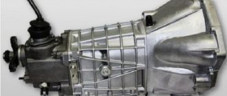
The VAZ 21083 gearbox is a two-shaft, five-speed gearbox, which is combined with a differential and a main gear, and is activated by a lever located in the car's interior.
All modern manual gearboxes, as well as robotic gearboxes, are synchronized. In such boxes, in order to engage the gear, the rotation speed of the shaft and gear is equalized. Synchronization is provided by a device of the same name - a synchronizer.
In addition to smooth gear shifting, the synchronizer reduces wear on the mechanical connection, noise during shifting, and thereby increases the service life of the gearbox.
All transmission gears of a passenger car, including reverse gear, are equipped with synchronizers. The operating principle of the synchronizer is based on the use of friction forces when equalizing speeds. The higher the difference in the rotational speeds of the shaft and gear, the greater the friction force must be to synchronize them. This condition is achieved by increasing the contact surface area - by installing additional friction rings.
The synchronizer consists of a hub with nuts, an engagement clutch, a locking ring and a gear with a friction cone. In a gearbox design, one synchronizer serves two gears (gears).
1. locking ring; 2. hub; 3. cracker; 4. ring spring; 5. gear friction cone; 6. gear; 7. locking ring; 8. synchronizer clutch; 9. cracker; 10. gear.
The structural basis of the synchronizer is the hub. It has internal and external slots. Using internal splines, the hub is connected to the secondary shaft of the gearbox and has the ability to move axially along it in different directions. External splines connect the hub to the engagement clutch.
Three grooves are made along the circumference of the hub at an angle of 120°, into which spring-loaded crackers are installed. In the synchronizer, the nuts press the locking ring when the gear is engaged and help lock the clutch during the synchronization stage.
The engagement clutch (another name is the synchronizer clutch) provides a rigid connection between the shaft and gear. The coupling is mounted on the hub and has internal splines. The splines have an annular groove in which the projections of the crackers are placed. Externally, the synchronizer clutch is connected to the gearbox fork.
The locking ring ensures synchronization and prevents the clutch from closing until the speeds of the shaft and gear are equalized. On the inside, the locking ring has a conical surface that interacts with the friction cone of the gear. On the outside, the blocking ring has splines that are used to block the engagement clutch.
On the end surface of the blocking ring on the hub side there are three grooves into which the hub blocks fit. The grooves prevent the ring from rotating when it comes into contact with the friction cone (the cracks rest against them). The size of the grooves is 1.5 times the size of the crackers. In some synchronizer designs, on the contrary, there are protrusions on the blocking ring and grooves in the hub.
To increase the contact surface and reduce the effort when shifting gears, multi-cone synchronizers are used: two-cone, three-cone. For example, in a three-cone synchronizer, in addition to the blocking (outer) ring, an inner and intermediate ring are also installed. To prevent rotation, the rings have protrusions that are fixed in the grooves of the gear and the blocking ring.
Synchronizer repair
No one can guarantee that the device will not fail. In this case, there is a need for immediate repair. It should be immediately noted that the operation of the synchronizer is not directly related to the functionality of the clutch, therefore, there is no need for replacement. If you are concerned about any problem, you should contact the official dealer of cars of this brand. If you have sufficient knowledge and practical skills, you can try to make the adjustment without outside help.
In some cases, the situation can only be corrected by replacing the synchronizer. This procedure is carried out in several stages:
- Disconnect the gearbox from other parts.
- Clean all surfaces from foreign particles.
- Remove the bracket.
- Disconnect the gearbox plug from the gearbox by unscrewing the nut holding these elements together.
Installation of a new and working device is carried out in the reverse order. An experienced technician could change the device in a matter of minutes.
Signs of breakdown/wear of the synchronizer or its individual parts
Transmission problems often look the same, although they have different causes. Please note that if the owner is not familiar with the structure of individual components of the car, unscrupulous craftsmen can take advantage of this. For example, instead of repairing or replacing the gearbox synchronizer, they may offer to replace or overhaul the entire gearbox.
To avoid unreasonable expenses, it is worth knowing what signs indicate possible malfunctions of the gearbox synchronizers. Synchronizer problems may be indicated by:
In order to check the synchronizers, you will have to disassemble the gearbox and try to move them by hand. The coupling should move easily along the splines. If you have to make an effort or you can’t move it, then you need to remove the synchronizer and disassemble it to inspect the surfaces of the parts for damage. If necessary, worn or damaged elements must be replaced. A complete replacement of the synchronizer can also be carried out immediately.
Purpose and design of manual transmission
Manual transmissions are currently not the most common, although they are also widely used due to their reliability, simplicity of design, and maintainability. The driver selects and switches the speed manually. The main purpose of a manual transmission is to convert torque and transmit it from the engine to the wheels, changing the gear ratio.
Manual transmission device:
- body, also known as crankcase;
- two, three or more shafts: driving, driven (maybe two or more), intermediate (if the model has three shafts);
- shaft gears;
- gear shift lever;
- synchronizer (2 locking rings, clutch, crackers),
- wire rings;
- bearings, seals.
Based on the number of shafts, manual transmissions are divided into:
- twin-shaft;
- three-shaft.
According to the number of steps there are
- 4-speed;
- 5;
- 6.
An integral part of the manual transmission is the clutch, which disconnects the box from the engine without damaging the units during the switching process. Simply put, the clutch turns off the torque, switching the engine and wheels to idle.
Twin-shaft gearbox: device and principle of operation
Manual transmissions with two shafts are installed in passenger cars with front-wheel drive. A certain number of gears rotate, the rest are fixed, the gears of the drive and driven shafts are engaged. At least one synchronizer must be installed on each shaft.
Schematic diagram of a two-shaft gearbox
For dummies, the principle of operation can be explained as connecting gears with different numbers of teeth to adapt the engine's operation (revolutions) to the constantly changing speed of the car during acceleration or braking.
The primary shaft is connected to the engine crankshaft through the flywheel, gear ratios are transmitted from it to the secondary, then to the front wheels through the main gear and differential. Due to the absence of an intermediate shaft, such a gearbox is small in size.
Synchronizer couplings are used to connect the gears. If it is necessary to increase the number of stages, 2 or 3 secondary shafts are installed in the gearbox.
The speed-switching mechanism is located separately from the transmission and is connected to it by rods or cables.
Mechanism for switching speeds:
- gear selection lever equipped with a cable to engage it;
- rod equipped with forks;
- handle for changing speed;
- blocking lock.
During the process of changing speed, the lever moves vertically and horizontally, transferring force to the device that selects the desired gear.
Three-shaft gearbox - device and principle of operation
Three-shaft gearboxes are mounted on cars with rear-wheel drive; the design and principle of operation differ little from the unit with two shafts; the main difference in the design is the presence of an additional (intermediate) shaft.
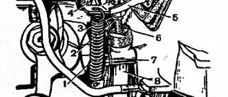
Design of a 3-shaft, 5-speed gearbox
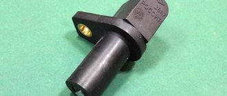
1 - input shaft; 2 — bearing cover; 3 — reverse light switch; 4 — input shaft cuff; 5 — rear bearing of the input shaft; 6 — intermediate shaft drive gear; 7 — breather; 8 — 3rd gear gear; 9 — front crankcase; 10 — 1st gear gear; 11 — reverse gear; 12 — gear shift rods; 13 — retaining ball; 14 - spring; 15 — shift lever; 16 — protective seal; 17 — lever cap; 18 — shift lever housing; 19 — rear housing; 20 - secondary shaft; 21 — rear crankcase extension cuffs; 22 — steel-babbit bushing; 23 — speedometer drive gear; 24 — speedometer drive; 25 — rear bearing of the intermediate shaft; 26 — 5th gear gear; 27 — bolts for fastening the axis of the reverse gear; 28 — reverse intermediate gear; 29 — intermediate shaft; 30 - oil filler plug.
Connected to the clutch, the input shaft through a gear transmission transmits torque to the intermediate shaft, all gears of which are rigidly fixed. The primary and secondary shafts rotate in the same axis, but independently of each other. The gears of the primary shaft are not fixed; the secondary and intermediate shafts are constantly engaged. Synchronizers that equalize the rotation speed are mounted between the gears of the secondary shaft.
The switching mechanism (rod, lever, forks) is mounted on the box body. A device is also installed that prevents the simultaneous activation of two speeds.
There are types of manual transmissions with a large number of stages (from 4 to 6), equipped with additional gearboxes called gearboxes. They can be downward (demultipliers) or upward (multipliers). The first ones with two or three speeds are mounted behind the gearbox, reducing the gear ratio by up to 3 times. The latter are mounted in front of the gearbox and double the number of gears.
Troubleshooting
If the VAZ 2109 gearbox howls, then the simplest repair is to check the level and change the oil in the crankcase. To eliminate all other defects, it is necessary to remove the box from the car and completely disassemble it. To do this, you need a closed room, a large number of various tools and experience in repairing such units.
Lack of oil
The oil level is measured using a dipstick installed in the upper part of the gearbox housing. A volume located at any distance between the minimum and maximum marks on the probe rod is considered normal. On the oldest gearboxes that do not have an overdrive fifth gear, the amount of fluid is measured through a hole in the side, closed with a plug. The level should be at the bottom edge of this hole.
Dipstick for checking the oil level on the VAZ 2109 box
To maintain the normal condition of the oil, it should be changed after 75 thousand kilometers. When filling, use API GL-4 standard lubricants with a viscosity of 75W-90, 80W-85 or 80W-90. Some owners specially fill in thick oil of the TM-5 type, which reduces the noise of the box. If replacing the lubricant does not correct the situation and the mechanism continues to make noise, then the problem lies in worn-out gearbox parts.
Replacing the drive shaft bearing
Before replacing the bearings, the gearbox must be removed from the vehicle.
To remove the gearbox you must:
The procedure for removing the box from a VAZ 2109 is shown in the video from the author of AUTO REZ.
After completing the steps described above, you need to disassemble the gearbox and remove the input shaft.
To remove and replace worn bearings, follow the steps:
Wear of gears in the box
To perform the repair, you will need to remove the gearbox from the car according to the instructions described above and completely rebuild the gearbox. In this case, the condition of all parts of the mechanism should be assessed, since not only gears, but also other mechanisms can be worn out.
The sequence for disassembling the gearbox is as follows:
The procedure for disassembling the box is described in detail on the video of the AUTO RES channel.
The drive shaft of the VAZ 2109 box has several gears, one of which is made in the body of the shaft, and the second has a high interference fit. Therefore, the input shaft gears cannot be replaced and are replaced with a completely new shaft. Maintenance of this part consists of replacing the bearings, which are removed with mounting tools or a puller. Only the secondary shaft of the box can be disassembled, and the parts should be marked or laid out in the order of removal. This method makes it easier to reassemble the unit.
Shaft disassembly sequence:
Changing the synchronizer clutch
Work on replacing couplings is carried out on a disassembled box in the same way as changing blocking rings. After removing the clutch and hub assembly, it is necessary to disassemble this unit.
The video, made by user Sem, shows how you can quickly assemble a synchronizer.
Clutch adjustment
To adjust the clutch, do the following:
Measure the clutch pedal travel Unscrew the nuts securing the cable Adjust the cable
Possible causes of VAZ 2109 gearbox failures
Like any other device, the “nine” gearbox begins to fail over time. The quality of spare parts used during repairs also plays a significant role. If you adhere to the manufacturer’s recommendations, then gearbox repairs (including preventative ones, in the absence of breakdowns) should be performed every 50,000 km. Let's consider the main causes of gearbox breakdowns according to the “symptoms” listed above:
"outgoing gear"
Most likely, the gear block of the ejected gear is badly worn. The locks on the clutch or gear may be worn and these parts will need to be replaced. The main reason is systematic violation of operating rules, incorrect choice of speed mode, too sharp switching, incorrectly adjusted clutch.
transmission noise when operating in neutral gear
Any gearbox has a certain noise threshold, which cannot be an indicator of a breakdown; not a single gearbox operates absolutely silently. An increased noise level may indicate the need to change the oil in the box or its insufficient level. In addition, noise may increase if the engine is unstable. For example, if a sports camshaft was installed on the car, and the gearbox does not resonate with it. For a more accurate diagnosis, it is recommended to take it to the nearest service station, since the gearbox can make noise for many reasons, including those not related to the gearbox itself.
the gear engages with a crunch, shifting into gear is difficult
If the gearbox has a decent mileage, then the reason is most likely the wear of the synchronizer. It urgently needs to be replaced, as the situation is fraught with failure of the entire gear unit. When the gearbox is new, or the synchronizer has recently been changed, the gears may also be a bit difficult to engage - this is normal.
The gear does not engage smoothly and requires effort to engage
Difficulties when engaging a gear can be explained, as mentioned above, by replacing the synchronizer. Over time, the parts break in and switching is effortless. Immediately after replacing the synchronizer, it is not recommended to shift gears abruptly and maintain short pauses when switching. The transmission still does not engage - use a double squeeze. If the gear does not engage clearly, this may indicate a malfunction in the gear selection mechanism, as well as incorrect adjustment of the rocker or its support. To accurately determine the cause, you need to examine the backstage.
gearbox play - shift lever dangling
First of all, check the condition of the “cardan” (gearbox joint). Very often, the cause of play is a conical fastening bolt that can unscrew. Backlash can also occur in the rocker itself as a result of its wear. In this case, it is necessary to replace the link. In addition, the return spring may burst. This part is located in the gear selection mechanism - the gearbox will need to be repaired and the spring replaced.
the curtain rings
It should be noted that this is a very common drawback of all domestic cars, very often occurring after repairs to the chassis. Sometimes it happens the other way around - after repair, the clanging disappears (if it happened on a new car). The reason may be a manufacturing defect, which even AvtoVAZ representatives admit.
In addition, the reason may be vibration of the engine + gearbox, which is transmitted to the scenes. The ringing may be associated with the car body or incorrect choice of support points. In such cases, attempts are made to eliminate the ringing by installing an o-ring near the rocker (relevant only for VAZ 2108-2115).
oil leak from box
Possible reasons are poor fastening of the crankcase cover, loss of tightness of the shaft seals. In addition, you may need to replace the box seal or simply tighten the drain plug. It also doesn’t hurt to inspect the gearbox housing for damage and cracks.
Malfunctions and their elimination
Gearbox repair largely depends on the nature and type of fault. There are several options for the breakdown of this unit, in each of which appropriate actions should be taken to eliminate them.
| Malfunction | Possible reasons | What do we have to do |
| There is noise in the gearbox |
|
|
| Gears are difficult to shift |
|
|
| Spontaneous gear disengagement occurs |
|
|
| Gears are switched on with noise and crackling |
|
|
| There is an oil leak from the gearbox |
|
|
In most cases, problems with the gearbox are eliminated by dismantling and disassembling it. Do not take on this type of work without the proper skills and experience.
Operating principle of the gearbox
The structure of any gearbox: clutch (which in an automatic transmission is called a torque converter); transmission mechanism of gears (planetary gear); gear shifting components; control system.
The principle of operation of a manual transmission is more or less clear: the driver manually changes gears, creating different combinations of gears. The drive shaft is connected to the engine crankshaft through the clutch; the connection to the driven shaft is not fixed.
The required pair of gears is selected using the forks of the control mechanism. The handle moves drives, couplings, and sliders. The gear selection mechanism is installed in the transmission, on the steering wheel or in the body.
The short video below shows the essence of a manual transmission.
A synchronizer that equalizes by rotating the shafts makes it possible to change the speed without harming the unit. To change gear, you need to press the clutch, which disconnects the gearbox from the engine. Then we turn on the desired gear (at the start - first). The pedal is released after changing speed.
How the synchronizer works:
- when the lever is in neutral, the engine does not interact with the wheels, the gears rotate freely;
- after the driver has engaged the gear, the rocker connects the lever to the gearbox, the fork moves the clutch to the desired gear through the cables;
- at the same time the crackers move the blocking ring;
- the rotation of the gear and shaft creates friction, due to which the ring rotates all the way;
- the clutch stops moving due to the fact that the ring and gear are positioned opposite each other;
- speeds are equalized, the coupling can pass through the ring to connect with the desired gear and transmit torque;
- the gear and shaft are locked, the speed is switched on.
Synchronizer device
1 - hub; 2 - sliding coupling; 3 — locking ring; 4 - spring; 5 - retaining ring; 6 — helical transmission gear; a) spur-cut additional gear ring; b) the internal working surface of the sliding coupling.
Sometimes the synchronizer turns on 2 gears at the same time. In order for the car to move in reverse, an additional shaft equipped with an intermediate gear is mounted.
Instructions for removing, disassembling and assembling the VAZ 2114 gearbox
Removing the gearbox is required when troubleshooting parts and the mechanism of the gearbox itself; when replacing the clutch.
Repair work may require one business day, so the instructions below must be started in the morning. Hiring a partner with experience in this type of repair will reduce time costs and improve the quality of repairs.
Preparation
The preparation process consists of the following steps:
- to warm up the oil to be drained, we drive a vehicle for a distance of 5 km;
- we install the vehicle on an inspection ditch (pit) or drive it onto an overpass;
- We put the car on the handbrake;
- raise the hood;
- fix the raised hood;
- we install the hoist, or use improvised means, or a special device, which is a crossbar to support the engine in a suspended position.
Removing and disassembling the gearbox. Procedure for cleaning gearbox parts
We perform the following steps sequentially:
- We remove the terminals.
- We remove the battery.
- We remove the battery to the side.
- We unscrew the three bolts that secure the crankcase protection.
- We remove the protection.
- If the model is before 2003, then remove the oil level dipstick.
- Using a 17 key, unscrew the plug (plug) of the drain hole.
- Place a five-liter container under the drain hole.
- Drain the existing oil from the gearbox into a container.
- We are waiting for the oil to be completely removed from the gearbox.
- We unscrew the two locking nuts of the starter protective jacket, located below in relation to the pit, and one locking nut on top of the starter.
- Remove the protective jacket of the engine starter.
- Disconnect the power wires to the engine starter.
- We remove the engine starter from below, that is, by descending into the pit.
- Remove the clutch cable.
- Compress the spring holding the block.
- From below, disconnect the block with the wires of the speed sensor under the hood.
- Disconnect the reverse sensor wire connector.
- We unscrew the bolts under the hood connecting the ignition module bracket to the gearbox housing.
- Disconnect the torque rod bracket.
- Loosen the gear shift rod clamps.
- We remove it by pulling the torque rod from the hinge intended for changing gears.
- We take out the gear shift rod.
- Unscrew the fastening bolts to the steering knuckle of the left ball joint.
- We carry out dismantling by disconnecting the lower mounting of the gearbox to the engine (sometimes it is enough to loosen the tightening).
- Unscrew the bots.
- Removing the transmission housing
- We unscrew the bot from the lower left part of the gearbox.
- Using a board, we hang the motor.
- We remove the fixation of the left and rear (attachment to the body) engine mount by unscrewing the corresponding nuts.
- We unscrew the pair of bots that secure the rear engine mount to the transmission, holding the nuts against spinning with a second wrench.
- We dismantle the support.
- We insert a screwdriver into the hole between the engine cylinder block and the clutch housing.
- Using an inserted screwdriver, we move the box along the guides so that the rear part of its body passes over the backlight extension, and the input shaft is disconnected from the clutch.
- We remove the gearbox unit from under the car.
- We clean the gearbox parts, removing deposits with a brush.
- We clean the holes and slots from dirt.
- We wash and blow off the parts and bearings with a stream of compressed air.
- We examine the details of the gearbox.
- If necessary, we replace worn or damaged parts.
- We carry out the assembly, focusing on the procedure indicated above.
Synchronizers with locking rings
Design of a synchronizer with locking rings
The basis of this type of mechanism is a hub with internal splines for mounting on the secondary shaft and with an external ring for installing a sliding clutch. Also on the outer surface of the part there are three grooves into which spring-loaded crackers fit with clamps in the form of semicircular protrusions or spring-loaded balls. The hub moves freely on splines along the shaft.
A sliding coupling with a longitudinal groove on the outer surface for the gearshift fork is put on the hub using splines - with the help of this fork the coupling moves along the shaft. On the inner surface of the coupling opposite the crackers there are recesses for clamps that prevent accidental movement of this part.
On both or one side of the hub there are spring-loaded bronze locking rings. The rings on the outer surface have rims with the same type and number of teeth as on the outer surface of the hub, thanks to which the coupling can slide along them. Inside the rings there is a conical surface mating with the conical surface on the corresponding transmission gear. Typically, the conical surface has a number of narrow longitudinal grooves, which, when in contact with the surface on the gear, remove the oil film from it, increasing the friction forces that arise between these parts. There are cutouts on the side surfaces of the rings opposite the crackers; their width is greater than the width of the crackers, so the rings can deviate by several degrees from the central position.
This type of synchronizer works quite simply. When the transmission is shifted into an upshift or downshift, the clutch with the fork moves forward or backward, but due to the coupling of the clutch with the clamps on the nuts, the entire synchronizer moves. Moving towards the gear, the locking ring with its conical surface comes into contact with its conical surface. Due to frictional forces, the ring, receiving torque from the rotating gear, rotates and rests on the cracks, causing the entire synchronizer and the secondary shaft to rotate. However, complete transmission of torque does not occur - due to inertial forces, the ring and coupling are displaced relative to each other, their teeth rest against each other with their ends, and the coupling is blocked. At a certain moment, the angular velocities of the gear wheel and the locking ring are equalized, the inertial forces disappear and a small force on the fork is enough to push the clutch onto the ring and then onto the gear crown. As a result, the torque from the gear is transmitted through the clutch and synchronizer hub to the secondary shaft and then to the clutch.
On the secondary shaft of a gearbox with this type of synchronizer there are gears, on one side of which there is a conical surface for contact with the locking ring and an outer ring gear of a larger diameter for connection with the sliding clutch.
Rear
As for the latter, its gear ratio is 3.53. Reverse speed ensures that the transmission shaft rotates in the opposite direction. To do this, it needs an additional shaft with a separate gear. As a result, the number of gear pairs changes to an odd number, and the torque changes its direction. Also, this transmission does not have a synchronizer - it will not be possible to turn it on at speed. The VAZ-2114 gearbox has a gear with an equal gear ratio, which is 0.941. This is fourth speed. Thus, the transmission output shaft rotates with the same force as the secondary one. That is, the angular speed of rotation of the two elements is the same. Motorists call it “straight”.
Do-it-yourself checkpoint disassembly
The box must be dismantled in an inspection hole on an overpass or on a lift. To remove and disassemble the VAZ 2109 box you will need the following tools, accessories and consumables:
• Screwdriver Set. • Rubber and metal hammers. • Impact screwdriver (required). • Chisel. • A set of socket heads with ratchets. • A wrench designed to remove circlips. • Clean rags. • Sandpaper. • Gasoline, solvent (to wash the body after dismantling). • Oil. • Gaskets.
The choice of workplace depends only on convenience and personal preferences. A good option is a wide, strong table (workbench). All manipulations can be done on a flat floor, although this is not entirely convenient. In general, all you need for the job is a clean, flat surface and good tools.
dismantling the gearbox
• First of all, drain all the oil from the box. • Unscrew the bolts securing the crankcase protection.
• Disconnect the ground wire from the clutch housing. • Loosen the nuts on the end of the drive cable. • Disconnect the block from the traction relay.
• Remove the starter.
• Disconnect the drive rod from the joint tip (speed rod). • Disconnect the speedometer cable.
• Unscrew the tie rod ball joint. • Next, press the steering rod hinge pin out of the strut arm. • We squeeze out the shank of the CV joint of the wheel drive and move it a little to the side. • Disconnect the second ball joint.
• Remove the clutch housing shield.
• Loosen the fastenings and remove the box.
disassembling the box
First, you should clean the surface of the box from dirt and oil, then wash it with solvent, gasoline or kerosene.
• Place the box vertically and carefully remove the back cover.
• Remove the clutch cable bracket, then use a rubber hammer to knock down the rear cover of the box. • Remove the old gasket. You can throw it away. • Engage 3rd and 4th gear. • Unscrew the bot that holds 5th gear and turn it on.
• Unscrew the nut first on the secondary shaft, then on the primary.
• Remove the 5th gear synchronizer with the fork.
• Remove the plug from the coupling. At the same time, we make sure that the spring-loaded balls that hold the synchronizer do not fall off. • Remove the 5th gear synchronizer locking ring. • We take out the 5th speed driven gear from the secondary shaft. • Dismantle the thrust ring of the needle bearing and take out the bearing itself. • Dismantle the drive gear of the input shaft. • From the secondary shaft we remove the bushings that remain from the needle bearing and dismantle the thrust washer. • We take out the retaining ring of the primary shaft bearing, then remove the ring from the secondary shaft. • Unscrew the locking plug, remove the ball and spring.
• Remove the rear engine mount. • Unscrew the reverse gear lock (plug), tilt the box body slightly and remove the lock ball and spring. • Loosen and completely unscrew the bolts of the clutch housing, as well as the gearbox housing.
• Disconnect the gearbox.
• Unscrew the bolt that secures 1st and 2nd gears. • Dismantle the rod and fork.
• Unscrew the bolt securing 1st and 2nd gears.
• Unhook the rod head from the lever, then remove it from the box together with the fork.
During the process of disassembling the gearbox, carefully study all the elements. If a worn part is detected in time, it can be replaced immediately, thus avoiding expensive repairs. The assembly of the VAZ 2109 gearbox is carried out strictly in the reverse order. In this case, the gasket must be replaced with a new one.
Device
To understand the essence of repairing, disassembling and assembling a gearbox, first of all you need to get acquainted with its structure. In the case of the VAZ 2109, the box structure is as follows:
- On the input shaft there is a block of drive gears that are in constant mesh with the driven gears of the gears when moving forward;
- The second shaft has driven gears with needle bearings. There is also a pair of synchronizers located there;
- The secondary shaft is created together with the drive gear of the main transmission;
- The driven gear of the main gear is attached to the flange of the two-pinion differential box;
- Differential bearings are always mounted with interference, which is adjusted by selecting rings of different thicknesses.
Checkpoint diagram
What kind of oil is poured into the VAZ 2109 gearbox, advice from the pros
When choosing oil for the “nine” you shouldn’t experiment too much; just read the car’s operating manual. You can also ask the opinion of the owners of this brand, of which there are a lot. As for the plant’s recommendations, the manufacturer recommends using all-season mineral grades:
Reksol T - SAE 80W-85 class Gl-4. Omskoil Trans P. Volnez TM4 - SAE 80W-90 class GL-4.
The manufacturing plant almost always fills boxes with Lukoil mineral oil. It is quite enough for the first time. However, it is not very suitable for use in winter, so after purchase it is recommended to replace the oil with any of the ones listed above.
Replacing a component such as oil
For the VAZ 2109 car to function properly, its systems and components must be coated with oil. In the case of the VAZ 2109 car, the manufacturer does not indicate the exact characteristics of such an element as oil, so you can use both engine and transmission oil. The following recommendations can be given here: if the VAZ 2109 car mainly drives around a big city, then preference should be given to this type of motor oil, and if the car is driven on the highway, then gear oil is quite suitable. Also, when pouring oil into the box of a VAZ 2109, you need to pour a little more oil than it should be, you shouldn’t skimp. This approach will allow covering all parts of the system, even those located at the exit from the crankcase.
The principle of operation of the synchronizer
All actions of the gearbox synchronizer occur in a fraction of a second. When the gearshift lever is in neutral, the gears and clutches do not transmit power and rotate freely. If you want to increase the speed by shifting the gearbox, the lever positions the clutch in the direction of the gear. In this case, the following happens in the system.
When the required gear is engaged, the nuts (small gates) move on the clutch, acting on the locking ring, which collides with the gear cone. This activates a frictional force that turns the ring until it locks, at which point the speed of the gear and shaft are synchronized. As a result of this, the engine is adjusted to a different speed, and the driver can increase speed without much effort.
Removal and installation of gearbox VAZ 2114, VAZ 2115, VAZ 2113, Lada Samara 2
Removing the gearbox.
Place the vehicle on a lift or inspection ditch. Raise the engine hood and lock it in this position. Removal work carried out from inside the engine compartment of the Lada Samara 2:
– disconnect the wires from the battery, from the starter traction relay; – disconnect the ground wire from the clutch housing; – disconnect the lower part of the VAZ 2113 clutch cable as described in subsection. "Clutch"; – unscrew the two upper bolts securing the clutch housing to the engine block and the two upper nuts securing the starter, attach a bracket for lifting the power unit to the left stud of the engine exhaust manifold;
Installing a cross member to support the power unit: 1 – cross member 67.7820.9514
– install cross member 67.7820.9514 on the drain gutters to support the engine and hook it onto the bracket installed on the exhaust manifold stud. If there is no cross member, hang the power unit with a hoist. Removal work carried out from below the car: – remove the engine mudguard and the lower cover of the clutch housing; – drain the oil from the VAZ 2114 gearbox; – disconnect the wires from the reverse light switch;
Mounting the gearbox on the car: 1 – engine; 2 – bracket for fastening the power unit; 3 – suspension arm extension bracket; 4 – stretching; 5 – gearbox; 6 – wheel drive shaft; 7 – suspension arm; 8 – anti-roll bar; 9 – rear support of the power unit; 10 – clamp; 11 – gear shift lever drive rod; 12 – internal hinge housing
– loosen clamp 10 (Fig. 3.11) and disconnect rod 11 from the hinge of the gear selection rod of Lada Samara 2; – unscrew the nut of the stud securing the gearbox to the VAZ 2115 engine; – disconnect the ball joints of the suspension arms from the steering knuckles; – using a puller 67.7801.9524 or sharply hitting the body 12 of the internal joint with a hammer through a drift, knock out one hinge from the side gear, then fix the side gear with a technological mandrel or plug used when transporting the differential (otherwise the unfixed side gear may fall into the gearbox housing) ; then knock out the second hinge; – move the wheel drive shafts to the sides;
NOTE If it is difficult to separate the wheel drive from the side gear on the car, remove the gearbox assembly with the wheel drive and on a workbench, using the same puller, press the hinge out of the side gear.
– unscrew on the left side the three nuts of the studs securing the gearbox to bracket 2 of the power unit suspension, and then the nut from the bolt securing the bracket itself. Having removed the bracket from the gearbox studs, remove the suspension bracket 2 from the body spar eyelets; – unscrew the bolts securing the rear support 9 of the power unit suspension; – unscrew the lower nut securing the starter and remove it; – install a special stand with a hydraulic lift under the gearbox; – slightly lower the engine by extending the support rod of the cross member or lowering the hoist, unscrew the lower bolt securing the crankcase to the engine block and move the gearbox assembly with the clutch housing away from the engine to separate the gearbox shaft and the driven clutch disc; – remove the VAZ 2113 gearbox.
Basic faults
The clutch is an essential part of a car using a manual transmission.
In addition to knowledge about the operation of the clutch, it is important to have an understanding of malfunctions
The most common of them:
- The clutch does not disengage completely. Air entering the release drive creates the feeling of a sinking pedal, as a result of which the driver cannot completely disengage the clutch;
- the clutch does not engage. Common cause: cable break;
- The clutch pedal refuses to return to its original position. Cause: the return spring has failed or is disconnected;
- loud noise when disengaging the clutch. The noise indicates wear of the release bearing;
- The clutch is not fully engaged. There are many reasons: wear of the drive disk linings, faulty springs, small pedal travel.