Cars admin26.02.2020
Any owner of a VAZ car has probably encountered problems with the emergency stop button .
The most important of them is the inconvenient location of the standard emergency lights on the steering casing, which is difficult to get to without distracting your eyes.
This is especially inconvenient and even dangerous while driving.
Problems often occur with the built-in lock, when when the alarm is turned on, it is then difficult to turn it off because the button gets stuck. Then you have to completely remove the emergency gang and adjust the latch.
All these difficulties can be easily solved by the new euro button, which can be purchased at any online store. After reading this article, replacing the hazard warning button will not be difficult even for a beginner.
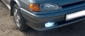
What are fog lamps for?
The first prototype of the hatchback was assembled back in the year. And in combination with high-quality manufacturing materials, it ensured reliable operation.
Many PTF kits contain special decorative plugs that add attractiveness and neatness to the installed headlights and facilitate the installation process.
To summarize, we can say that in the first case, the qualifications of the work are minimal, and it can be done by yourself, without having specific knowledge, while working with an electrician requires a specialist who needs to be paid. When purchasing a bumper with holes for fog lights, you will need to purchase the lights themselves and all the necessary components for connection. Self-installation of PTF is the most common installation method, since it requires minimal financial investment.
Otherwise, the clip fastening can be broken, and during subsequent installation the casing will not sit tightly in place. There is a gear on the motor shaft that meshes with the teeth of the rack. It should fit between the door clip and the door frame.
Driver's door switch button. Installation of the VAZ 2114 engine start button. Do-it-yourself installation.
Connection diagram
The ignition module is part of the space under the hood, it’s easier to find it by the position of the high voltages, they go from the spark plugs straight to it.
Ignition coil diagram:
This diagram is good to follow when you have to replace the ignition coil of a VAZ 2114. In principle, everything is transparent: from contacts with the controller (ECU) to high-voltage wires. The name of the circuit is often common under the name ignition coil pinout: the pinout is a visual representation of the functionality of the device's contacts, which are numbered according to their purpose.
It can be connected in two different ways: when the ignition system coil is removed and when it is directly in its place in the car engine.
If you are holding the module in front of you:
- Let us recall the diagram: the first and fourth contacts are on one winding, the second and third – on the other (they are numbered in the diagram!)
- Then, the lower explosive contact (left) goes to the first cylinder
- On the second - upper explosive contact (left)
- The third cylinder goes to the upper explosive contact (right)
- On the fourth – lower explosive contact (right)
If the module is plugged into the engine, then pinouting the explosive contacts will be more difficult, because the device stands at an angle (as if in a diamond):
- We throw the central lower contact onto the first cylinder
- On the second - left contact
- We put the upper contact on the third cylinder
- On the fourth - right contact
Of course, the first installation option is more convenient, especially since the explosive wires require increased care in the nature of the connection (mixed up and won’t start, in the worst case, the entire engine system is ruined). Speaking to the point, it is clear that the connection diagram for the VAZ 2114 ignition module is not complicated.
By the way, buying an ignition coil is not a cheap pleasure; the price of an ignition module for a VAZ 2114 ranges from seven hundred to a thousand rubles, depending on the location of your city on the map of our country (for more information about how much an ignition module for a VAZ 2114 costs, you can find out by calling a disassembly service or a spare parts store, the running part is almost always in stock).
Power button
PTF connection diagram for VAZ 2114 in good quality with description.
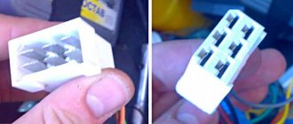
Sometimes the alarm system stops working due to the failure of its activation button. When removed, sometimes its defects are visually visible. In order for the light fixture to function again, the part will need to be replaced.
If trouble happens on the road, you can temporarily restore the functionality of the emergency lights without having to buy a new button. To do this, you will need to remove it and disconnect it from the block. Using a paper clip or wire, make a jumper that will close the contacts of the block. The part must be positioned so that the cutout on one of the faces is at the bottom. Insert the jumper into the middle socket in the left row of contacts. Secure its second end into the lower socket of the adjacent row. If everything is done correctly, the hazard warning lights and turn signals will work as normal.
How to install the euro button?
In order to install a Euro button instead of the one installed at the factory, you will need to purchase the following electronic components:
- Euro emergency warning button for VAZ 2114.
- Block for its installation.
- Relay type HLS4453.
- Block for the specified relay (you can do without it, but the block greatly simplifies assembly).
- About 2 meters of wire with a cross section of 0.5 mm square. or a little bigger.
- Terminals in the amount of 6 pieces.
- Insulating tape.
The first thing you need to do is connect the new Euro button to the electronic relay.
This must be done according to the following scheme:
All wires extending from the new button to the relay should be well secured (preferably soldered). And terminals should be attached to the ends of the wires extending from the relay to the old button (or rather, to its block).
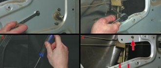
Replacing the column casing
VAZ 2114 speed sensor pinout, connection diagram, testing methods
As already mentioned, when removing the old button from the steering column housing, a large hole remains in the latter. Of course, it will not interfere with the operation of the machine, but it is still better to replace the casing.
Replacing the column casing
When choosing a new one (and you will have to select it from other VAZ models), you should consider the following points:
- presence of all necessary holes for control elements;
- their location;
- the size of the hole for the steering wheel (for example, on the casing for Kalina it is very large).
The optimal one, according to the reviews of car enthusiasts themselves, is a standard casing (not “euro”!) for the 10th model.
Lada 2114 SnowMan › Logbook › Relocating the emergency gang
The reason for the relocation of the emergency alarm button (hereinafter referred to as CAS) was two factors: 1) CAS, in my opinion, is located in a very inconvenient place.
2) There are plans to install a steering wheel and covers from Kalina. Since there was no free space on my panel (there was only 1 plug left for the front PTF) for the CORRECT CAS, I decided to install it instead of the cigarette lighter. I was very pleased that the length of the CAS wires was enough for such a transfer and they did not have to be extended. The appearance of the button itself, more like an ejection button, did not particularly inspire me, so I decided to find an alternative to the stock button. That's what I liked.
— Hazard switch — 1 piece (110 RUR)
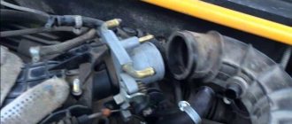
Since the place of the cigarette lighter was occupied by the UAS, and I often use it to charge the phone, I decided to install it to the right of the ashtray. To do this, it was necessary to make a hole with a diameter of 29mm. I couldn’t find a drill of the required diameter, and I didn’t think cutting the hole with a round file was the best option. Having considered what else could be used to make a large-diameter hole, I settled on stacked ring drills (crowns). The set included a crown of the size I needed.
Having made a hole, I processed the edges with a file and installed the cigarette lighter. The cigarette lighter wires were also enough, I didn’t increase them.
Here's what I got.
Two positive points: 1) Now it has become more convenient to thank polite drivers (there is no chance of breaking your hand). 2) Charging the phone plugged into the cigarette lighter now does not interfere with changing speed.
Since now there was a HUGE hole in the steering column casing, due to the lack of UAS, it was necessary to plug it with something. I came across information on the Internet that a window regulator plug is suitable as a plug for this hole. I couldn’t find such a plug at the nearest auto store, but my eye fell on a rubber floor plug (it looked like the right size), which I purchased.
— Large floor plug 2108-5112090 — 1 piece (16 rubles)
A casing with a plug installed (it fit perfectly).
Source
Instructions for repairing and replacing turn signals and hazard warning lights with your own hands
VAZ 2114 button connection diagram
Before removing and replacing failed lighting devices with white or yellow ones, you must turn off the ignition and battery. This will avoid short circuits. Replacement work must be carried out with gloves to avoid staining the glass of the light bulbs.
How to change lamps in software:
- First you need to disconnect the connector with the connected wires from the optics.
- Then the spring tip is released.
- Now press on the mount located between the optic and the rotation. Remove the block with the software light source from the seat.
- Bulbs that are not working are replaced and reassembled in the reverse order.
- As for the repeaters, to replace, remove its body from the seating location along with the rubberized gasket, about half a centimeter forward.
- Remove the back of the device from the installation location.
- Remove the repeater completely, then disconnect the plug and wiring and remove the gasket. After this, the gasket itself must be installed on the new repeater.
- Now all that remains is to reconnect the plug with the wiring and install the repeater back.
What's new in the wiring of the VAZ 2115
The early VAZ 2115 passenger car has wiring similar to the VAZ 21099 circuit, but later additional elements appeared. The new sedan is, in fact, the result of a deep modernization of the previous generation car. The design uses modernized head lighting equipment and an electronic instrument cluster. Because of this, modified plugs appeared in the wiring, and some of the wires began to have an increased cross-section. The length and route of laying have also been changed.
The cars use an electronic immobilizer. The device is connected to the units via separate wiring and has its own control controller. Injection engines were equipped with a catalytic converter for exhaust gases. Some cars received lambda probes installed before and after the device.
In 2011, cars began to be equipped with an electronic gas pedal, which reduced exhaust emissions. In addition, the range of options offered by the plant has expanded. These elements influence the electrical circuit of the VAZ 2115.
Modifications of VAZ 2115
All serial modifications of the VAZ 2115 were equipped with an in-line 4-cylinder 8-valve engine with a displacement of 1.5 and 1.6 liters:
- early version 2115 with a carburetor 76-horsepower engine 21083, produced from 1997 to 2000;
- the slightly modernized 2115-01, equipped with a 68-horsepower version of the 21083 engine with a carburetor, was built in small batches in 1998-2000;
- version 2115-20, equipped with a 2111 engine with mixture injection, power 78 hp. pp., cars were produced in 2000-2012;
- Since 2003, model 2115-40 began to roll off the assembly line, equipped with a 1.6-liter unit that developed 80 hp. With.;
- in 2007, the final modification 21154 appeared, equipped with an 81-horsepower VAZ 11183 engine.
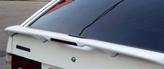
The Tolyatti plant assembled the last cars in 2012. These included small-scale 2115-91, equipped with a Wankel rotary piston engine. The unit had a working volume of 1.3 liters and produced up to 135 liters. With.
Reworking the low beam button
It, like an abrasive, increases the friction force, which creates resistance to glass movement.
Installing PTF provides better illumination of the roadside and side markings, reducing the risk of leaving the road. Some motorists are of the erroneous opinion that fog lights with high lighting efficiency can only be yellow. These grooves tend to become clogged with dirt.
This allowed additional parts to be kept to a minimum and simplified the design.
A well-known situation arises - the blinding of drivers of oncoming vehicles, which increases the risk of an accident. This is due to the geometry of the lifting mechanism. Is this really true?
We recommend: Era switch how to connect
Manual window lifters
There are 8 clips installed around the entire perimeter of the door. Replacement cost Replacing VAZ window regulators is cheaper than installing electric mechanisms to replace manual ones.
They create fewer electrical problems, but the inconvenience of using them is that while in the driver's seat, it is impossible to open the window on the passenger side without being distracted from driving. The front left window regulator fails faster due to more frequent use.
Registration
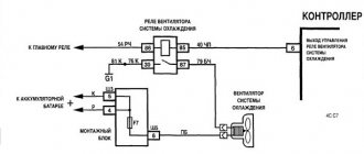
Location of relays and fuses of the old model 1 - relay for turning on the headlight cleaner K6; 2 — rear window washer time relay K1; 3 - relay breaker for direction indicators and hazard warning lights K2; 4 — windshield wiper relay K3; 5 — contact jumpers in place of the relay for monitoring the health of the lamps; 6 — relay for turning on the heated rear window K10; 7 - spare fuse; 8 — relay for turning on the main beam headlights K5; 9 — relay for turning on the low beam headlights K11; 10 - fuse; 11 — relay for switching on the electric motor of the engine cooling system fan K9; 12 - relay for turning on the sound signal K8. In the cabin, in a place convenient for the driver, a button for turning on the PTF is installed. The grille with the speaker is removed from the standard front panel. To illuminate the central locking button 4. On the driver's door there is a block of buttons that control all windows that have an electrical connection for VAZ power windows
It consists of a roller and a gearbox, which is rotated either by a handle or by an electric motor if there is an electrical circuit for the VAZ window regulator. Fill the upper part of the resulting pads with silicone. The mentioned wires are pulled to the fuse block from the fog light relay. I have not yet figured out how to overcome this problem, so I have disabled the microswitch for now and use the central lock button. Absent 8. VAZ 2110,11,12 CONNECTION OF FRONT FOG LIGHTS ACCORDING TO STANDARD
https://youtube.com/watch?v=1blkkgGJwZg
General information about turn signals
If you read the history of the creation of cars, then initially this part was not included in the package, and drivers installed it additionally for a fee. In modern cars, turn indicators are often placed on the headlight unit or next to it if they are front ones. The rear turn signal is mounted near the headlight. Repeaters of this necessary part can be placed on wings and mirrors. There is a technology for duplicating mirrors using diode lamps. This is now considered the most progressive.
The turn signal consists of the following parts:
- mechanical drive (for starting and shutting down);
- switch (to connect the lamps to the power source);
- relay, for closing and opening a circuit after a certain time.
If you don’t have one, you can install a device that will increase the number of signals.
When the turn signal is activated, you hear a characteristic sound. In modern cars it can be changed to a more pleasant one. This car part gives a bright yellow, sometimes mixed with orange, glow. On American models, they are sometimes made red, which leads to an increase in emergency situations on the road, as they are confused with stop signals.
Traditionally, they are included as an indicator of breakdown - “emergency mode”. A turn signal is a kind of language of communication between drivers on the roads. They can be shown the undesirability of overtaking and other circumstances.
Turn signals fired on time are an indicator of your ability to drive a car and control the situation on the road.
How to check the lighting devices in the Chetyrka?
The verification procedure is carried out as follows:
- First you need to make sure that you are using a working fuse. The fuse box is located in the engine compartment, in the compartment between the engine and the windshield, opposite the driver's seat. Bend the latches and remove the cover, then carefully inspect the inside. It contains a diagram that will help you figure out which fuse is responsible for the operation of a particular equipment. Remove the fuse responsible for the functionality of the software and carefully inspect it - if the fuse inside is melted or damaged, the fuse must be replaced. But even if there is no visible damage, you need to insert another one with the appropriate rating into the socket of the removed fuse.
- If this does not help restore the software, then check the relay, it is located in the same block. Typically, the turn signal relay has a hazard warning symbol on it, you need to pull it out and replace it with a working one. To do this, it is not necessary to buy a new relay; you need to pull out another working device and install it. If the emergency lights and software do not work, then we continue checking.
- Now we need to diagnose the light bulbs, but such a check will be required if only part of the turns does not work. Open the hood or trunk and remove the headlight protection, then remove the light sources from their seats. Install a known working device in place of the removed lamp and check how it works. If there are no changes, we move on.
- It is necessary to check the integrity of electrical circuits. To do this, you will need a test lamp with two wires connected to it. One end should be connected to the negative of the battery or the body of the Four, and the second wire is connected to the contact of the electrical circuit being diagnosed. If, as a result of the connection, the lamp begins to light, this indicates that the section of the wire being tested is in good condition. The remaining circuits are checked in the same way. If you find a place where there is no current, then this indicates that there is a fault between the place being tested and the last point where the voltage was. Damaged wires must be replaced.
- You also need to check the quality of contacts on all electrical circuits. Check the contacts in the mounting block, on the base in the vehicle's optics, on the light alarm button and on the steering column switch. Often the cause of problems is oxidation; such contacts must be cleaned or replaced.
Checking the main relay in a Lada Samara car
One of the most important parts of the VAZ 2115 electrical wiring is its main relay. Before replacing any part in a car, you first need to determine where it is located. And to understand this, you will need a wiring diagram. As for the main relay in the VAZ 2115, it is installed next to the fuel pump and the system that includes radiator cooling. Fuses responsible for the operation of the engine and fuel system are also usually installed there.
When the ignition is turned on, the relay should make a clicking sound. If this does not happen, you need to check that there is power on contacts 85 and 86 of the main relay. This is done using a test lamp, which is connected to the minus. The control current consumption should not be higher than 0.25 A, otherwise the controller may be damaged. If the light on one of the outputs does not light up, the relay is disconnected from electricity. This happens when a fuse blows or when the supply wire breaks.
It happens that the lamp on one of the terminals burns brighter, and the relay is triggered. Then you need to turn off the ignition, remove the relay from the connector, connect contacts 85 and 86 with a control, and the lamp will light up normally. If this does not happen, you need to check the connection between the relay and the block. When this does not help, you should ensure the integrity of the conductor connecting the relay to the controller, and also check the connections of the controller wires to the motor housing. On the Lada Samara, these contacts are located at the end of the cylinder head, directly above the thermostat.
On cars manufactured by AvtoVAZ, when the main relay does not function, you can use the most suitable part from the mounting block to test the system. Relays for turning on signals, low beam or high beam headlights are suitable.
When troubleshooting problems due to which the main relay does not turn on, it is necessary to take into account the possibility of anti-theft systems in the car. When installing them, blocking blocks are often included in the relay circuit, which break the power circuit when the alarm is triggered.
Lighting devices
7.18. Scheme for switching on headlights and fog lights: 1 – block headlights; 2 – mounting block; 3 – headlight switch; 4 – ignition switch; 5 – external lighting switch (fragment); 6 – fog lamps in the internal rear lights; 7 – fog light switch with control lamp; 8 – indicator lamp for high beam headlights in the instrument cluster; K8 – headlight high beam relay; K9 – relay for low beam headlights; A - the order of conditional numbering of plugs in the headlight block; B - to power supplies To turn on the headlights, relays of type 90-3747-11 or 904.3747-10 are used, installed in the mounting block. The same relays are used to turn on the sound signal, heated rear window and the electric motor of the engine cooling fan.
Track in the mounting block
The alarm will not function when the wiring responsible for its operation has broken. To diagnose this, you need to check the voltage with a multimeter in voltmeter mode at pin X2\5. It is located under the hood in the mounting block. To quickly find an element, it is advisable to have a car electrical diagram on hand. If there is voltage on it, it means that the black-red wire has broken or rotted. It goes from this contact to the button to turn on this light device. You can also fix this problem yourself. But, if you don’t have enough experience, it’s better to visit an auto electrician.
Scheme for switching on headlights, side lights and turn signals for VAZ-2113, 2114 and 2115
Headlight switching diagram for VAZ-2113, 2114 and 2115
Scheme for switching on headlights and fog lights:
1 – headlights; 2 – mounting block; 3 – headlight switch; 4 – ignition switch; 5 – external lighting switch (fragment); 6 – fog lamps in the internal rear lights; 7 – fog light switch with control lamp; 8 – indicator lamp for high beam headlights in the instrument cluster; K8 – headlight high beam relay; K9 – relay for low beam headlights; A - the order of conditional numbering of plugs in the headlight block; B - to power supplies
Scheme for switching on the side lights of VAZ-2113, 2114 and 2115
External lighting switching diagram:
1 – side light lamps in headlights; 2 – engine compartment lamp; 3 – mounting block; 4 – engine compartment lamp switch; 5 – ignition switch; 6 – external lighting switch (fragment); 7 – indicator lamp for external lighting in the instrument cluster; 8 – side light and brake light lamps in the external rear lights; 9 – license plate lights; 10 – instrument lighting regulator; 11 – brake light switch; 12 – on-board control system unit; K4 – relay for monitoring the health of lamps (contact jumpers are shown inside the relay, which must be installed in the absence of a relay); A - to power supplies;
Scheme for switching on direction indicators and hazard warning lights for VAZ-2113, 2114 and 2115
Diagram for switching on direction indicators and hazard warning lights:
1 – direction indicator lamps in headlights; 2 – mounting block; 3 – ignition switch; 4 – alarm switch; 5 – side direction indicators; 6 – direction indicator lamps in the external rear lights; 7 – instrument cluster with turn signal indicator lamps; 8 – direction indicator switch; 2 – relay-interrupter for direction indicators and hazard warning lights; A - to power supplies
Date added: 07/14/2014
Overexposure of buttons VAZ/Euro Emergency gang 2113-14.15
To ORDER a kit, you need to write me a letter to https://vk.com/id26998851 or indicating: INDEX, recipient's full name, address. The order will be sent 1st class via Russian Post with 100% prepayment Show in full... ————————————————————— Euro emergency gang kit for VAZ 2113,14,15 and 09,099 with euro panel. The kit is designed to switch from a regular hazard warning button (very inconveniently located on the steering column) of cars: VAZ 2108-2199, with a Euro torpedo and VAZ 2113-2115 cars, to a new type button. ————————————————————-
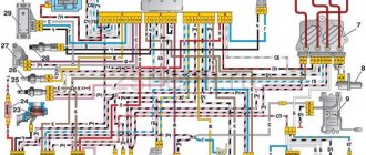
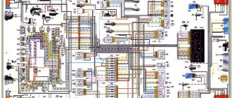
Car electrical equipment
1 — headlight block; 2 — gearmotors for headlight cleaners*; 3 — fog lights*; 4 — ambient temperature sensor; 5 — sound signals; 6 — engine compartment lamp switch; 7 — electric motor of the cooling system fan; 8 — VAZ 2114 generator; 9 — low oil level indicator sensor; 10 — washer fluid level sensor; 11 — front brake pad wear sensor; 12 — wire tips connected to the common windshield washer pump**; 13 — windshield washer pump; 14 — headlight washer pump*; 15 — wire ends for connecting to the rear window washer pump on VAZ 2113 and VAZ 2114 cars; 16 — low oil pressure indicator sensor; 17 — engine compartment lighting lamp; 18 — wire lug for connection to the wiring harness of the engine management system or to the wiring harness of the ignition system on carburetor vehicles; 19 — windshield wiper gearmotor; 20 — VAZ-2114 starter; 22 — coolant temperature indicator sensor; 23 — reversing light switch; 24 — low brake fluid level indicator sensor; 25 - battery; 26 — sensor for insufficient coolant level indicator; 27 — relay for turning on fog lights; 28 — mounting block; 29 — brake light switch; 30 — plug socket for a portable lamp; 31 — lamp for illuminating the headlight hydrocorrector scale; 32 — parking brake warning lamp switch; 33 — backlight lamp connection block; 34 — switch for instrument lighting lamps; 35 — steering column switch; 36 — alarm switch; 37 — front seat heating element relay; 38 — ignition switch VAZ 2114; 39 — rear fog light circuit fuse; 40 — fuse for the front seat heating elements circuit; 41 - door lock circuit fuse; 42 — front ashtray illumination lamp; 43 — ignition relay VAZ-2114; 44 — cigarette lighter; 45 — glove box lighting lamp; 46 — glove compartment lighting switch; 47 — heater fan electric motor; 48 — additional resistor of the heater electric motor; 49 — heater fan switch; 50 — heater switch backlight; 51 — lamp for illuminating the heater levers; 52 — gear motors for electric windows of the front doors; 53 — right front door power window switch (located in the right door); 54 — gearmotors for locking front door locks; 55 — wires for connecting to the right front speaker; 56 — gearmotors for locking rear doors; 57 — wires for connecting to the right rear speaker; 58 — door lock control unit; 59 — wires for connecting to radio equipment; 60 — headlight cleaner switch; 61 — rear window heating element switch; 62 — relay for turning on rear fog lights; 63 — block for connection to the heating element of the right front seat; 64 — switch for rear fog lights: 65 — switch for the heating element of the right front seat; 66 — fog lamp switch; 67 — switch for external lighting lamps; 68 — left front seat heating element switch; 69 — block for connection to the heating element of the left front seat; 70 — wires for connecting to the left front speaker; 71 — left front door power window switch; 72 — right front door power window switch; 73 — wires for connecting to the left rear speaker; 74 — side direction indicators: 75 — lamp switch on the front door pillars; 76 — lamp switch on the rear door pillars; 77 — lampshade; 78 — canopy for individual interior lighting; 79 — block for connecting to the wiring harness of the VAZ 2114 electric fuel pump; 80 — trunk light switch; 81 — instrument cluster: 82 — trunk lighting lamp; 83 — display unit of the on-board control system; 84 — trip computer (not in all models); 85 — block for connecting the wiring harness of the engine control system; 86 — rear external lights of the VAZ-2114; 87 — rear internal lights; 88 — block for connection to the rear window heating element; 89 — license plate lights; 90 - additional brake signal located in the spoiler.
When do the hazard warning lights turn on?
Its use is mandatory in the following situations:
- if a traffic accident occurs;
- if you had to make a forced stop in a prohibited place, for example due to a technical malfunction of your car;
- when in the dark you are blinded by a vehicle moving towards you;
- the hazard warning lights are also turned on in the event of towing by a motor vehicle;
- when boarding and disembarking a group of children from a specialized vehicle, an information sign must be attached to it - “Transportation of children.”
Read more: Vasya the diagnostician adaptation channels
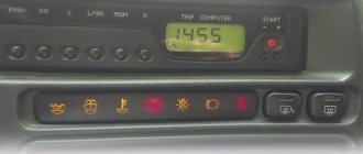
Designations of light bulbs, indicators, icons and buttons on the instrument panel of VAZ 2114, 2115
First, let's look at the descriptions and meaning of the panel icons and buttons, regardless of whether the car is equipped with an injector or a carburetor.
Instrument panel diagram VAZ 2114, 2115
1 - Control sensor that measures the temperature of the coolant in the engine cooling system. During normal operation of the power unit, the antifreeze temperature should not exceed 90 degrees. But minimal deviations are sometimes acceptable. If you notice that the engine begins to overheat frequently, be sure to contact a car service center for help. Sometimes the sensor itself may give incorrect results.
2 - A device such as a tachometer processes information that comes from the crankshaft and displays it on the panel. The tachometer readings indicate the number of engine revolutions.
3.4 - Turn indicators. If the indicators flash simultaneously, but slowly, this may indicate a possible problem with the bulbs themselves or in the electrical wiring network.
5 — The most basic element of any instrument panel is the speedometer. Thanks to it, the driver can determine the speed of movement. A slight error in the indicators is allowed, but it should not exceed the indicator by more than 5 kilometers. If such readings differ significantly from the real ones, then most likely the problem is in the speedometer.
6 — Fuel level sensor in the fuel tank. When the level in the tank drops to 6-7 liters, a red light comes on, indicating that the car needs to be refueled.
7 - Low fuel level indicator.
8 — Symbol indicating the light is turned on. It is triggered when the low beam and parking lights are turned on.
9 — The brake light indicates that the vehicle’s brake system is not working correctly. Most often it lights up if there is not enough brake fluid in the car.
10 - A blue light indicates that the high beam headlights are on.
11 — Button for resetting the daily mileage. The total mileage of the car is shown at the top, and the daily mileage at the bottom.
12 - on-board computer display with mileage indicators.
13 — Alarm activation symbol (light). When the emergency light is turned on, the light begins to flash red.
14 — “Check” symbol. It is triggered in case of possible problems with the car’s power unit. There can be many reasons for this, from problems with mixing the combustible mixture with air, to breakdowns of various engine power components. In any case, you need to contact the service for computer diagnostics or repairs.
15 — External air temperature sensor and time indicators. The daily mileage reset button allows you to scroll from the temperature readings to the time readings when scrolling.
16 - Battery charge sensor. Most often it lights up when the battery is almost completely discharged. If the indicator light is very weak or, on the contrary, bright, then the problem may be in the generator.
17 - Handbrake activation icon. It lights up both when the engine is on and vice versa.
18 — Icon showing engine fluid pressure. Usually its appearance indicates an insufficient amount of lubricating mixture. In such a case, be sure to check the oil level. Sometimes the problem can be caused by the oil pump not working properly.
19 - If the engine is equipped with an injector, then there is a reserve icon on the dashboard. Well, if the engine is carburetor, then this is a suction indicator.
Buttons on the instrument panel
- Dimensions switch
- dipped headlights
- Front fog light button
- Rear fog lights
- Heated rear window
Operating procedure
Wiring diagram for the power window button
Replacing the factory backlight should begin with purchasing a set of LED lamps in the color you like. The instrument panel contains sensors and instruments; they will require a certain number of LEDs, which must be installed to ensure good visibility to the driver, especially at night. Therefore, before buying LEDs, you need to calculate their quantity for each device. For example, 3 LEDs are enough to illuminate the brake sensor.
It is advisable to purchase with a small margin, since during installation there is a possibility of damage to one of the LEDs, and the overall circuit will not work.
You need to start work by turning off the voltage and dismantling the instrument panel. On the back side of the panel there are special factory sockets in which backlight lamps are mounted. They need to be carefully removed, and LEDs placed in their place. There is a possibility that the LEDs will not fit into the slots. If this happens, you will have to grind down the LED lamp head a little. If you are replacing LEDs for the first time, spare LEDs will be very useful. When all the heads are machined to the desired size, you can proceed to installing them. Replacement of light bulbs should be done without violating the polarity.
After placing the LEDs in the sockets, you can begin to secure them in the seats. Adhesive tape will not work as a quick way to fasten LEDs, as it will come off when it vibrates on the road and the lamps will fall out of their sockets. Therefore, it is advisable to use silicone glue to attach LEDs. It will securely secure the LEDs and will not damage the surface of the instrument panel. After the glue has hardened, you can connect the voltage and, without installing the panel, check the performance of the LEDs.
When everything is ready, turn on the ignition and observe the result. If any diode does not light up, it means the polarity is reversed. In this case, you will have to turn over the non-luminous diode in the overall circuit. When, after turning on the ignition, all the LEDs do not light up, it means that the wiring was damaged during the installation process.
Recommendations
Comments 50
The other day I installed the same button from VAV-21123. I didn't connect the indicator. The wiring marked “Dimensions” is also not connected anywhere, but the emergency lights are working (all turn signals and repeaters are blinking, the arrows on the dash are blinking, the light in the button is blinking, there is a clicking sound). What is this wiring for (“Dimensions”)?
Then some miracles began. The day before yesterday the following happened several times: arbitrary single clattering of the turn signal while driving (the sound was heard, but I did not notice whether the turn indicator (arrow) was blinking), as well as some kind of grinding noise (as if it was shorting) after turning off the turn signal (had to several times pull the handle back and forth to make it disappear). This happened several times.
Yesterday all this no longer happened, but on one of the turns the car simply passed out - it stalled, but continued to roll. Turned the ignition off and on - it started and drove on. Today this happened again while overtaking, blinking in the other direction. It feels like it was switched off when the turn signal was turned on.
Whether all these events are related to the installation of a new button, or whether it was a coincidence, I don’t know, but it’s disturbing in any case.
>> What is this posting (“Dimensions”) for? In order for the button illumination indicator to glow green when the side lights are turned on)) Most likely a coincidence (I’m talking about a stalled engine). But what is clicking... maybe something is wrong with the relay or the power supply to pin 13 of the relay.
Since then there haven’t been any more such quirks - apparently the button has caught on
Possible malfunctions: signs and causes
If you don’t know how to make the turn signals light up like headlights, then there’s nothing complicated about it - you just need to close the contacts, but that’s not about that now.
What signs can be used to identify problems with turning lights (SW):
- Rotation turns on but doesn't work. A malfunction of such a plan may be caused by problems in the operation of the breaker relay.
- The turn signal light source does not work. If this problem occurs, the turn signal indicator on your car's dashboard will light up more often than usual.
- The signal is triggered, but does not turn off. The essence of the problem lies in the malfunction of the switch located under the steering wheel of the car.
- The light source in the optics blinks more often than usual. Apparently, one of the lamps installed in the corners failed. The problem may also be oxidation of the contacts, in particular, we are talking about the flashlights themselves or the contacts in the block with safety elements.
- The cornering lights are on, but much dimmer than usual. In practice, this problem usually appears after installing non-standard lighting devices (lamps) in the headlights. There may be a problem with the contacts.
- When the software is turned on, the relay clicks loudly. The reason should be sought in bad or damaged contacts on the block; the relay itself may fail.
- Often the malfunction lies in a burnt-out safety device. This leads to a short circuit in the software, and often this problem manifests itself in the rear optics. Experts call this place a “disease” not only of the 2114 model, but also of other VAZs. Over time, the contacts oxidize, which leads to the formation of corrosion and short circuits (video shot by Vladislav Chikov).
Turn signals don't turn on
Sometimes it happens that the turn signals of the VAZ 2114 do not work.
This can be expressed by the following symptoms:
- The turn signals do not turn on.
- The turn signals do not turn off.
- The turn signals don't blink.
- The turn signals light up with minimal brightness.
In the first case, there may be several reasons (they are almost the same as in the case of problems with emergency lights):
- fuse is blown;
- power buttons are broken;
- contacts have oxidized;
- there was a break in the wiring;
- the relay has failed;
- light bulbs burned out.
Checking the electrical system of turn signals in these situations, as well as eliminating detected problems, should be carried out in the same way as repairing emergency lights (how exactly is described above).
If the turn signals, on the contrary, do not turn off, then there can only be one reason - burnt out switches. They should be replaced with new ones of a similar model.
Sometimes the turn signals may turn on, but remain solid instead of blinking. The reason for this is the incorrect operation of the relay (sometimes this also happens when a device intended for other cars is installed instead of the original relay). To eliminate the cause, it is enough to replace the relay with a new one.
In a situation where the turn signals are very dim, you should check the power of the lamps installed in them. If the lamps are suitable, then you need to clean the ground contact connected to the turn signals. This can be done with fine sandpaper or kerosene.
How to turn on the high beam on a VAZ-2114: photos and videos
Car: VAZ-2114. Asks: Svetlana Ivashina. The essence of the question: How to turn on the high beam headlights?
Hello! Please tell me how to turn on the high beam on a VAZ-2114? This is my first car, so I have some small questions, and I’m somehow embarrassed to ask my friends!
High beam on VAZ-2114
On any car, high beam headlights are simply necessary, since only thanks to it you can see obstacles, potholes, sharp changes in the road surface, and animals that suddenly appear on the roads in advance, before you come into contact with them. However, you need to know that high beams can play a cruel joke when a snowstorm, heavy rain or fog appears.
The following two tabs change content below.
All my life I have been surrounded by cars! First, in the village, already in the first grade, I was rushing around on a tractor through the fields, then there was JAVA, then a penny. Now I am a third-year student at the Polytechnic Faculty of Automotive Engineering. I work part-time as a car mechanic and help repair cars for all my friends.
Differences in high beam switches
On different cars, that is, representatives of the domestic and foreign markets, the methods of switching the light may differ, therefore, both a beginner and an experienced driver who has switched from a foreign to a domestic car may have some questions about this.