05/08/2020 480 Electrical wiring and electrical circuits
Author:Ivan
The ability to read and understand the electrical diagram of a VAZ 2115 allows you to determine the cause of a malfunction that occurred on the road, as well as independently install additional equipment. It should be taken into account that cars of different years of production differed in the electrical system and instruments.
[Hide]
Car modifications 2115
VAZ-2115 . The very first car that was produced since 1997. It was equipped with a 1.5-liter carburetor engine producing 76 horsepower. The maximum speed was 165 km/h, and the acceleration time from 0 to 100 km/h was 13.2 seconds.
VAZ-21150 . The next modification, released in 1998, was equipped with a 1.5-liter carburetor engine producing 68 horsepower. was discontinued in 2000.
VAZ-2115-20 . A modification of the car released in 2000, equipped with a 1.5-liter VAZ-2111 injection engine with a power of 77.8 horsepower. The maximum speed was 170 km/h, and the acceleration time from 0 to 100 km/h was 14 seconds.
VAZ-2115-40 . A modification with a 1.6-liter injection engine, which has been produced since 2003. The car's maximum speed was 158 km/h, and the acceleration time to 100 km/h took 13.2 seconds.
VAZ-2115-91 . A car with a 1.3-liter Wankel rotary piston engine producing 135 horsepower. The maximum speed is 190 km/h, and the acceleration time to 100 km/h is 9 seconds.
VAZ-21154 . The latest modification of the car with a new VAZ-11183 engine with a volume of 1596 cm3 and a power of 81 horsepower. Produced since 2007. The maximum speed and acceleration time to 100 km/h are exactly the same as that of the VAZ-2115-40.
Pressure
First of all, you will need to measure the pressure in the fuel supply system. If the pump works as it should, it is about seven atmospheres. To check, the pressure gauge is connected to the ramp through the fitting there. Remove the cap from it and screw on the measuring device.
If everything is in order, then the readings will be as follows:
- 2.5 kPa (idle);
- 3 (ignition on);
- 7 (if you pinch the fuel outflow hose);
- 2.5-3 (increase in speed).
In the same situation, if after the ignition is triggered the pressure gauge does not show anything, then most likely the pressure regulator has failed.
When no changes occur even after gaining speed, then the issue here is clearly in the fuel pump. A slow change in readings indicates a clogged filter mesh.
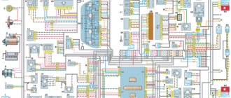
Electrical diagram of VAZ-2115-01
Years of production 2115: 1997—2012. This is a circuit with a regular button for rear fog lights (with locking), a fluorescent interior light, a connector for the clock and an 8-pin connector for the injector wiring.
1 — block headlights; 2 — fog lights; 3 — air temperature sensor; 4 - generator; 5 — electric motor of the engine cooling system fan; 6 — fan motor activation sensor; 7 — engine compartment lamp switch; 8 — block for connection to a single-wire type audio signal; 9 — sound signal; 10 — oil level sensor; 11 — front brake pad wear sensors; 12 — washer fluid level sensor; 13 — spark plugs; 14 — ignition distributor sensor; 15 - switch; 16 — carburetor solenoid valve control unit; 17 — carburetor solenoid valve; 18 — carburetor limit switch; 19 — speed sensor; 20 - starter; 21 - battery; 22 — relay for turning on fog lights; 23 — coolant level sensor; 24 — brake fluid level sensor; 25 — reverse light switch; 26 — coolant temperature indicator sensor; 27 — engine compartment lamp; 28 — windshield wiper gearmotor; 29 — oil pressure warning lamp sensor; 30 — block for connecting to the rear window washer electric motor; 31 — electric motor for windshield washer; 32 — ignition coil; 33 — instrument cluster; 34 — mounting block; 35 — brake light switch; 36 — blocks connected to the injection system wiring harness; 37 — ignition switch unloading relay; 38 — ignition switch; 39 — glove box lighting lamp; 40 — switch for the glove compartment lighting lamp; 41 — rear window heating switch; 42 — fog light switch; 43 — fog light switch; 44 — external lighting switch; 45 — alarm switch; 46 — steering column switch; 47 — instrument lighting regulator; 48 — hydraulic corrector scale illumination lamp; 49 — socket for a portable lamp; 50 — side direction indicators; 51 — switches in the front door pillars; 52 — lamp for individual interior lighting; 53 — electric heater fan; 54 — additional resistor of the electric heater fan; 55 — heater electric fan switch; 56 — backlight lamp for the electric heater fan switch; 57 — backlight lamp for heater control levers; 58 — display unit of the on-board control system; 59 — trip computer; 60 — switches in the rear door pillars; 61 — block for connection to the clock; 62 — electric fuel pump with fuel level sensor; 63 — ashtray lighting lamp; 64 — cigarette lighter; 65 — trunk lighting; 66 — trunk light switch; 67 — interior lamp; 68 — parking brake warning lamp switch; 69 — external rear lights; 70 — internal rear lights; 71 — plugs for connecting to the rear window heating element; 72 — license plate lights; 73 - additional brake signal.
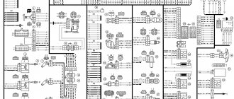
See the complete diagram in one file below (click to enlarge):
There is a harness for the carburetor ignition system with a speed sensor; it is not connected to the injector. The 4th wire of the interior lamp is the ignition, so that when the ignition is turned on, the backlight goes out immediately. Jumper on Ш11 for wipers. On 2109 they are powered through a fuse on the motor (6-pin), here it is not used and therefore there are 5 wires going to the motor.
Circuit 2115 with “high” panel 21083 is similar to circuit 21099 (except for the rear harness).
The fuel pump relay does not turn on.
If the fuel pump does not work, then first of all you need to check the attraction of the main relay and the fuel pump relay. If the main relay does not click, then it is necessary to check its switching circuit and its serviceability. How to do this is described in the article the main relay does not turn on,
In the case when the main relay turns on, but the fuel pump relay does not, it is necessary to check the power at pins 85 and 86. When using a test lamp, its current consumption should not exceed 0.25A, otherwise damage to the controller may occur. If the control lamp does not light up on any terminal, then the relay is not receiving power. This may be caused by a blown fuse or a broken power cord.
In the case when the lamp burns brightly on one terminal, and at half-glow on the second, and the relay may be activated, you should remove the relay from the socket and connect terminals 85 and 86 with a test lamp. When the ignition is turned on, the control lamp should light up and go out after approximately 20 - 30 seconds. If the lamp lights up and there is poor contact in the connection between the block and the fuel pump relay. If the lamp does not light up, there may be a break in the wire connecting the relay to the controller or the controller itself may be faulty.
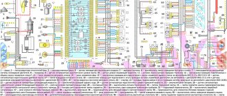
Scheme of VAZ-2115 Lux configuration
The luxury package is a model with headlight cleaners, heated seats, electric windows, central locking, a trip computer and a fluorescent interior lighting.
- block headlights;
- gearmotors for headlight cleaners*;
- fog lights*;
- ambient temperature sensor;
- sound signals;
- engine compartment light switch;
- engine cooling fan electric motor;
- generator VAZ-2115;
- low oil level indicator sensor;
- washer fluid level sensor;
- front brake pad wear sensor;
- wire ends connected to the common windshield washer pump**;
- windshield washer pump;
- headlight washer pump*;
- wire ends for connecting to the rear window washer pump on VAZ-2113 and VAZ-2114 cars;
- low oil pressure indicator sensor;
- engine compartment lamp;
- wire lug for connecting to the engine management system wiring harness;
- windshield wiper gear motor;
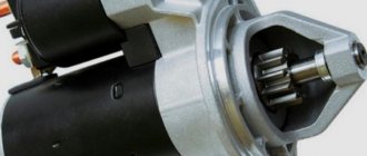
- starter VAZ-2115;
- block connected to the wiring harness of the ignition system on carburetor cars;
- coolant temperature indicator sensor;
- reverse light switch;
- low brake fluid level indicator sensor;
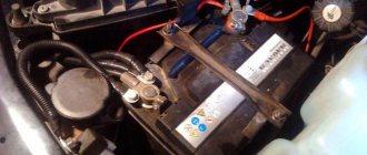
- accumulator battery;
- low coolant level indicator sensor;
- relay for turning on fog lights;
- mounting block;
- brake light switch;
- plug socket for a portable lamp;
- hydrocorrector scale illumination lamp;
- parking brake indicator lamp switch;
- block for connecting a backlight lamp;
- switch for instrument lighting lamps;
- Understeering's shifter;
- hazard switch;
- front seat heating element relay;
- ignition switch;
- rear fog lamp circuit fuse;
- front seat heating elements circuit fuse;
- door lock circuit fuse;
- front ashtray illumination lamp;
- ignition relay;
- cigarette lighter VAZ-2115;
- glove box lighting lamp;
- glove compartment light switch;
- heater fan motor;
- additional heater motor resistor;
- heater fan switch;
- heater switch illumination lamp;
- heater lever illumination lamp;
- gear motors for electric windows of the front doors;
- right front door ESP switch (located in the right door);
- gear motors for locking front door locks;
- wires for connecting to the right front speaker;
- gear motors for locking rear doors;
- wires for connecting to the right rear speaker;
- door lock control unit;
- wires for connecting to radio equipment;
- headlight wiper switch*;
- rear window heating element switch;
- rear fog light relay;
- block for connection to the heating element of the right front seat;
- rear fog light switch;
- right front seat heating element switch;
- fog light switch*;
- switch for external lighting lamps;
- left front seat heating element switch;
- block for connection to the heating element of the left front seat;
- wires for connecting to the left front speaker;
- left front door power window switch (located in the left door);
- right front door power window switch (located in the left door);
- wires for connecting to the left rear speaker;
- side direction indicators;
- dome light switches on the front door pillars;
- dome light switches on the rear door pillars;
- lampshade VAZ 2115;
- individual interior lighting lamp;
- block for connecting to the wiring harness of the electric fuel pump;
- trunk light switch;
- instrument cluster;
- trunk light;
- on-board control system display unit;
- trip computer*;
- block for connecting the wiring harness of the engine management system;
- rear exterior lights;
- rear interior lights;
- pads for connecting to the rear window heating element;
- license plate lights;
- additional brake signal located on the spoiler.
Useful: Pinout of diagnostic connector for VAZ cars
Numbering order of plugs in blocks:
A - headlight units and headlight cleaners; B - cigarette lighter; B - mounting block, instrument cluster, ignition switch, windshield wiper and other electrical components (for blocks with a different number of plugs, the numbering order is similar); G — relay for turning on the rear fog light; D — alarm switch; E — electric window motors and door lock motors; F — interior lamp.
In the instrument panel wiring harness, the second ends of the white wires are brought together into one point, which is connected to the instrument lighting switch (except for the white wire, from plug “4” of block “X2” of mounting block 28 to display block 83 of the on-board control system). The second ends of the black wires are also brought together to points connected to ground. The second ends of the yellow wires with a blue stripe are brought together to a point connected to plug “4” of the “X1” block of the mounting block. The second ends of the white wires with a red stripe are brought together to a point connected to plug “10” of the “X4” block of the mounting block. The second ends of the orange wires are brought together to a point connected to plug “3” of the “X4” block of the mounting block.
Explanations for the 8-pin injector block: white-red and blue - for the check light bulb, blue-red - ignition, gray - speed sensor, brown-red - tachometer, blue-white - driver's door switch (for the immobilizer), green- red - K-line (may not exist), green - fuel consumption. Next to it is a pink wire - to the fuel level sensor.
See the complete diagram in one file below (click to enlarge):
The fuel pump does not work, the relay turns on.
Checking relay power.
In the case when the fuel pump relay turns on when the ignition is turned on, but the pump itself does not work, you need to check the power at terminal 87 of the fuel pump relay. To do this, touch terminal 87 of the relay socket with the output of the control lamp connected to the vehicle ground, and the lamp should light up. If the lamp does not light, it means the fuse has blown or there is a break in the wire.
If there is power at terminal 87, you should remove the relay from the socket, and instead place a jumper between pins 87 and 30. In this case, if the pump and connecting wires are working properly, the pump should start working and if this happens, the relay should be changed. If the pump does not start working, then, without removing the jumper, you need to touch the power wire on the fuel pump with a test lamp connected to the vehicle ground.
Checking the fuel pump power circuit.
If a submersible pump is installed on the car as part of the fuel module, you need to remove the connecting connector and touch one of the thick wires. When you touch one of them, the indicator lamp should light up. If the lamp does not light up on any of the wires, then it is necessary to eliminate the break in the wire from the fuel pump relay to the module connector or the pump itself, if the pump is of a remote type. One of the reasons for the break may be the anti-theft blocking of an installed non-standard alarm system.
In the case when the test lamp lights up on one of the thick wires of the connector or one of the terminals of the remote pump, you need to connect these terminals with a test lamp to each other. In this case, the control lamp should light up. If the lamp does not light, it is necessary to eliminate a break or poor contact in the wire connecting the pump to the vehicle ground.
If, when checking the wires and relay for turning on the fuel pump, no malfunction is detected, the electric motor of the fuel pump or its connection to the module connector is faulty. It is not difficult to find the cause by removing the fuel pump module from the tank. If there is poor contact with the connector, melting of the plugs will be visible. If melting is not noticed, then to check the pump itself, you can connect it to the battery. It should be taken into account that operating a submersible pump without liquid will damage the pump. A faulty pump should be replaced.
VAZ-2115 wiring harness diagrams
With a 9-pin square block for the injector, a non-locking button for turning on the automatic transmission, and a starter blocking relay (the injector turns off the starter if the engine is running).
Instrument panel harness
There is a relay for rear fog lights (attached next to the mounting block, the fuse dangles nearby), a button without locking. It works like this: if the low beam and/or front fog lights (if equipped) are on, press and release the button - the automatic transmissions turn on. They turn off when the button is pressed again or automatically when the headlights are turned off, so that the driver does not forget to turn them off.
Glove compartment lighting harness
There is a magnet on the lid; when it is far from the sensor with the reed switch, the glove compartment light turns on (the reed switch closes the contacts).
Front harness with fog lights
Rear harness VAZ-2115
License plate light harness
Wiper harness 2115
Additional harness - lock
Connects to the instrument panel, the connector is next to the hood handle. Pink - door lock, permanent plus, fuse hangs next to the hood release handle. White and black - on the door for electric windows, plus during ignition, switched on through a relay and fuse in the mounting block. Also in the photo is the wiring for the radio speakers.
Right door harness
Connects to an additional harness.
Left door harness
Connects to an additional harness.
Seat heating harness
The gray wire is connected to the connector where the additional harness is connected (to the gray wire if there is one), plus when igniting, the relay is attached next to the mounting block and the fuse is located next to the hood handle. The white wire is connected to the additional harness, button illumination.
How to check the performance of the fuel pump
Often, for those problems for which the car owner blames the fuel pump, other elements of the fuel system are to blame. To establish whether a fuel pump has failed, you will need to know the reasons why it might break.
Causes of fuel pump malfunctions
Most often, the device may fail while the vehicle is moving. The gas pump may simply refuse to pump fuel from the tank to the engine, or a leak may form, causing the device to malfunction. If the power supply is interrupted, the pump stops working completely.
The main causes of fuel pump malfunctions include the following:
lack of tightness in the pump itself (leakage);
damage to membrane surfaces;
the resource of the pump motor has been used up;
wiring or relay problems;
dirt and debris in the fuel tank, which, along with gasoline, enter the pump.
As you can see, there can be many reasons for a fuel pump to fail.
Dirt deposits on the filter mesh are a common cause of fuel pump malfunctions.
Symptoms of a problem
There are only four main signs by which you can diagnose malfunctions in the fuel pump without special tools:
The car simply won't start. Of course, the engine may not function for a number of other reasons, however, first of all, you will need to check the functionality of the fuel pump itself.
After the car starts, the characteristic buzzing of the fuel pump is inaudible. The whirring noise should be clearly audible in the rear of the cabin, as the fuel pump is located under the rear seats.
Recently, interruptions in the operation of the power unit have begun to be observed: the engine does not start the first time, while driving you can hear the engine straining.
The car starts to jerk when driving at low speed.
Differences from its predecessor
The VAZ 2115 car is a more modernized version of model 21099. The improvement of the “ninety-nine” contributed to the updating of the electrical wiring diagram.
It should be noted that, unlike 21099, the VAZ 2115 injector is equipped with newer body parts, in particular, we are talking about:
- improved shape of the front wings;
- the appearance of the headlights;
- back panel shape;
- different shape of the hood and luggage compartment.
Toy models VAZ 21099 and VAZ 2115
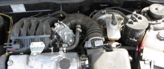
Of course, the changes also affected the engine compartment. Compared to 21099, the VAZ 2115 is equipped with a more powerful engine. Changes also affected the interior - a more advanced center console, instrument panel, and seats. An on-board computer was also added to the design of the car. Accordingly, the overall dimensions of the VAZ 2115 also underwent changes. But in general, this car remained the same - a front-wheel drive, five-door and five-seater sedan.
Diagnostics
A malfunction of the VAZ 2114/2115 fuel pump can be caused by:
- malfunctions in the device’s power supply circuit;
- failure of starting and protection elements (relay and fuse);
- wear of electric motor parts.
Checking the electrical circuit
At the beginning of the diagnosis, you should check the electrical circuit of the fuel pump. To do this you will need:
- car tester (multimeter);
- crosshead screwdriver;
- two pieces of wire about 2 m long.
Checking the electrical circuit is carried out in the following order:
- Turn on the ignition without starting the engine. When the key is in the first position, a click should be heard, characteristic of turning on the relay, followed by a slight whirring of the pump electric motor. If there is no click, the relay is faulty or is not receiving power. If there is a click, but no buzzing, the wiring coming from the relay or the pump motor itself is faulty.
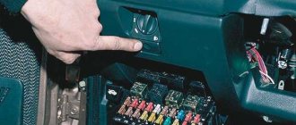
- Under the glove compartment, find an additional mounting block consisting of three relays and three fuses. The pump relay is located in the middle, and the fuse is located to the left of it. Remove the fuse from its socket, test it with a multimeter, and if the result is negative, replace it. When replacing the fuse, please note that it is rated for a maximum of 15 A.
The relay and fuse for the fuel pump on the VAZ 2114/2115 are located in the mounting block under the glove compartment.
Set your multimeter to voltmeter mode. Connect one probe of the device to the relay terminal to which the pink wire fits, and the second to the car body. Turn on the ignition. The device should show the on-board network voltage in the range of 11.7–12.4 V. If there is no voltage, the problem may be a broken wiring or a malfunction of the ignition contact group. In this case, it is better to contact an auto electrician. If power is supplied, check that the relay is working. With the ignition on, use a screwdriver or a piece of wire to close the contacts to which the pink and gray wires go. This closes the circuit bypassing the relay. If the fuel pump works, replace the relay.
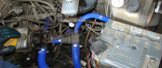
The ground wires of the fuel pump are attached to the body with a self-tapping screw
Pressure check
If the pump is working properly, but the engine begins to operate intermittently, you should check the fuel pressure in the system. For this you will need:
- pressure gauge (can be a tire gauge with a measurement limit of 5–7 kPa);
- petrol-resistant hose with a diameter of 10–12 mm and a length of 50–80 cm;
- two clamps for a hose of the appropriate diameter;
- Phillips screwdriver;
- nipple cap;
- dry rag.
In addition, the presence of an assistant is desirable.
The verification procedure is as follows:
- In the engine compartment on the engine fuel rail, locate the pressure measuring fitting (on the right side).
- Remove the plastic cap (plug) from the fitting.
Find the pressure fitting and remove the cap from it
When unscrewing the spool valve, fuel may spray out of the fitting.
Connect the pressure gauge to the fitting using a hose and clamps
Modifications
The VAZ 2115 manufacturer offers consumers a choice of several configurations, on which their cost depends:
- One and a half liter carburetor engine. In this case, the car is marked as VAZ 2115-01.
- An engine with the same volume, characterized by the presence of a distributor fuel injection system. In addition, the car is also equipped with electronic control and is labeled as VAZ 2115-20.
Dimensions of the “fifteenth” Lada
Car electrical equipment
VAZ 2115 injectors or carburetors use a single-wire electrical circuit. In this case, the negative terminal of the power supplies is connected to the minus, and the positive terminal itself is supplied with a separate wire.
As a result of the fact that the VAZ 2115 carburetor and injector have certain differences, there is also a difference in the design features of the wiring:
- In injection versions, the wiring harnesses are slightly larger in size as a result of the fact that the system is equipped with additional regulators and other electrical equipment.
- As a result of the change in the circuit, changes were made to the design of some electrical circuits.
- In addition, the layout of some of the electrical components as a whole was changed.
Wiring diagram on the “fifteenth” Lada
On VAZ 2115 cars, as on its predecessors, the process of repairing the electrical wiring diagram and equipment usually leads to damage to the fixing clips. In any case, if these elements are damaged, they must be replaced, otherwise the electrical wiring may be very close to the hot motor, which will damage it.
Machine electrical protection
The electrical circuit, in particular, the power circuits in these car models are protected from various damages using fuses. The cost of these elements in stores is minimal, but they play a very important role and must always be in working order.
Fuses do not protect only:
- car battery charging diagram;
- ignition circuit;
- electrical circuit for powering the generator and starter.
Electrical equipment is protected by a block in which all fuses are collected, and this block is located in the engine compartment. Electrical equipment such as a starter, windshield wipers, as well as optics are connected to the general circuit via a relay. The relay is also installed in the block. In general, the electrical circuit of the wiper motor and optics is protected by bimetallic reusable elements.
Injector relay block
So, how is electrical equipment protected on domestic cars:
- fuses on the block, which are designed to protect various elements of equipment, are marked as F1-F20;
- K1 is a device that protects the optical cleaner circuit;
- K2 - is responsible for the functionality of the light alarm, as well as turn signals;
- K3 - the element ensures the functionality of the windshield wipers;
- K4 - the device protects the electrical circuit of optics, in particular, incandescent light bulbs;
- K5 - if the car is equipped with electric window regulators, then this relay is responsible for their performance;
- K6 - car steering horn;
- K7 — rear window heating system device;
- K8 - long-range vehicle lighting;
- K9 - low-beam vehicle lighting.
It should be noted that the lamps for the fog lights in the rear headlights are protected separately. For this purpose, a fuse is used, installed in the vehicle interior under the center console. It is located in the wiring harness, next to the optics power button.
Electrical wiring system maintenance
To ensure the functionality of the electrical system, it is necessary to regularly check and diagnose the components:
- If problems are detected in operation (even minimal malfunctions), the condition of the connecting plugs should be analyzed.
- Often, after the owner moves the pad, contact is restored. Further use of such elements is not recommended.
- The unit needs to be replaced with a similar one, while simultaneously finding out the cause of oxidation of the old parts.
Relay contacts are prone to burning when exposed to high current. The devices can be removed from the unit and the condition of the conductive contacts can be inspected.
This requires:
- Remove the plastic protective cover.
- Carefully clean the burnt contacts with fine sandpaper and blow with air.
If there is significant wear on parts, it is necessary to install new relays.
Due to the location of the installation box in the air supply channel, it becomes clogged with dust and is exposed to moisture. Over time, this leads to the destruction of the conductive paths on the printed circuit boards and loss of contact. The unit should be inspected once a year; if defects are found, it is recommended to replace it with a new one. At the same time, it is necessary to monitor the condition of the grounding wire, which can oxidize at the connection points.
For correct operation of consumers, it is necessary to check the condition of voltage sources. The battery should be periodically recharged from a stationary device. Charging the battery and the functioning of the electrical circuit while driving depends on the tension and condition of the generator rotor drive belt. When the commutator and brushes wear out, the operation of the generator is disrupted, which leads to the car losing power.