1 – ignition coils 2 – injectors 3 – controller 4 – main relay 5 – fuse connected to the main relay 6 – cooling system electric fan relay 7 – fuse connected to the cooling system electric fan relay 8 – electric fuel pump relay 9 – fuse connected to electric fuel pump relay 10 – mass flow and air temperature sensor 11 – throttle position sensor 12 – coolant temperature sensor 13 – canister purge solenoid valve 14 – oxygen sensor 15 – knock sensor 16 – crankshaft position sensor 17 – idle speed control 18 – immobilizer control unit 19 – immobilizer status indicator 20 – phase sensor 21 – vehicle speed sensor 22 – electric fuel pump module with fuel level sensor 23 – oil pressure warning lamp sensor 24 – coolant temperature indicator sensor
A – block connected to the wiring harness of the ABS cabin group B – diagnostic block C – block connected to the air conditioner wiring harness D – to the “+” terminal of the battery D – to the side door wiring harness block E – block connected to the panel wiring harness devices
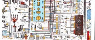
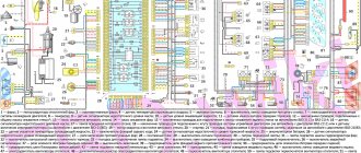
Electrical system diagram of VAZ 21124 in the engine compartment
- electric fan (No. 3);
- electric fan switch relay (No. 22);
- coolant temperature sensor (No. 7);
- electric fuel pump with fuel level sensor (No. 30);
- fuel pump activation relay (No. 21);
- electric heater of the fuel system inlet pipe (No. 4);
- power relay and heater protection fuse (No. 23 and 24);
- air temperature sensor and absolute pressure sensor (No. 5 and 6);
- engine control controller (No. 13);
- SUD fuse box (No. 20);
- fuse box (No. 27);
- ignition relay 21124 (No. 26);
- spark plugs (No. 28);
- car starter relay (No. 25);
- battery (No. 18).
Front side of the engine
The front side of the engine is located near the right mudguard. It has a two-piece plastic cover.
Below it are the drives of the gas distribution mechanism and the electric generator. The timing belt includes: camshaft gears, a coolant pump and 2 rollers, one of which regulates the tension of the timing belt. At the end of the crankshaft there is a timing gear, a generator pulley and an oil pump. These components are driven by its rotation.
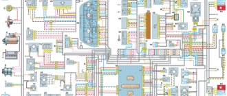
Electrical diagram of the VAZ-21104 ECM with controller 21124-1411020-30/31/32
1 — block of the ignition coil wiring harness to the ignition system harness; 2 — block of the ignition system harness to the ignition coil wiring harness; 3 — ignition coils; 4 — immobilizer warning sensor; 5 — immobilizer control unit; 6 — spark plugs; 7 — nozzles; 8 — diagnostic block; 9 — block of the ignition system harness to the ABS cabin group harness; 10 - controller; 11 — electric fuel pump; 12 — block of the ignition system harness to the fuel level sensor harness; 13 — block of the fuel level sensor harness to the ignition system harness; 14 — block of the ignition system harness to the injector harness; 15 — injector harness block to the ignition system harness; 16 — block of the ignition system harness to the side door harness; 17 — speed sensor; 18 — idle speed regulator; 19 — throttle position sensor; 20 — coolant temperature sensor; 21 — mass air flow sensor; 22 — oil pressure warning lamp sensor; 23 - phase sensor; 24 — oxygen sensor; 25 — crankshaft position sensor; 26 — knock sensor; 27 — solenoid valve for purge of the adsorber; 28 — oil level sensor; 29 — coolant temperature indicator sensor; 30 — block of the ignition system harness to the instrument panel harness; 31 — block of the instrument panel harness to the ignition system harness; 32 — ignition relay; 33 - ignition relay fuse; 34 — fuse for the electric fuel pump power supply circuit; 35 — electric fuel pump relay; 36 — electric fan relay; 37 — controller power supply fuse; 38 — ignition system harness block to the air conditioner connector; 39 — instrument cluster; 40 — ignition switch; 41 — electric fan of the cooling system; 42 — on-board control system unit; 43 — starter relay; 44 — contacts of the 8-terminal blocks of the instrument panel harness and the front harness; 45 — contacts of the 21-terminal blocks of the instrument panel harness and the rear harness; 46 — trip computer; 47 - diagnostic connector.
Historical reference
The car was equipped with a fuel injection distribution system that complies with the requirements of exhaust gas toxicity standards:
- The 16-valve power unit was equipped with an electronic system based on the M7.9.7 controller and complied with EURO 3;
- The 8-valve power unit complied with EURO 2 standards.
For reference: for brevity, the engine control system with distributed fuel injection is referred to in the diagrams as an abbreviation - SUD. For the EURO 3 engine it is equipped with a solenoid valve for purge the adsorber - in the diagram under No. 13.
EURO 3 – 16 valve version
The presented diagram shows the main components and sensors, thanks to which the control system organized the supply of the air-fuel mixture to the cylinders:
- The main components are the ignition coil, fuel injectors, controller and main relay (indicated in the diagram as numbers 1,2,3 and 4);
- A larger group of sensors includes several systems at once: power supply, cooling, air supply, engine operation, etc.
Control systems for monitoring the operation of the power unit include:
- throttle position sensor (No. 12);
- knock sensor (No. 18);
- diagnostic oxygen sensor (No. 16);
- crankshaft position sensor (No. 19);
- coolant temperature sensor (No. 13);
- immobilizer control unit (No. 20);
- coolant temperature indicator sensor (No. 26).
Visual surveillance systems include:
- immobilizer status indicator (No. 21);
- vehicle speed sensor (No. 23);
- oil pressure warning lamp sensor (No. 25);
- fuel level sensor (No. 24).
In addition, the VAZ 21124 wiring diagram also contains built-in protection elements:
- Main relay fuse (No. 5);
- Relay and fuse for electric cooling fan (No. 6 and 7);
- Fuel pump relay and fuse (No. 8 and 9);
For reference: G1, G2 indicated in the diagram are grounding points, A – ABS system block, B – diagnostic connector.
EURO 2 compliant power unit
The electronic content of the car is similar to the 16-valve version:
- single controller for power units M7.9.7
- general factory instructions for cars with different power units.
In addition to the different markings of the sensors, the car circuits are identical with the exception of the solenoid valve for purge the adsorber, which is equipped with EURO 3 engines.
Car fuses - number, current and description
F1 5 Lighting lamps: numbers, instruments, dimensions on the dashboard, left dimensions, trunk lighting F2 7.5 Low beam in the left headlight F3 10 High beam in the left headlight F4 10 Right front fog lamp F5 30 Door windows F6 15 Portable lamp, cigarette lighter F7 20 Radiator fan, horn F8 20 Heated rear window F9 20 Windshield washer and cleaner F10 20 Reserve F11 5 Clearance on the right side F12 7.5 Low beam in the right headlight F13 10 High beam in the right headlight F14 10 Fog lamp, left F15 20 Heated seats 21124 F16 10 Hazard signal, turn signals F17 7.5 Brake light, ignition switch illumination, interior lighting F18 25 Cigarette lighter, glove compartment light, interior heater F19 10 Reversing lamp, brake light monitoring F20 7.5 Rear fog lights headlights
CAR ELECTRONICS REPAIR
Starter repair
If possible, the starter is repaired.
To do this, the removed device is disassembled. Here's how to do it according to the instructions: Be sure to carefully inspect the contacts and brushes. To see the condition of the brush assembly, you need to unscrew the two screws of the back cover. After this, it will fall out into your hand - the length of the brushes must be at least 8 mm, otherwise you will have to replace them. There should be no signs of burnout or rust on the assembly. Elements should not dangle, wires should be intact.
The gears deserve special attention. They must be removed without losing the gasket. Then it’s the turn of the overrunning clutch and solenoid. First you need to unscrew the screw secured to the side of the starter housing. This will make it possible to pull the bendix off the shaft, moving the sleeve to the right. Next, remove the retaining ring. You can pry it off with a thin screwdriver, loosen it and pull it out.
Particular attention should be paid to the ring gear. It happens that it relaxes, and then you need to solder it, wash it until it shines, fill it with lithol and put it back in place.
Now you need to carefully clean all the internal components with carb cleaner, gasoline, and pure kerosene. Lubricate all rotating components and gears, as well as bushings and the traction relay mechanism with lithol. Clean the collector with fine sandpaper.
Source
General information
The car and electricity are fused together from the very beginning. You may recall that the very first such vehicle used an electric motor, until the internal combustion engine was invented.
Wiring a VAZ 2112 makes it possible to perform actions that simply cannot be carried out without electricity.
Among them are:
- ignition of the fuel mixture in the cylinders of a carburetor and injection engine;
- starting the engine;
- operation of head lighting devices at night to illuminate the road surface;
- fog lights when driving in conditions of limited visibility;
- light indication of the instrument scale;
- side lights for vehicle detection at night;
- turn indicators;
- signaling devices.
Schematic diagram of the electrical wiring of a VAZ 2112 car (16 valve)
In addition, the wiring diagram of the VAZ 2112 will help you figure out how and what the auxiliary equipment is connected to:
- “wipers”, which allow the driver to feel normal in rainy or snowy weather;
- sound signals in case of an emergency;
- searching for a spark in case of engine failure;
- CD player and radio;
- window lifters;
- windshield and rear window heaters;
- interior lighting lamps.
The electrical wiring of the VAZ 2112 connects electrical appliances and devices with current sources located in the car. An electrical equipment system is a collection of current consumers and its producers .
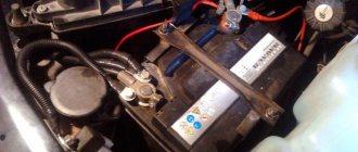
Serviced battery
Car power supplies and ignition
Let's take a closer look at it, starting with the most important elements:
A rechargeable battery is a chemical source of energy, which is a lead-acid DC battery module. The photo shows a battery being serviced. Usually there are six of them.
It is used for:
- starting the engine with an electric starter;
- supplying power to electrical equipment when the engine is not running or when it is running at low crankshaft speeds.
Generator . Used as the main source of current for all electronic and electrical devices and instruments in the car. But, it can provide this only at medium or high crankshaft speeds. The price of this equipment depends on the manufacturer.
Ignition system . Designed to ignite fuel in engine cylinders. Can be contact or non-contact. Modern VAZ 2112 cars are equipped with the latter version, which has a number of advantages over the contact system, which is already considered obsolete.
The main advantages should be noted:
- increased voltage potential supplied to the secondary winding of the ignition coil;
- increased power and longer spark discharge duration;
- increased service life of the spark plug;
- the breaker contacts practically do not fail;
- fuel burns better in the cylinders, which saves money as a result;
- makes engine starting easier;
- the engine becomes more responsive and more economical.
Starter relay installation diagram
If the battery is not charging
When the battery is no longer charged, it does not allow the car to be used for a long time. Maximum until it is completely discharged. In this case, a red light comes on on the instrument panel, which signals that the wiring on the VAZ 2112 requires checking.
The instructions below will help with this:
- Check the generator drive belt, it should be intact and have the required tension.
Advice: it is not recommended to apply too much tension; it will significantly shorten the life of the belt.
- If everything is fine, check the fuse. The VAZ 2112 wiring diagram for 8 or 16 valves, as well as the reverse side of the mounting block cover, will help you find out where it is located. After replacing it and starting the engine, the lamp should go out, allowing you to continue your journey.
Checking and replacing the fuse
- When the charging lamp does not go out, check the wire from the generator to the “+” terminal of the battery. There are usually two of them:
- thick – from the battery to the starter,
- thin - to the generator.
It should not be broken or have oxidized contacts . It happens that there is no way to fix the breakdown, which means that the generator itself needs to be repaired. Repairs must not be delayed as a short circuit may occur. But it’s better to do this at a service station or at home in the garage with your own hands.
Advice: when driving only on battery power, to reduce on-board electricity consumption, turn off as many devices as possible - radio, heater fan, etc.
AUTOFIZIK.RU / auto repair
On the eight-valve VAZ-21114 engine, unlike the VAZ-2111 engine, phased fuel injection is used, so a camshaft with a pin for the phase sensor is installed here (see Features of cars with VAZ-21114 and -21124 (1.6 l) engines).
Also on the VAZ-21114 engine, the ignition module used on the VAZ-2111 engine was replaced with a four-terminal ignition coil.
Ignition coil of VAZ-21114 engine
On the sixteen-valve VAZ-21124 engine, in contrast to the VAZ-2112 engine, instead of an ignition module, individual ignition coils are used for each spark plug. At the same time, there was no need for high-voltage wires.
Ignition coils for four cylinders of the VAZ-21124 engine
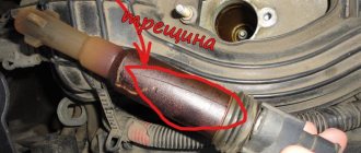
In order to reduce the toxicity of exhaust gases, VAZ-21114 and VAZ-21124 engines are equipped with catalytic converters and oxygen sensors. Oxygen sensors used on VAZ-21114 and VAZ-21124 engines are not interchangeable with oxygen sensors installed on VAZ-2111 and VAZ-2112 engines.
The oxygen sensor of the VAZ-21114 and VAZ-21124 engines differs in appearance from the previous model in the corrugated seal (1) and the shape of the tip (2) with holes
The new generation of oxygen sensors are smaller in size and have a thermal capacity, so they warm up more intensively and come into operation faster.
Especially for VAZ engines with a volume of 1.6 liters, a so-called catalytic collector was developed: an exhaust manifold made integral with the converter and installed in place of the exhaust pipe (see Exhaust system of VAZ-21114 and VAZ-21124 engines). The cathode collector is necessary to speed up the warming up of the neutralizer, which begins to work only after heating to 300 °C, and is most effective at 400–600 °C. To reduce heat loss, the exhaust pipes and catalytic collector body are made of steel and have less weight and length than the exhaust tract parts of the previous design. The location of the neutralizer (catcollector) in the engine compartment also made it possible to reduce the fire hazard by moving the hot neutralizer from under the bottom of the car.
To ensure that the concentration of harmful substances in exhaust gases complies with Euro-2 standards, VAZ-21114 and VAZ-21124 engines are equipped with a neutralizer and one oxygen sensor installed in the exhaust system before the neutralizer (in the upper part of the catalytic converter).
In the control system of an engine that complies with Euro-3 standards (cars with such engines are intended mainly for export), two oxygen sensors are used: the second - diagnostic - is installed after the converter in the lower part of the catalytic converter. By comparing the readings of two sensors, the control system evaluates the efficiency of the neutralizer and its condition. Having detected deviations, it adjusts the composition of the air-fuel mixture to reduce toxicity at the engine outlet (the “Check engine” lamp may light up on the instrument panel).
The engine management system diagnoses elements to reduce toxicity, monitors the occurrence of deviations or misfires in the ignition of the air-fuel mixture in the engine cylinders (this is when the toxicity of exhaust gases increases sharply) and warns the driver about this, neutralizing the consequences if possible. The reasons for uneven engine operation may be interruptions in spark formation, a violation of the air-fuel mixture, engine wear or failure of its parts. Misfires are monitored by the crankshaft position sensor, which reacts to the occurrence of uneven rotation of the crankshaft.
When deviations in engine operation occur that do not lead to a sharp increase in exhaust gas toxicity, the “Check engine” lamp lights up on the instrument panel. If there is a threat of failure of the converter, the “Check engine” lamp begins to flash, additionally attracting the driver’s attention. In this case, the control system stops supplying fuel to one or two “problem” cylinders, turning off the injectors, which is only possible on engines with phased fuel injection.
Also, the engine management system on cars that comply with Euro-3 standards includes a rough road sensor mounted in the engine compartment on the left mudguard of the body. This sensor temporarily disables the diagnostic system if engine roughness is not due to misfire, but occurs as a result of variable loads on the transmission when driving on rough roads.
The engine, equipped in accordance with Euro-3 toxicity standards, stabilizes speed faster immediately after start-up and runs very smoothly. When driving, the driver may notice a slow response of the car in the initial phases of engine braking and a somewhat delayed response to releasing the gas, especially in higher gears, so to reduce speed it is necessary to engage lower gears more often or apply more pressure to the brakes. Also, unlike the “sharp” carburetor version, a car with a fuel injection system and an engine that complies with Euro-3 standards responds more softly to pressing the gas pedal.
Removing ignition coils and spark plugs from a VAZ-21124 engine
Disconnect the negative cable terminal from the battery terminal. Overcoming the resistance of the rubber holders, remove the plastic engine cover.
Disconnect the wire block from the ignition coil.
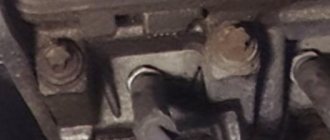
Use a 10mm socket to unscrew the coil mounting bolt.
We pry up the coil flange with a screwdriver...
...and remove the ignition coil.
If necessary, remove and replace the coil O-ring.
Original parts and their analogues: which is better
Despite the fact that this vehicle model ceased production more than 10 years ago, it is not difficult to purchase original starters made by AvtoVAZ. Moreover, their quality is not always higher than their analogues. Original part:
| Manufacturer's name | vendor code | Options | Cost, rubles |
| AvtoVAZ | 2112-3708010. | 9 bendix teeth 3 mounting bolts | From 4 000 |
There are many analogues on sale from a variety of manufacturers. The cost fluctuates quite significantly. The following manufacturers have proven themselves to be good:
| Manufacturer's name | vendor code | Options | Cost, rubles |
| StartVolt | 2110-3708010-00 | 1.5 kW | From 2 800 |
| KENO | KNV-3708010-31 | 2 kW | From 3 000 |
| ELPROM ELHOVO | ST2110E | 1.5 kW | From 3 100 |
Bosch starters have proven themselves to be good. This manufacturer carries out quality control. There is no chance of purchasing a product that does not work. It should also be noted that different manufacturers may produce parts of different sizes.
For example, the Bosch starter is slightly larger than the KEHO starter. The price of the part will vary significantly depending on the manufacturer. The difference between the dimensions can be seen in the photo. Larger parts will be difficult to install.
Equipment for VAZ 2112 passenger cars
| Automobile model | VAZ 2112 | VAZ 2112-01 | VAZ 2112-02 |
| Body type | All-metal, monocoque hatchback | ||
| engine's type | 16-valve with distributed fuel injection, V=1500 cm3 | ||
| Execution | "Standard" | "Norm" | "Lux" |
| Option code | 110, 115, 117, 122, 125, 130, 133, 134, 135, 137 GM (s.h.) 10 | 10, 13, 14, 19, 110, 115, 117, 122, 125, 130, 133, 134, 135, 136, 137 | 10, 11, 14, 16, 19, 110, 115, 117, 122, 125, 130, 133, 134, 136, 137 |
| Automobile model | VAZ 21122 | VAZ 21122-01 | VAZ 21122-02 |
| Body type | All-metal, monocoque hatchback | ||
| engine's type | 8-valve with distributed fuel injection, V=1500 cm3 | ||
| Execution | "Standard" | "Norm" | "Lux" |
| Option code | 10, 11, 13, 20, 21, 110, 115, 117, 119, 122, 124, 125, 130, 133, 134, 135, 136, 137 GM (c.c.) 11 | 10, 13, 19, 20, 30, 40, 110, 115, 117, 119, 122, 124, 125, 130, 133, 134, 135, 136, 137 | 10, 11, 16, 19, 20, 30, 40, 110, 115, 117, 119, 122, 124, 125, 130, 133, 134, 135, 137 |