The VAZ 2114 (Samara-2) car is built on the VAZ 21093 platform and is an improved version of the car. The first prototype of the hatchback was assembled back in 2000. A year later, the Volzhsky Automobile Plant produced the first pilot production batch of 50 cars, and in the same 2001, the hatchback was first introduced to the market. The interior received a new instrument panel, a new steering wheel, an adjustable steering column, power windows and a new heater, which naturally affected the electrical circuit of the VAZ 2114.
The fourteenth model was previously equipped with a 1.5 liter eight-valve engine, borrowed from the VAZ 2111 model with an injector. A little later it was replaced by the VAZ 11183-1000 version, which complies with the Euro-3 standard. The VAZ 2114 injector received a more powerful motor, and this is one of the reasons that the wiring of the 2114 has also changed.
A wiring harness has been added for connecting to the electronic switch. A harness has also appeared for connecting to the ignition module terminal.
Replacing high-voltage wires will require additional attention, because the connection procedure depends on the year of manufacture of the car. Until 2004, 4-pin ignition modules were installed, and after that - 3-pin. Connecting the adsorber valve to the injection system controller also provided another additional element. An adsorber is an electromechanical device used for ventilation and removal of condensate in a gas tank. Complications also affected the interior part. The dashboard received improvements in the form of the appearance of a BC (on-board computer), a new instrument panel and a change in the position of the glove compartment.
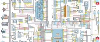
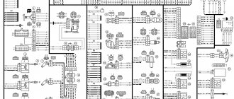
General wiring diagram
- Headlights;
- Geared motors for headlight cleaners;
- Fog lights;
- Ambient temperature sensor;
- Sound signals;
- Engine compartment lamp switch;
- Engine cooling fan electric motor;
- Generator;
- Low oil level indicator sensor;
- Washer fluid level sensor;
- Front brake pad wear sensors;
- Wire ends connected to the common windshield washer pump*;
- Windshield washer pump;
- Headlight washer pump;
- Wire lugs for connecting to the rear window washer pump on VAZ-2113 and VAZ-2114 cars;
- Low oil pressure indicator sensor;
- Engine compartment lamp;
- VAZ-2111 engine:
Wire lug for connection to the wiring harness of the engine control system
VAZ-21083 engine:
Electric fan switching sensor; - Windshield wiper gear motor;
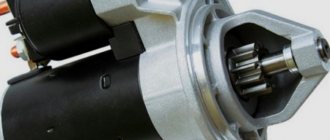
- Starter;
- VAZ-21083 engine:
Block connected to the ignition system wiring harness; - Coolant temperature indicator sensor;
- Reversing light switch;
- Insufficient brake fluid level indicator sensor;
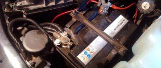
- Accumulator battery;
- Insufficient coolant level indicator sensor;
- Relay for turning on fog lights;
- Mounting block;
- Brake light switch;
- Portable lamp socket;
- Illumination lamp for the headlight hydrocorrector scale;
- Parking brake warning lamp switch;
- Block for connecting a backlight lamp;
- Instrument cluster lamp switch;
- Understeering's shifter;
- Hazard switch;
- Front seat heating element relay;
- Ignition switch;
- Rear fog light circuit fuse;
- Front seat heating elements circuit fuse;
- Door lock circuit fuse;
- Front ashtray illumination lamp;
- Ignition relay;
- Cigarette lighter;
- Glove compartment lamp;
- Glove compartment lamp switch;
- Heater fan motor;
- Additional resistor for heater fan motor;
- Heater fan switch;
- Heater fan switch illumination lamp;
- Heater lever illumination lamp;
- Gear motors for power windows of front doors;
- Right front door power window switch (located in the right door);
- Gear motors for locking front door locks;
- Wires for connecting to the right front speaker;
- Rear door locking motors;
- Wires for connecting to the right rear speaker;
- Door lock control unit;
- Wires for connection to radio equipment;
- Headlight wiper switch;
- Rear window heating element switch;
- Relay for turning on rear fog lights;
- Block for connection to the heating element of the right front seat;
- Rear fog light switch;
- Right front seat heating element switch;
- Fog light switch;
- Outdoor lighting switch;
- Left front seat heating element switch;
- Block for connection to the heating element of the left front seat;
- Wires for connecting to the left front speaker;
- Left front door power window switch (located in the left door);
- Right front door power window switch (located in the left door);
- Wires for connecting to the left rear speaker;
- Side direction indicators;
- Lamp switches on the front door pillars;
- Light switches on the rear door pillars;
- Central interior lamp;
- Front interior lamp;
- Block for connecting to the wiring harness of the electric fuel pump;
- Trunk light switch;
- Instrument cluster;
- Trunk light;
- On-board control system signaling unit;
- Trip computer;
- VAZ-2111 engine:
Block for connecting the wiring harness of the engine control system; - Rear exterior lights;
- Rear interior lights;
- Pads for connecting to the rear window heating element;
- License plate lights;
- Additional brake signal located in the spoiler.
The order of conditional numbering of plugs in blocks:
- A - Headlights and headlight cleaners;
- B - Cigarette lighter;
- B - Mounting block, instrument cluster, ignition switch, windshield wiper and other electrical components (for blocks with a different number of plugs, the numbering order is similar);
- G — Relay for turning on the rear fog light;
- D - Hazard switch;
- E - Geared motors for electric windows and geared motors for locking door locks;
- F - Central interior lamp.
Features of the VAZ-2114 electrical wiring:
- In the instrument panel wiring harness, the second ends of the white wires are brought together into one point, which is connected to the instrument cluster lighting switch (except for the white wire, from plug “4” of block “X2” of mounting block 28 to display block 83 of the on-board control system).
- The second ends of the black wires are also brought together to points connected to ground.
- The second ends of the yellow wires with a blue stripe are brought together to a point connected to plug “4” of the “X1” block of the mounting block.
- The second ends of the white wires with a red stripe are brought together to a point connected to plug “10” of the “X4” block of the mounting block.
- The second ends of the orange wires are brought together to a point connected to plug “3” of the “X4” block of the mounting block.
- * On vehicles of various configurations, one common washer pump and electromagnetic valves for headlight and windshield washers can be installed (as on VAZ-2108, -2109 vehicles). In this case, the pads 12 are connected to the washer pump, and the wires connected to pumps 13 and 14 are connected to the corresponding solenoid valves.
Types of VAZ 2114 passenger cars
- VAZ 2114-20 is a passenger car with a hatchback body in a standard version, with a 1.5-liter VAZ 2111 engine with distributed injection. All VAZ 2114 models were produced with a transverse engine installation. Produced under environmental class Euro 2, 3, 4.
- VAZ 2114-21 is a passenger car with a hatchback body in the “norm” class version with a 1.5-liter VAZ 2111 engine. On all modifications of this machine, the engine was installed across the axis. This model was produced for environmental class Euro 3 and 4.
- VAZ 2114-22 is a passenger car with a hatchback body and a 1.5-liter VAZ 2111 model engine located transverse to the body axis. It was produced in a luxury version for environmental class Euro 2, 3, 4.
- VAZ 21144-20 is a passenger car with a hatchback body and a VAZ 11183 engine with a volume of 1.6 liters. On all cars, the engine was mounted across the body axis. It was produced in a “standard” version with distributed gasoline injection in the engine.
- VAZ 21144-22 is a luxury passenger car with a hatchback body. It was produced with a transverse VAZ 11183 engine relative to the body axis and with a volume of 1.6 liters. This modification of the VAZ 2114 was produced to Euro 2, 3 toxicity standards.
Engine control circuit (January 5.1, Bosch M1.5.4N)
- Fragment of the mounting block;
- Electric engine cooling fan;
- Automotive anti-theft system status indicator;
- Automotive anti-theft system control unit;
- Coolant temperature sensor;
- Air flow sensor;
- Throttle pipe;
- Block connected to the throttle position sensor;
- Block attached to the idle speed control;
- Controller;
- A block connected to the air conditioner wiring harness;
- Oxygen sensor;
- Knock sensor;
- Crankshaft position sensor;
- Speed sensor;
- Adsorber;
- Accumulator battery;
- Main relay;
- A block connected to the anti-lock brake system wiring harness;
- Diagnostic block;
- Main relay circuit protection fuse;
- Controller protection fuse;
- Fuse for protecting the electric fuel pump and its relay;
- Relay for turning on the electric fuel pump;
- Electric fan switch relay;
- A block connected to the instrument panel wiring harness;
- A block connected to the instrument panel wiring harness;
- Ignition module;
- Electric fuel pump with fuel level sensor;
- Spark plug;
- Injectors;
- F — Front harness wire going to the “B+” terminal of the generator;
- G - Front wiring harness wires.
The order of conditional numbering of plugs in blocks:
- A - Controller;
- B — Control unit of the automobile anti-theft system;
- B — Indicator of the status of the automobile anti-theft system;
- G - Pads 26;
- D - Throttle pipe;
- E - Air flow sensor;
- F - Electric fuel pump and oxygen sensor;
- 3 — Speed sensor;
- And - Ignition module.
Purpose of plugs in block 26:
- To the low-voltage tachometer input in the instrument cluster;
- —
- To the engine management system control lamp in the instrument cluster (from the controller);
- To the dome light switch located on the driver's door pillar;
- To the engine control system control lamp in the instrument cluster (+ power supply);
- To the trip computer (fuel consumption signal);
- To the instrument cluster (vehicle speed signal);
- To terminal “15” of the ignition switch (plug 4 of the switch block).
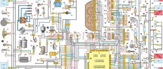
Diagram of VAZ 2114 injector 8 valves
The front part of the VAZ 2114 diagram
Rear part of the VAZ 2114 diagram
Complete electrical diagram of VAZ 2114
Below is a complete electrical diagram of the VAZ 2114 injector. This VAZ model was equipped with one type of engine - an eight-valve injection VAZ 2111-86. This is his diagram of a VAZ 2114 injector with 8 valves. It includes a variety of local circuits of individual devices. For example, such as the cooling diagram for the VAZ 2114 injector and the fuse diagram for the VAZ 2114 injector. Local diagrams are located just below.
| Position number on the diagram | Decoding the device position |
| 1 | headlight |
| 2 | fog light |
| 3 | DTV VAZ 2114 |
| 4 | electric motor radiator fan |
| 5 | terminal block for connection to a bundle of wires to the power unit control structure |
| 6 | engine compartment light switch |
| 7 | * spare terminal block for connecting a signal with one output (the minus is connected to the body) |
| 8 | sound signal |
| 9 | fluid position sensor in the windshield washer tank |
| 10 | * pad wear sensor |
| 11 | oil level sensor |
| 12 | Magneto VAZ-2114 |
| 13 | * engine compartment lamp |
| 14 | temperature indicator sensor |
| 15 | starter VAZ-2114 |
| 16 | VAZ 2114 battery |
| 17 | * connector for fog lights |
| 18 | antifreeze position device in the expansion tank |
| 19 | brake fluid level sensor |
| 20 | rear traffic light switch |
| 21 | windshield wiper gear motor |
| 22 | emergency oil pressure gauge |
| 23 | rear window washer electric pump |
| 24 | electric windshield washer pump |
| 25 | instrument panel VAZ 2114 |
| 26 | fuse and relay block |
| 27 | brake light switch |
| 28 | ignition relay |
| 29 | ignition switch |
| 30 | board light bulb |
| 31 | glove box light switch |
| 32 | rear window heating switch |
| 33 | rear fog light switch |
| 34 | * front fog light switch |
| 35 | composite switch for headlights and headlights; |
| 36 | hazard warning light switch |
| 37 | steering column switches |
| 38 | instrument backlight brightness control |
| 39 | Illumination lamp for the headlight hydraulic adjustment control handle |
| 40 | portable socket |
| 41 | side turn signal |
| 42 | interior light switch (front door open sensor) |
| 43 | interior lamp |
| 44 | electric fan structure ventilation and heating |
| 45 | additional resistance of the electric fan of the ventilation and heating network |
| 46 | switch for operating modes of the electric fan of the ventilation and heating structure |
| 47 | Illumination lamp for the operating mode switch handle of the electric fan of the ventilation and heating network |
| 48 | heater ecu light bulb |
| 49 | on-board control network display unit |
| 50 | * trip computer VAZ 2114 |
| 51 | interior light switch (rear door open sensor) |
| 52 | terminal block for connecting a clock* |
| 53 | gasoline module |
| 54 | ashtray light bulb |
| 55 | cigarette lighter VAZ 2114 |
| 56 | interior light lamp |
| 57 | Parking brake control switch |
| 58 | back light |
| 59 | room lighting bulbs |
| 60 | additional brake light |
| 61 | rear window heater |
| 62 | rear window wiper gear motor |
| A | terminal numbers in connecting blocks |
.
* Installed on some cars.
The electrical diagram of the VAZ 2114 injector (depending on the year of production and configuration) may differ from the diagram presented above in the colors of some wires and the number of additional equipment.
Engine control circuit - Euro-2 (Bosch MP7.0)
- Fragment of the mounting block;
- Electric engine cooling fan;
- Automotive anti-theft system status indicator;
- Automotive anti-theft system control unit;
- Coolant temperature sensor;
- Air flow sensor;
- Throttle pipe;
- Block connected to the throttle position sensor;
- Block attached to the idle speed control;
- Controller;
- A block connected to the air conditioner wiring harness;
- Oxygen sensor;
- Knock sensor;
- Crankshaft position sensor;
- Speed sensor;
- Adsorber;
- Accumulator battery;
- Main relay;
- A block connected to the anti-lock brake system wiring harness;
- Diagnostic block;
- Main relay circuit protection fuse;
- Controller protection fuse;
- Fuse for protecting the electric fuel pump and its relay;
- Relay for turning on the electric fuel pump;
- Electric fan switch relay;
- A block connected to the instrument panel wiring harness;
- A block connected to the instrument panel wiring harness;
- Ignition module;
- Electric fuel pump with fuel level sensor;
- Spark plug;
- Injectors.
- F — Front harness wire going to the “B+” terminal of the generator;
- G - Front wiring harness wires.
The order of conditional numbering of plugs in blocks:
- A - Controller;
- B — Control unit of the automobile anti-theft system;
- B — Indicator of the status of the automobile anti-theft system;
- G - Pads 26;
- D - Throttle pipe;
- E - Air flow sensor;
- F - Electric fuel pump and oxygen sensor;
- 3 — Speed sensor;
- And - Ignition module.
Purpose of plugs in block 26:
- To the low-voltage tachometer input in the instrument cluster;
- —
- To the engine management system control lamp in the instrument cluster (from the controller);
- To the dome light switch located on the driver's door pillar;
- To the engine control system control lamp in the instrument cluster (+ power supply);
- To the trip computer (fuel consumption signal);
- To the instrument cluster (vehicle speed signal);
- To terminal “15” of the ignition switch (plug 4 of the switch block)
Scheme 2114 engine injector VAZ 11183 (l,6i)
| Position number on the diagram | Explanation of the position on the diagram |
| 1 | spark plug 4 pots VAZ 2114 model A17DVRM (ZAZS) |
| 2 | spark plug 3 pots VAZ 2114 model LR15YC-1 (BRISK "SUPER") - as an option |
| 3 | spark plug 2 pots VAZ 2114 model WR7DC(BOSCH) - as an option |
| 4 | spark plug 1 pot VAZ 2114model BPR6ES(NGK) - as an option |
| 5 | Ignition solenoid VAZ 2114 model 2111-3705010-02 (54.37005) |
| 6 | diagnostic connector terminal block |
| 7 | 1 cylinder sprayer |
| 8 | 2 pot injector |
| 9 | sprinkler 3 pots |
| 10 | 4 cylinder injector; |
| 11 | controller |
| 12 | Gasoline pump connection connector |
| 13 | to the engine radiator fan |
| 14 | Engine radiator fan switch switch |
| 15 | main switch of the propulsion control system |
| 16 | dmrv |
| 17 | dpdz |
| 18 | dtozh |
| 19 | empty control |
| 20 | canister purge throttle |
| 21 | dpkv |
| 22 | dd |
| 23 | oxygen concentration meter |
| 24 | to the ignition switch |
| 25 | immobilizer computer |
| 26 | immobilizer sensor with warning light |
| 27 | car speed meter |
| 28 | additional terminal block |
| 29 | to the battery positive |
| 30 | dprv |
| 31 | terminal block for connecting to the car's electrical network |
| 32 | gasoline module |
| F1 | fuse for controller and motor control system connections |
| F2 | ECU fuse |
| F3 | fuel pump circuit fuse |
Diagram of the heater and heated rear window
- Mounting block;
- Ignition switch;
- Ignition relay;
- Heater motor switch;
- Additional resistor;
- Heater motor;
- Rear window heating switch with turn-on indicator lamp;
- Rear window heating element;
- K7 - Relay for turning on the heated rear window.
Possible causes of signal failure
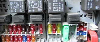
1) Fuse blown
A voltage surge in the vehicle's on-board network can damage any electronic element, therefore, to avoid such a problem, fuses are provided, incl. and on the sound element. A blown fuse is a common situation, so when attempting to carry out repairs on your own, you should first check its condition. The fuse responsible for the sound supply in the VAZ 2114 is located in the mounting block. You can study the exact location of the element in the diagram below of the new sample mounting block. The fuse for monitoring and turning on the sound signal in the new type mounting block is designated by the combination F5 and is located in the left column of fuses (fifth in a row). The fuse current installed in the block socket should be 20 Amperes. Almost any car store or gas station sells kits, including 20 Ampere fuses.
Important! To conveniently replace a burnt-out element, use a special paperclip, which comes in a package with other fuses. Such a clip is located in all car mounting blocks from the factory, but over time most car enthusiasts lose it.
2) Failure of the electrical relay
The second most common problem is the burnout of the main relay, which is responsible for the operation of the car’s horn. This relay is located in the same mounting block along with the fuses. Unlike fuses, relays can be replaced without using a paperclip. The diagram below shows the relay responsible for the signal. To select a new relay, just visit any spare parts store for domestic cars, where they will provide you with a suitable relay. For self-checking, you can replace the failed switching device with an adjacent heated rear window relay, marked in the diagram with the combination K7.
3) Signal button failure
In addition to electrical elements, the circuit of the entire signal structure also contains mechanical parts, which over time can break or completely wear out. A button is just one such element. In the design of the VAZ 2114, this button is a plate that, when the steering pad is pressed, closes and voltage is sent to the signal itself under the hood. Periodically checking these elements for contamination can save you from sticking of the plates and their premature wear. It is worth noting that the steering pad on the VAZ 2114 can be removed quite easily using a Phillips screwdriver.
4) Wear of the slip ring
The problem due to slip ring wear occurs on cars with high mileage, or on cars where low-quality structural parts were installed. The photo below shows two slip rings, one of which is worn out. Even from the photograph you can see that the ring on the left has a large hole, due to which the sound supply may work every once in a while or not work at all. This problem is solved by replacing the ring with a new one.
5) Oxidation of contacts on the steering wheel
Moisture getting into the steering wheel housing or the age of the car are the two main reasons why the contacts on the steering wheel become oxidized. Poor contact at the junction of the wires and the plate may cause the signal to fail. To solve the problem, remove the steering wheel pad and the top plate, then clean the wires from oxides. Lubricants can also be used to seal out moisture.
6) Horn failure
Failure due to wear or sticking of the membrane is rare, but still possible. The design of the VAZ 2114 signal itself is quite reliable, but it also periodically fails. This “snail” is located right under the hood near the car’s radiator. Sometimes, to “unstick” the membrane, it is enough to hit the body. If this does not help, you can always disassemble the case and clean the mechanism. As a last resort, you can buy a new “snail”, since its cost is 300-400 rubles.
7) Broken wiring
The last reason for a possible failure of the mechanism is a broken wiring. Often this problem occurs after work has been carried out to install an alarm system, additional devices or other implementation into the standard wiring of the machine. Wiring rotting is also a common situation. The problem is solved by completely replacing the wiring of the electrical circuit. In general, almost any reason for a non-working signal from the list above can be eliminated quite easily (and on your own), so you should not worry and look for all the design elements in the store.
Detailed color diagrams of the VAZ 2114 wiring (carburetor, injector) are provided with a description of the electrical equipment for various modifications. The information is intended for self-repair of cars. Many electrical circuits are divided into several sections for ease of viewing via a computer or smartphone; there are also circuits in the form of one picture with a description of the elements - for printing on a printer.
The VAZ 2114 (Samara-2) car is built on the VAZ 21093 platform and is an improved version of it. The first prototype of the hatchback was assembled back in 2000. A year later, the Volzhsky Automobile Plant produced the first pilot batch of 50 VAZ-2114 cars, and in the same 2001 the hatchback was first introduced to the market. The interior features a new instrument panel, a new steering wheel, an adjustable steering column, power windows and a new heater. Years of production 2114: 2001—2013
The fourteenth model was previously equipped with a 1.5 liter eight-valve engine, borrowed from the VAZ 2111 model with an injector. A little later it was replaced by the VAZ 11183-1000 version, which complies with the Euro-3 standard. The VAZ 2114 injector received a more powerful engine, and this is one of the reasons that the wiring of the 2114 has also changed.
A wiring harness has been added for connecting to the electronic switch. A harness has also appeared for connecting to the ignition module terminal.
Replacing high-voltage wires will require additional attention, because the connection procedure depends on the year of manufacture of the car. Until 2004, 4-pin ignition modules were installed, and after that - 3-pin. Connecting the adsorber valve to the injection system controller also provided another additional element. An adsorber is an electromechanical device used for ventilation and removal of condensate in a gas tank. Complications also affected the interior part. The dashboard received improvements in the form of the appearance of a BC (on-board computer), a new instrument panel and a change in the position of the glove compartment.
Diagram of low beam, high beam, rear fog lamps
- Headlights;
- Mounting block;
- Headlight switch;
- Ignition switch;
- External lighting switch (fragment);
- Fog lamps in the interior rear lights;
- Fog light switch with turn-on indicator lamp;
- Headlight high beam indicator lamp in the instrument cluster;
- K8 - High beam headlight relay;
- K9 - Relay for low beam headlights;
- A - The order of conditional numbering of plugs in the headlight block;
- B - to power supplies.
Additional diagrams of electrical devices and systems of VAZ 2114
Electrical diagram for connecting the coolant temperature sensor VAZ 2114
| This page contains an electrical diagram for connecting the VAZ 2114 coolant temperature sensor. It shows how the DTOZh is connected to the engine control controller. The sensor is shown in this diagram with its internal electrical circuit. For ease of reading and understanding of this diagram, it shows the terminal block of the temperature sensor |
Diagram of side lights, brake lights, interior lighting
- Side light bulbs in headlights;
- Engine compartment lamp;
- Mounting block;
- Engine compartment lamp switch;
- Ignition switch;
- External lighting switch (fragment);
- External lighting indicator lamp in the instrument cluster;
- Lamps for side lights and brake lights in the outer rear lights;
- License plate lights;
- Instrument lighting regulator;
- Brake light switch;
- On-board control system unit;
- K4 - Relay for monitoring the health of lamps (contact jumpers are shown inside the relay, which must be installed in the absence of a relay);
- A - to power supplies;
- B - to the backlight lamps of switches and devices;
- C - to an additional braking signal.
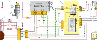
Electrical diagram for connecting the VAZ 2114 generator model 94.3701
Generator 94.3701 is a synchronous AC electrical machine with electromagnetic excitation with a built-in rectifier based on silicon diodes and an electronic voltage regulator
| Position number on the diagram | Explanation of the position on the diagram |
| 1 | battery |
| 2 | generator VAZ 2114 model 94.3701 |
| 3 | fuse box |
| 4 | battery charge indicator lamp located in the instrument cluster |
| 5 | egnition lock |
The current to excite the generator when the ignition is connected is supplied to terminal “D+” of the regulator (terminal “D” of the generator) through signal light 4 installed in the instrument cluster. After starting the motor, the excitation winding is powered by three additional diodes mounted on the generator rectifier block. The operation of the generator is monitored by a warning light on the dashboard. When the ignition is connected, the light should be on, and after starting the engine, it should go out when the generator is working. A bright glow of the light bulb or its burning at half intensity indicates a malfunction of the generator.
Scheme for testing generator 94.3701 on a stand
| Position number on the diagram | Explanation of the position on the diagram |
| 1 | control 12V, 3W |
| 2 | magneto |
| 3 | voltmeter |
| 4 | rheostat |
| 5 | ammeter |
| 6 | switch |
| 7 | source of electricity |
After running the generator on the stand for 10 minutes, with the rotor rotating at a speed of 6000 rpm, the output current of a working generator brand 94.3701 should be at least 80 A.
Diagram for testing additional generator diodes 94.3701
The short circuit of the additional diodes of the generator 94.3701 can be checked on the car, without removing the generator from it, according to the diagram below. In this case, you need to disconnect the wires from the battery and generator, remove the protective casing of the generator and disconnect the wire from the “D+” contact of the voltage regulator.
If the light is on, then there is a short circuit in one of the additional diodes. A break in additional diodes can be determined by the low voltage at contact “D” at an average rotation speed of the generator armature.
Generator rectifier valve test diagram 94.3701
A working valve allows electricity to flow only in one direction, but a broken valve does not allow electricity to pass through (open circuit), or allows current to flow in both directions (short circuit).
When the light is on, when checking according to diagram “I”, the “negative” and “positive” valves have a short circuit. When checking the valves according to scheme “II”, the light on the lamp indicates a short circuit of one or more positive valves. The glow of the light bulb, when checking the valves according to scheme “III”, means a short circuit in 1 or several “negative” valves. You should be aware that in this case the glow of the light bulb may also be a consequence of the short circuit of the stator winding turns to the generator housing. However, such a breakdown is much less common than valve short circuits.
| Position number on the diagram | Explanation of the position on the diagram |
| 1 | source of electricity |
| 2 | control |
| 3 | magneto |
| I | control of “plus” and “minus” valves at once |
| II | control of positive valves |
| III | control of negative valves |
Diagram of direction indicators and hazard warning lights
- Turn signal lamps;
- Mounting block;
- Ignition switch;
- Hazard switch;
- Side turn signal lamps;
- Turn signal lamps in the outer rear lights;
- Turn signal lamps in the instrument cluster;
- Turn signal switch;
- K2 - Relay interrupter for direction indicators and hazard warning lights;
- A - to power supplies.
What are fog lamps for?
The first prototype of the hatchback was assembled back in the year. And in combination with high-quality manufacturing materials, it ensured reliable operation. Many PTF kits contain special decorative plugs that add attractiveness and neatness to the installed headlights and facilitate the installation process. To summarize, we can say that in the first case, the qualifications of the work are minimal, and it can be done by yourself, without having specific knowledge, while working with an electrician requires a specialist who needs to be paid. When purchasing a bumper with holes for fog lights, you will need to purchase the lights themselves and all the necessary components for connection. Self-installation of PTF is the most common installation method, since it requires minimal financial investment. Otherwise, the clip fastening can be broken, and during subsequent installation the casing will not sit tightly in place.
There is a gear on the motor shaft that meshes with the teeth of the rack.
It should fit between the door clip and the door frame. Driver's door switch button. Installation of the VAZ 2114 engine start button. Do-it-yourself installation.
Front fog lamp diagram
- Fog lights;
- Relay for turning on fog lights;
- Mounting block;
- Fog light switch with turn-on indicator lamp (left) and backlight lamp (right);
- External lighting switch (fragment);
- A - to power supplies;
- B - to the instrument lighting regulator.
Electrical diagram of the ignition coil VAZ 2114 8 valves
| This page shows an electrical diagram for connecting the ignition coil of a VAZ 2114 model 2111-3705010 to the electronic control unit. This diagram shows the ignition coil with its electrical circuit. It makes it possible to understand its internal structure and the principle of its operation. As can be seen from the diagram, the coil has a three-pin terminal block for connecting thin wires and four pins for connecting high-voltage cables that supply a high-voltage pulse to 4 spark plugs. |
Front wiper and washer diagram
- Windshield washer motor;
- Windshield wiper motor;
- Mounting block;
- Ignition switch;
- Ignition relay;
- Windshield wiper and washer switch;
- Short circuit - Windshield wiper relay;
- A - to power supplies;
- B - The order of conditional numbering of the plugs in the block of the wiper motor.
Important diagrams of the main electrical devices and systems of the VAZ 2114
Ignition switch terminal connection diagram
| Position number on the diagram | Explanation of the position on the diagram |
| 1 | terminal group of the ignition switch (lock) (0 - “off”: I - “on”; II - “starter”) |
| 2 | light bulb |
| 3 | small switch |
| 4 | wire harness block |
Mounting block connection diagram
The outer number in the designation of the wire tip is the number of the block, the inner number is the conventional number of the tip.
- K1 - Relay for turning on headlight cleaners;
- K2 - Relay interrupter for direction indicators and hazard warning lights;
- Short circuit - Windshield wiper relay;
- K4 - Relay for monitoring the health of lamps;
- K5 - Relay for turning on power windows (in a variant version of the car);
- K6 - Relay for turning on sound signals;
- K7 - Relay for turning on the heated rear window;
- K8 - Headlight high beam relay;
- K9 - Relay for low beam headlights;
- F1-F16 - Fuses.
Replacement and repair of VAZ sound signal
The most common reason for the absence of a sound signal lies in the signals themselves. The reason is mechanical, moisture and oxidation lead to blocking of the sound membrane and, as a result, the absence of vibrations and sound effect. Sometimes you can restore functionality by spraying the signal with WD-40 or a similar composition.
Video:
On cars, where two signals are installed, as a rule, they are of different tones, low and high. If one signal fails, the second will not be able to fully provide the required power, and therefore requires replacement. As a rule, many signals are equipped with a tone adjustment screw, and if there are wheezing, grinding and other unwanted sound effects, you can use the adjustment to achieve a suitable sound. Also, with their help, you can move the “soured” membrane, thereby restoring the functionality of the signal.
Car modifications 2114
VAZ-211440. Another modification released in 2007, it was equipped with a VAZ-11183 engine with a volume of 1.6 liters and a power of 82 horsepower. The car was discontinued in 2013.
VAZ-211440-24. Released in 2009, a modification with an injection 16-valve VAZ-21124 engine with a volume of 1.6 liters and a power of 89.1 horsepower. Discontinued in 2013.
VAZ-211440-26. Modification with a 16-valve injection engine VAZ-21126, which complies with the Euro-3 environmental standard, with a volume of 1.6 liters and a power of 98 hp. The car was produced from 2010 to 2013.