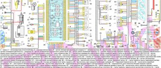
1 – ignition coils 2 – injectors 3 – controller 4 – main relay 5 – fuse connected to the main relay 6 – cooling system electric fan relay 7 – fuse connected to the cooling system electric fan relay 8 – electric fuel pump relay 9 – fuse connected to electric fuel pump relay 10 – mass flow and air temperature sensor 11 – throttle position sensor 12 – coolant temperature sensor 13 – canister purge solenoid valve 14 – oxygen sensor 15 – knock sensor 16 – crankshaft position sensor 17 – idle speed control 18 – immobilizer control unit 19 – immobilizer status indicator 20 – phase sensor 21 – vehicle speed sensor 22 – electric fuel pump module with fuel level sensor 23 – oil pressure warning lamp sensor 24 – coolant temperature indicator sensor
A – block connected to the wiring harness of the ABS cabin group B – diagnostic block C – block connected to the air conditioner wiring harness D – to the “+” terminal of the battery D – to the side door wiring harness block E – block connected to the panel wiring harness devices
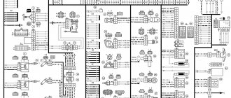
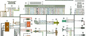
VAZ-2112 wiring diagram
Wiring diagram for a car in a hatchback body (click on the picture to enlarge)
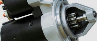
Designations: 1 – Headlight, 2 – Horn, 3 – Main radiator fan, 4 – Starter, 5 – Battery, 6 – Generator, 7 – Gearbox limit switch (reverse), 8 – Actuator in the front passenger door, 9 – Relay power windows permissions, 10 – Starter relay, 11 – Heater fan, 12 – Electric heater partition drive, 13 – Main pump, 14 – Washer reservoir sensor, 15 – Driver’s door actuator, 16 – Front passenger window selector, 17 – Fifth wheel release button doors, 18 – Heater fan resistance unit, 19 – Main wiper motor, 20 – Driver's window lift selector, 21 – Front passenger's window lift motor, 22 – Central locking, 23 – Exterior light switch, 24 – Brake fluid leakage sensor, 25 – Additional pump , 26 – Driver's window lift motor, 27 – PTF on indicator, 28 – PTF switch, 29 – Dashboard , 30 – Heated glass on indicator, 31 – Heated glass switch, 32 – Steering column selector switch, 33 – PTF relay, 34 – Ignition switch , 35 – Main fuse block, 36 – Illumination of heater controls, 37 – Hazard warning button, 38 – Heater control controller, 39 – Glove compartment lighting, 40 – Glove compartment lid end cap, 41 – Cigarette lighter, 42 – BSK – display unit, 43 – Ashtray illumination, 44 – 12V socket, 45 – Instrument lighting switch, 46 – Actuator in the right rear door, 47 – Right rear passenger window selector, 48 – Clock, 49 – Right rear passenger window motor, 50 – Brake limit switch (closed – pedal is pressed), 51 – Left rear passenger window motor, 52 – Left rear passenger window selector, 53 – Actuator in the left rear door, 54 – Turn signal, 55 – Handbrake limit switch (closed – handbrake on), 56 – Rear wiper motor, 57 – Navigator’s lamp, 58 – Interior lamp, 59 – Temperature sensor in the heater, 60 – Limit switch for an open front door, 61 – Limit switch for an open rear door, 62 – Trunk lighting, 63 – Rear optics (on the body), 64 – Rear optics ( on the fifth door), 65 – License plate illumination.
The letters indicate the terminals to which it is connected: A – Front speaker on the right, B – Radio, C – Injector harness, D – ESD diagnostic connector, D – Front left speaker, E – Diagnostic connector for the heater controller, G – Rear right speaker, W – Rear left speaker, I – BC connector, K – glass heater thread, L – fifth door actuator, M – Additional brake light.
All door switches remain open when the doors are closed. We provide a wiring diagram for the VAZ-2112 with a description, and information about the limit switches will be useful to signal installers.
Please note that starter power may be connected in different ways. Either the current to terminal 50 comes directly from the lock, or through relay 10. The second option (as in the diagram) is less common.
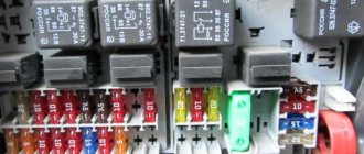
The three relays shown in the diagram are always installed on a block mounted on top of block 35 (see photo).
Main fuse and relay box
Here part 5 is “relay 9”, and part 7 is “relay 10”.
Window lifters
When the ignition is turned on, relay 11 closes its contacts. This enables the operation of the power windows controlled by selectors 3, 4, 9 and 10.
Without the ignition, the power windows don't work.
The diagram does not require any other explanation.
central locking
The diagram shows four actuators, as well as control unit 3. Actuator 7 is located in the driver's door.
Actuators, central locking unit and one limit switch
It would seem that everything is simple here. But in the description of the VAZ-2112 electrical circuit, the main thing is usually not reported: the white cord is the input for the “Open” command, the brown one is the “Close” command.
There is a variant of the circuit where module 7 contains only a limit switch (without an actuator).
Relay K4 turns on the low beam lamps, K5 - high beam.
Headlights with single-filament lamps
Selector lever 3 only switches on relay K5. But in the explanation to the electrical diagram on the VAZ-2112 it is said that:
It's simple: when switch 4 is in position II, relay K4 closes its contacts. This means that in the “high beam” mode all the lamps work at once.
Dimensions, brake light, backlight
Side lights 1 and 6 are turned on by switch 3. From it, the current flows through the main unit 2, or rather, through the lamp serviceability relay. The diagram shows jumpers instead of relay K1.
Dimensions, license plate lights, brake lights, instrument lights
The license plate lighting is lamps 8. They turn on regardless of the operation of the relay. The operation of the reverse lamps also does not depend on relay K1, as well as on switch 3. It is regulated only by limit switch 10. The brake light lamps are switched on in a similar way (limit switch 11).
The brightness of the instrument lighting is controlled by resistor 9. But there is a caveat: switch 3 must be in position I or II. These positions correspond to the inclusion of indicator 5 (on the dashboard).
Turn signals
Turn signal lamps 1, 5 and 6 are activated by switch 7. The power supply circuit for these lamps includes a relay-breaker K3, which alternately closes contacts 49a-49 and 49a-31.
The basis of the circuit is a relay-interrupter
Without power supply from the ignition switch, the turn signals do not work. There is also an “Alarm” operating mode when:
If contact is broken in the socket of one of the lamps, the operating frequency of relay K3 doubles. In normal condition, it is 1.2-1.9 Hz.
Car fuses - number, current and description
F1 5 Lighting lamps: numbers, instruments, dimensions on the dashboard, left dimensions, trunk lighting F2 7.5 Low beam in the left headlight F3 10 High beam in the left headlight F4 10 Right front fog lamp F5 30 Door windows F6 15 Portable lamp, cigarette lighter F7 20 Radiator fan, horn F8 20 Heated rear window F9 20 Windshield washer and cleaner F10 20 Reserve F11 5 Clearance on the right side F12 7.5 Low beam in the right headlight F13 10 High beam in the right headlight F14 10 Fog lamp, left F15 20 Heated seats 21124 F16 10 Hazard signal, turn signals F17 7.5 Brake light, ignition switch illumination, interior lighting F18 25 Cigarette lighter, glove compartment light, interior heater F19 10 Reversing lamp, brake light monitoring F20 7.5 Rear fog lights headlights
CAR ELECTRONICS REPAIR
VAZ-2112 diagram
The VAZ-2112 car was produced at AvtoVAZ from 1998 to 2009, in Ukraine from 2009 to 2014. The following are color wiring diagrams (injector and carburetor) with a description of all elements for various modifications. The information is intended for self-repair of cars. Electrical circuits are divided into several blocks for ease of viewing via a computer or smartphone; there are also circuits in the form of a single picture with a description of the elements - for printing on a printer in one sheet.
To diagnose and repair yourself, first look to see if everything is okay with the generator. Is it put on well and does not sag? This procedure must be done with all versions of the fuel system, both carburetor and injection. We check the fuses according to the electrical diagram. The reverse side of the safety block cover will also be of great help. There are clues there that the diagram will help you decipher. Replace the burnt out element and try to start the car again. You need to check whether the battery terminals are tightly connected and whether they are oxidized. Is the wire going from the battery to the generator and to the starter damaged?
Unbreakable connection
The machine and its electrical circuit cannot exist separately; this union is inviolable, like the foundation of a Chinese wall.
Almost all systems depend on electricity in one way or another, and in its absence, they not only refuse to work properly, but do not work at all.
Here are just a few of these interactions:
- ignition of the fuel mixture in the fuel system of both carburetor and injection types;
- supplying electricity to the starter when starting the engine;
- night lighting of the instrument panel;
- inform other road users about the desire to perform a maneuver using the light direction indicator “right” or “left”;
- turn on the sound signal to prevent an accident;
- turn on your side lights to identify your vehicle at night.
Let's move on to the connection diagram itself.
By the way, the presence in the “Manual” of printed circuit diagrams with detailed descriptions makes it an indispensable assistant not only for accurately determining symptoms, but also for “prescribing treatment”, finding out the most important question, why it hurts, and not only where.
According to our diagram, it is important to understand what the following auxiliary equipment is connected to:
- sound signal;
- wipers;
- radio or radio;
- interior lighting;
- heated rear and front windows;
- power windows (if equipped).
The task is important for the reason that in a car there is a certain interdependence of some (main) systems from others (auxiliary). Some work in pairs, others in threes or even fours. If you know this connection exactly, you will immediately find your path. If the glow plugs are not receiving power, then most likely other subsystems operating in the same housing are also not working for you.
Modifications of the VAZ-2112 car
VAZ-21120 . Modification with a 16-valve injection engine with a volume of 1.5 liters and a power of 93 horsepower. 14-inch wheels were installed on the car. This modification has a problem with valves bending when the timing belt breaks. The problem can be solved by increasing the depth of the grooves in the piston bottoms.
VAZ-21121 . The car was equipped with a VAZ-21114 8-valve injection engine with a volume of 1.6 liters and a power of 81 horsepower.
VAZ-21122 . Budget modification with an 8-valve injection engine VAZ-2111. The car was produced without electric windows, the wheels were 13 inches in size, and the brakes were unventilated from a VAZ-2108 car.
VAZ-21123 Coupe . Three-door, five-seater hatchback. The only two doors for entering the car are 200 millimeters wider than those of the five-door hatchback, and they are mounted on new, durable hinges. The rear arches of the car have become wider. The engine was installed with a 16-valve injection engine with a volume of 1.6 liters and a power of 90 horsepower. The car was produced from 2002 to 2006 in small quantities, the reason for this was the high cost of the car.
VAZ-21124 . Modification with a 16-valve injection engine VAZ-21124 with a volume of 1.6 liters. Produced from 2004 to 2008. For this type of engine, the problem with valve bending was solved. To do this, the depth of the grooves in the piston heads was increased (up to 6.5 mm). In addition, the design of the cylinder block was changed to achieve a working volume of 1.6 liters, for which its height was increased by 2.3 mm, and the radius of the crankshaft was increased by 2.3 mm accordingly. There were also a number of other minor changes.
VAZ-21128 . The luxury version of the car, produced by Super-auto JSC, was equipped with a 16-valve VAZ-21128 engine with a volume of 1.8 liters and a power of 105 horsepower.
VAZ-2112-37 . A racing modification of the VAZ-2112, prepared for the “ring” in the Lada Cup qualifying group. The car was equipped with a 1.5-liter VAZ-2112 engine with a power of 100 horsepower. The racing car was equipped with a safety cage, an external aerodynamic kit and a front extension of the strut support cups.
VAZ-2112-90 Tarzan . All-wheel drive modification with a VAZ-2112 body on a frame chassis with transmission and suspension parts from a VAZ-21213 Niva. It was also equipped with a 1.7 or 1.8 liter engine from the Niva.
The car does not start - there is no charge in the battery
This problem occurs because the battery power is lost somewhere. It doesn't disappear randomly, but always for some reason.
Here are some of them:
- leave the car outside at ambient temperatures of -20 degrees and below;
- the battery is running low;
- For some time, the radio was working in your cabin, which led to the loss of charge.
In all these cases, two types of treatment are usually used: firstly, urgently recharge, and secondly, buy a new battery. If you drag and drive with a dead battery, soon you won’t even be able to disarm the car. You will have to manually remove the terminals in an attempt to plug it. The situation will improve as soon as the battery is charged.
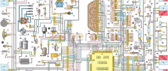
Electrical diagram of VAZ-2112
Designations: 1 – Headlight, 2 – Klaxon, 3 – Main radiator fan, 4 – Starter, 5 – Battery, 6 – Generator 2112, 7 – Gearbox limit switch (reverse), 8 – Actuator in the front passenger door, 9 – Power window enable relay, 10 – Starter relay, 11 – Heater fan, 12 – Electric heater partition drive, 13 – Main pump, 14 – Washer reservoir sensor, 15 – Driver’s door actuator, 16 – Front passenger window selector, 17 – Unlock button fifth door, 18 – Heater fan resistance unit, 19 – Main wiper motor, 20 – Driver’s window lift selector, 21 – Front passenger’s window lift motor, 22 – Central locking, 23 – Exterior light switch, 24 – Brake fluid leakage sensor, 25 – Pump additional, 26 – Driver's window lift motor, 27 – PTF on indicator, 28 – PTF switch, 29 – Dashboard, 30 – Heated glass on indicator, 31 – Heated glass switch, 32 – Steering column selector switch, 33 – PTF relay, 34 – Ignition switch, 35 – Main fuse block, 36 – Illumination of heater controls, 37 – Hazard warning button, 38 – Heater control controller, 39 – Glove compartment lighting, 40 – Glove compartment lid end cap, 41 – Cigarette lighter, 42 – BSK – display unit, 43 – Ashtray illumination, 44 – 12V socket, 45 – Instrument lighting switch, 46 – Actuator in the right rear door, 47 – Right rear passenger window selector, 48 – Clock, 49 – Right rear passenger window motor, 50 – Brake limit switch (closed – pedal is pressed), 51 – Left rear passenger window motor, 52 – Left rear passenger window selector, 53 – Actuator in the left rear door, 54 – Turn signal, 55 – Handbrake limit switch (closed – handbrake on), 56 – Rear wiper motor , 57 – Navigator's lamp, 58 – Interior lamp, 59 – Temperature sensor in the heater, 60 – Limit switch for the open front door, 61 – Limit switch for the open rear door, 62 – Trunk light, 63 – Rear optics (on the body), 64 – Rear optics (on the fifth door), 65 – License plate illumination.
The letters indicate the terminals to which it is connected: A – Front speaker on the right, B – Radio, C – Injector harness, D – ESD diagnostic connector, D – Front left speaker, E – Diagnostic connector for the heater controller, G – Rear right speaker, W – Rear left speaker, I – BC connector, K – glass heater thread, L – fifth door actuator, M – Additional brake light.
Wiring diagram VAZ-2112 injector 16 valves - full view
Replacing the wiring harness in the rear of the car
The vehicle's owner's manual warns that adverse weather conditions may adversely affect the vehicle's electrical components. And connectors and electrical cables are among the first to suffer.
Girls in revealing dresses are a favorite “bait” of scammers
And since the price of spare parts is low, the car owner can replace:
- Rolled terminal block;
- Broken insulating wire;
- Units and accessories are approved for installation on other models of the VAZ family.
Wiring diagram for VAZ 2112 - wiring and connectors for the rear of the car
Tip: This requires a VAZ 2112 wiring diagram with decoding in order to clearly understand which electrical circuit is responsible for what and controls what.
Rear Harness Terminal Blocks
Let's take a closer look at the diagram above:
- general wiring terminal block for connecting wiring coming from the instrument panel (in diagram No. 1);
- terminal block for wiring for connection to the electrical wiring of the instrument panel of cars in the “standard” configuration and for connection to the wiring of the side doors for cars in the “luxury” configuration (in diagram No. 2);
- rear wiring terminal block for connection to instrument panel wiring (No. 3);
- two 4-pole terminal blocks (for modifications 2112-3724558-10 16 valves). Marked on the diagram under No. 4 and item 5;
- side direction indicators (under No. 6 - left), under No. 7 - right);
- power supply for the individual lighting lamp (number 8 in the diagram);
- power supply unit for general interior lighting (item 9);
- handbrake sensor connector (No. 11);
- rear lights (in the diagram No. 11 - on the left, No. 12 - on the right);
- connector for the temperature sensor in the cabin (No. 13 in the diagram);
- connector for connecting 4 internal switches for the light ceiling (in the diagram nos. 14,15,16 and 17);
- trunk light connector (No. 18);
- mounting unit for backup power (in diagram No. 19). Can be used as a connector to connect to the side door harness;
- block for connecting the license plate lighting wiring harness (no. 20 in the diagram);
- The wiring grounding points are indicated in the diagram as A and A1.
Wiring an additional wiring harness for VAZ 2112
Individual wiring parts must also be replaced with your own hands. In particular, additional wiring in the trunk of the car (pictured below).
Connects to the network:
- rear window heating system;
- electric rear wiper gear;
- additional brake light;
- trunk lock motor.
Connection diagram for VAZ 2112: lighting and electrical equipment of the trunk
Electrical wiring VAZ 2112 this wiring has the following designations:
- via terminal block n. 1, the harness is connected to the main harness of the car. Includes 4 wires: red, yellow-blue, white-blue and pink-black;
- it is similar in functionality and there is no block. 2. Uses wires: green, white, black and red;
- terminal no. 3 is responsible for operating the electric motor unit and switching the rear wiper. The contacts are powered by 4 wires: black, pink-black, yellow-blue and white-blue;
- to connect the rear lights, the terminal blocks specified in paragraphs 4 and 5 are used;
- terminal no. 6 turns on the trunk lock motor. Wires: black and white;
- terminal block no. 7 is responsible for connecting the heated rear window (two red wires);
- The additional brake light is powered from terminal block No. 8 (black and red wires).
VAZ-21124 engine control circuit
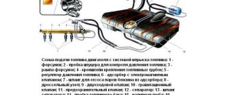
Connection diagram of the VAZ-21124 engine control system with distributed fuel injection to Euro-2 emission standards (controller M7.9.7): 1 - ignition coils; 2 — nozzles; 3 - controller; 4 - main relay; 5 - fuse connected to the main relay; 6 — cooling system electric fan relay; 7 - fuse connected to the cooling system electric fan relay; 8 - electric fuel pump relay; 9 - fuse connected to the electric fuel pump relay; 10 — mass flow and air temperature sensor; 11 — throttle position sensor; 12 — coolant temperature sensor; 13 — solenoid valve for purge of the adsorber; 14 — oxygen sensor; 15 — knock sensor; 16 — crankshaft position sensor; 17 — idle speed regulator; 18 — immobilizer control unit; 19 — immobilizer status indicator; 20 - phase sensor; 21 — vehicle speed sensor; 22 — electric fuel pump module with fuel level sensor; 23 — oil pressure warning lamp sensor; 24 — coolant temperature indicator sensor; A - block connected to the wiring harness of the ABS cabin group; B — diagnostic block; B - block connected to the air conditioner wiring harness; G - to the “+” terminal of the battery; D — to the side door wiring harness block; E - block connected to the instrument panel wiring harness; G1, G2 - grounding points; I - the order of conditional numbering of plugs in the block of the immobilizer control unit; II - the order of conditional numbering of contacts in the diagnostic block.
Connection diagram of the VAZ-21124 engine control system with distributed fuel injection under Euro-3 toxicity standards (controller M7.9.7): 1 - ignition coils; 2 — nozzles; 3 - controller; 4 - main relay; 5 - fuse connected to the main relay; 6 — cooling system electric fan relay; 7 - fuse connected to the cooling system electric fan relay; 8 - electric fuel pump relay; 9 - fuse connected to the electric fuel pump relay; 10 — mass flow and air temperature sensor; 11 — rough road sensor; 12 — throttle position sensor; 13 — coolant temperature sensor; 14 — idle speed regulator; 15 — control oxygen sensor; 16 — diagnostic oxygen sensor; 17 — solenoid valve for purge of the adsorber; 18 — knock sensor; 19 — crankshaft position sensor; 20 — immobilizer control unit; 21 — immobilizer status indicator; 22 - phase sensor; 23 — vehicle speed sensor; 24 — electric fuel pump module with fuel level sensor; 25 — oil pressure warning lamp sensor; 26 — coolant temperature indicator sensor; A - block connected to the wiring harness of the ABS cabin group; B — diagnostic block; B - block connected to the air conditioner wiring harness; G - to the “+” terminal of the battery; D — to the side door wiring harness block; E - block connected to the instrument panel wiring harness; G1, G2 - grounding points; I - the order of conditional numbering of plugs in the block of the immobilizer control unit; II - the order of conditional numbering of contacts in the diagnostic block.
How does the controller monitor the operation of the injector?
When determining the specific position and opening time of the injector design, the specific volume of fuel entering the valves of the VAZ-2110 cylinder is determined. At the same time, thanks to special sensors installed on the motor, the on-board computer records specific values and transmits them to the controller.
Subsequently, the controller, based on the information coming from the on-board computer, makes a decision on the position and duration of opening of the injector damper. If the controller malfunctions, the injectors will not be adjusted correctly, and the engine may stall while driving.
Tip: when starting the engine, the injector controller operates in asynchronous mode until the engine reaches a certain number of revolutions. That is why, after replacing the silent blocks of the front control arms on a VAZ-2110, you should warm up the car for 10-15 minutes.
VAZ-2112 diagram
The VAZ-2112 car was produced at AvtoVAZ from 1998 to 2009, in Ukraine from 2009 to 2014. The following are color wiring diagrams (injector and carburetor) with a description of all elements for various modifications. The information is intended for self-repair of cars. Electrical circuits are divided into several blocks for ease of viewing via a computer or smartphone; there are also circuits in the form of a single picture with a description of the elements - for printing on a printer in one sheet.
To diagnose and repair yourself, first look to see if everything is okay with the generator. Is it put on well and does not sag? This procedure must be done with all versions of the fuel system, both carburetor and injection. We check the fuses according to the electrical diagram. The reverse side of the safety block cover will also be of great help. There are clues there that the diagram will help you decipher. Replace the burnt out element and try to start the car again. You need to check whether the battery terminals are tightly connected and whether they are oxidized. Is the wire going from the battery to the generator and to the starter damaged?
Modifications of the VAZ-2112 car
VAZ-21120. Modification with a 16-valve injection engine with a volume of 1.5 liters and a power of 93 horsepower. 14-inch wheels were installed on the car. This modification has a problem with valves bending when the timing belt breaks. The problem can be solved by increasing the depth of the grooves in the piston bottoms.
VAZ-21121. The car was equipped with a VAZ-21114 8-valve injection engine with a volume of 1.6 liters and a power of 81 horsepower.
VAZ-21122. Budget modification with an 8-valve injection engine VAZ-2111. The car was produced without electric windows, the wheels were 13 inches in size, and the brakes were unventilated from a VAZ-2108 car.
VAZ-21123 Coupe. Three-door, five-seater hatchback. The only two doors for entering the car are 200 millimeters wider than those of the five-door hatchback, and they are mounted on new, durable hinges. The rear arches of the car have become wider. The engine was installed with a 16-valve injection engine with a volume of 1.6 liters and a power of 90 horsepower. The car was produced from 2002 to 2006 in small quantities, the reason for this was the high cost of the car.
VAZ-21124. Modification with a 16-valve injection engine VAZ-21124 with a volume of 1.6 liters. Produced from 2004 to 2008. For this type of engine, the problem with valve bending was solved. To do this, the depth of the grooves in the piston heads was increased (up to 6.5 mm). In addition, the design of the cylinder block was changed to achieve a working volume of 1.6 liters, for which its height was increased by 2.3 mm, and the radius of the crankshaft was increased by 2.3 mm accordingly. There were also a number of other minor changes.
VAZ-21128. The luxury version of the car, produced by Super-auto JSC, was equipped with a 16-valve VAZ-21128 engine with a volume of 1.8 liters and a power of 105 horsepower.
VAZ-2112-37. A racing modification of the VAZ-2112, prepared for the “ring” in the Lada Cup qualifying group. The car was equipped with a 1.5-liter VAZ-2112 engine with a power of 100 horsepower. The racing car was equipped with a safety cage, an external aerodynamic kit and a front extension of the strut support cups.
Common faults
As you can see, in general, a 16-valve engine is a rather complex system. Accordingly, there are also enough breakdowns in its operation; all of them can be divided into several groups. For example, if you have suspicions about the functionality of the spark plugs, and they turned out to be working, then you need to check the operation of the ignition coil and high-voltage cables. As practice shows, breakdowns in the wires can also lead to incorrect operation of the ignition system. Failure of one or another element of the electrical network can be a consequence of either a breakdown of the device itself or a failure of the generator unit or battery.
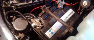
Most often, car owners are faced with the problem of battery failure, so let’s look at the main malfunctions characteristic of this device:
- a short circuit has occurred between the electrodes of the device;
- damage to the plates located inside;
- the appearance of cracks and other mechanical damage on the battery case, as well as shedding of the plates, which can lead to leakage of electrolyte;
- oxidation of the battery terminals, this problem can be solved by stripping.
All these faults ultimately lead to battery discharge. If we talk about the reasons that caused these problems, then most likely they all lie in incorrect operation, of course, if the battery life is high and has not yet expired. Much less often, the malfunction lies in a manufacturing defect, but this happens infrequently.
To prevent malfunctions in the operation of the battery, the following rules should be taken into account during operation:
- Firstly, the device must be securely fixed at the landing site. If the battery is not secured securely, this can lead to constant vibration, which can subsequently cause cracks in the case.
- Operation of the car and, accordingly, the use of the electrical network is allowed only when using a working generator. If the alternator is faulty or its belt tension is weak, it will ultimately lead to battery discharge.
- If the contact at the device terminal is poor, this can lead to its oxidation and destruction.
- Cranking the starter for a long time when trying to start the engine also contributes to battery discharge. This problem especially often manifests itself in cold weather, when the battery electrolytes are less mobile, and the driver has to turn the starter longer to start it (the author of the video is Vyacheslav Kravchenko).
Repairing a VAZ 2111. The would-be electricians almost burned the car.
Depending on the type and manufacturer, the battery life can range from three to five years. However, the service life may be shorter if the battery is used intensively and in harsh conditions. One way or another, the consequence of battery discharge is always the same - the device will not be able to crank the starter to start the engine, as well as power the devices and equipment of the car as a whole. If the diagnostics show that the battery is working normally, the cause of the malfunction may lie in the performance of the generator.
Its design as a whole is more complex; accordingly, this unit has a lot of faults:
- erasing of brushes due to their wear;
- voltage regulator relay failure;
- failure of the diode bridge;
- bearing wear, which is accompanied by a hum when the generator operates;
- wear of slip rings;
- damage or wear of pulley teeth;
- short circuit in the stator winding;
- damage to the charging circuit wiring;
- broken or worn alternator belt.
Malfunctions in the operation of the unit can be determined by diagnostics using a multimeter. As for repairs, you can do it yourself. We have previously described the procedure for repairing a generator using the VAZ 2114 model as an example in this article; in the case of the VAZ 2111 it looks similar.
As for other malfunctions in the operation of the electrical circuit, there may be several reasons:
- failure of the device itself;
- fuse blown caused by a short circuit (before replacing the fuse, it is necessary to determine the cause of the short circuit);
- electrical circuit breakage, the problem is solved by replacing the wire;
- oxidation of contacts on device terminals (video author - Ramanych channel).
We treat wiring VAZ 2110 16V
Installation of fog lights
Car owners can independently equip their car with fog lights. For ease of installation, you can watch videos from forums where masters share their experience of such work.
VAZ 2112 Wiring of fog lights (Luxury degree)
Conclusions: in fact, replacing old wiring in the rear of the car is much easier than in the engine compartment or inside the cabin. And the diagrams proposed in the article will help you figure it out faster and prevent mistakes.