Any car will last you for the rest of your life if you drive hard enough
Injection power units on rear-wheel drive classics, a prominent example of which is the VAZ 2107-20, have had a serious impact on the domestic passenger car fleet. But not all car owners initially appreciated the advantages of the injection system in comparison with a traditional carburetor, fearing more difficulties in the operation of electronic components. Is this really so, we will try to figure it out within the framework of this article.
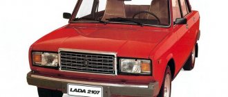
Representative of the rear-wheel drive VAZ family, which received an injection system
What's new
The main innovation was the replacement of the mechanical functions of the ignition system and preparation of the air-fuel mixture with electronic devices, which are more accurate and efficient. The wiring diagrams of the VAZ 2112 and the Samara family also underwent a similar modernization. Accordingly, the wiring of the VAZ 2107 to the injector received differences from the carburetor version.
Under the hood of the VAZ 2107-20, the absence of a carburetor and distributor is immediately striking
ECM functions
The electronic engine control system (abbr. ECM) took on the following operating parameters of the power unit:
- Controlling the amount of air and gasoline entering the car engine cylinders,
- crankshaft speed
- Spark plug control;
- Adjustment of ignition timing in all operating modes;
- Turning the electric fuel pump on and off,
- Control of the electric fan of the engine cooling system.
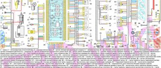
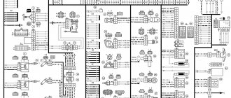
The photo below shows a VAZ 2107 wiring diagram for an injector with an M1.5.4N ECM and a January-5.1.3 controller
Injection system VAZ 2107
Electrical diagram
The classic 2107 wiring on cars with an injection system has also undergone changes. In particular, under-hood elements equipped with connectors for sensors and electronic devices have appeared.
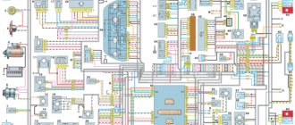
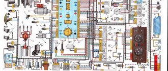
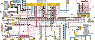
Electrical diagram of VAZ 2107 with carburetor
For reference: The developers of Moskvich 2141 followed a similar path. True, they had a more global problem - the lack of their own engine.
Explanation for the electrical diagram of the carburetor VAZ 2107
For reference: The photo below shows the electrical wiring of a VAZ 2107 to an injector with catalog numbers. The differences from carburetor kits are in the engine compartment harnesses.
When converting the engine to an injection system, you should also purchase new wiring
Practical advice
The operation of an injection power unit, and in particular the maintenance of its electronic components, is fundamentally different from carburetor engine systems.
Owners of converted cars must learn a few basic rules:
- Before dismantling the injection control system components, be sure to disconnect the negative cable from the battery terminal;
Working with car wiring requires care and precision.
- Do not start the engine if the terminals of the wires on the battery have poor contact. Be sure to check how tightly they are tightened;
- Do not disconnect the battery while the vehicle engine is running. This is guaranteed to lead to failure of the ECU;
- Monitor the ECU temperature. It is not allowed to overheat (65°C when the car is running and above 80°C, for example when drying in a paint booth). If such a process is unavoidable, remove the ECU from the vehicle for the duration of the work;
- It is also necessary to remove the ECU or disconnect it from the vehicle’s on-board system when carrying out welding work on body parts.
Differences in work
Advantages
So, what are the benefits received by the car owner whose car has injection installed:
- There is less chance of stalling when starting from a standstill - the electronics react more flexibly to the operation of the gas pedal, allowing you to move off more confidently from idle;
The engine compartment wiring harness of the VAZ 2107-20 has different connectors
- Easy engine starting - there is no need to manually operate the choke knob;
- Reduced warm-up time for a cold engine - the electronic system optimizes the minimum stable speed. You can start moving after starting, without fear of jerks and dips typical of a carburetor;
- Reduce routine maintenance of electrical equipment . In particular, there is no need to constantly adjust the gap in the breaker contacts;
For reference: Other domestic car factories also modernized electrical equipment, in particular the ignition system - see the publication on the UAZ 31514 wiring diagram.
- Reduced adjustment work on the carburetor - electronics can reduce fuel consumption and make engine operation more environmentally friendly.
In the video you can see the stable start of the VAZ 2107 injection engine.
Flaws
The injection system also has some flaws, in particular:
- Without a diagnostic tool, it is quite difficult to identify a malfunction in the engine management system;
- Standard wiring 2107 does not allow troubleshooting using a warning lamp;
- The factory instructions most often instruct you to contact a service center for diagnostics. However, the price of such a service is not always justified for the car owner.
In the photo - diagnostics of the oxygen sensor of the VAZ 2107
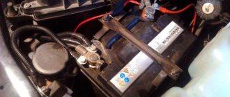
The VAZ 2105 battery has boiled - what to do?
There are several reasons why batteries boil. Let's consider them in order of importance:
- Recharging the battery
- Short circuit of cans
- Sulfation of plates
- Electrical system overload
- Battery polarity reversal
If the battery boils on your car while driving, you must immediately take the following steps:
- turn off the engine;
- open the hood to provide air flow; if the battery has a jacket, remove it; Allow the battery to cool to a temperature below 40 degrees Celsius (easily determined by touching it with your hand); close the hood, start the car and drive to the nearest gas station;
- purchase distilled water and top up to the required electrolyte level;
- if the battery is maintenance-free, topping up can be done through the gas outlet;
- if the repair kit contains a multimeter, measure the voltage on the battery with the engine running; if the voltage exceeds 15 Volts, disconnect the thick wire of the generator, carefully insulating it and securing it to the nearest body element;
- Continue driving to the parking or repair site, turning off, if possible, all additional comfort devices (stove, car radio, air conditioning and others).
Electrical diagram VAZ-2107 carburetor
Electrical diagram of VAZ 2107, 21074 produced in 1988-2001 with generator 37.3701
- block headlights
- side direction indicators
- accumulator battery
- starter relay
- carburetor electro-pneumatic valve
- carburetor microswitch
- generator 37.3701
- gearmotors for headlight cleaners *
- Fan motor switch sensor
- engine cooling fan motor
- sound signals
- distributor
- spark plug
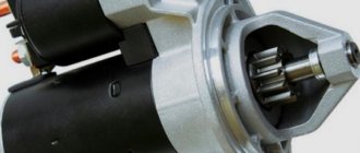
- starter
- coolant temperature gauge sensor
- engine compartment lamp
- low oil pressure warning sensor
- low brake fluid level indicator sensor
- windshield wiper motor
- carburetor electro-pneumatic valve control unit
- ignition coil
- headlight washer pump motor *
- windshield washer pump motor
- mounting block
- windshield wiper relay
- hazard warning and direction indicator relay
- brake light switch
- reverse light switch
- ignition relay
- ignition switch
- three lever switch
- hazard switch
- socket for portable lamp**
- heater fan switch
- additional resistor for the electric motor of the heater (stove)
- rear window heating indicator lamp
- low brake fluid level warning lamp
- signaling unit
- heater fan electric motor
- glove compartment lamp
- light switches on the front door pillars
- switches for warning lights of open front doors ***
- front door open warning lights ***
- connection block
- cigarette lighter
- watch
- instrument light switch
- diode for checking the serviceability of the low brake fluid level indicator lamp
- fuel level indicator
- fuel reserve indicator lamp
- speedometer
- turn signal indicator lamp
- carburetor choke indicator lamp
- battery charge indicator lamp
- carburetor choke warning switch
- instrument cluster
- econometrician
- light switches on the rear door pillars
- coolant temperature gauge
- tachometer
- parking brake indicator lamp ("handbrake")
- low oil pressure warning lamp
- high beam indicator lamp
- indicator lamp for turning on external lighting
- voltmeter
- parking brake indicator switch ("handbrake")
- outdoor light switch
- rear window heating switch with backlight
- rear fog light switch with on/off indicator *
- fog light circuit fuse
- lampshade ****
- tail lights
- level indicator and fuel reserve sensor
- connectors for connecting to the rear window heating element *
- license plate lights 2107
Wiring diagram VAZ-2107 carburetor - full view:
Repair of VAZ 2105 generator
Having determined that the generator needs repair, it must first be removed from the car. To perform the operation you will need the following tools:
- keys for 17 and 19;
- heads for 10, 17 and 19;
- ratchet handle and knob;
- extension with cardan joint.
How to remove the generator
We dismantle the unit in the following order:
- Remove the negative terminal from the battery and disconnect the wiring from the generator.
- We unscrew the nut of the upper fastening of the unit with a 17 socket and a wrench, loosen the belt and remove it. During assembly, if necessary, we change the belt drive.
- We go down under the front of the car and rip off the bottom nut, then unscrew it with a ratchet.
- We knock out the bolt with a hammer, placing a wooden block on it, which will prevent damage to the thread.
- We take out the fasteners.
- We take the generator down and take it out.
- After repair work, install the device in the reverse order.
Generator disassembly and repair
To disassemble the mechanism you will need the following list of tools:
- wrench and socket 10 with extension;
- hammer and adapter made of soft metal;
- bearing puller;
- crosshead screwdriver.
The operation consists of the following steps:
- Using a Phillips screwdriver, unscrew the fastening of the relay-regulator to the housing.
- We take out the regulator along with the brushes.
- If the coals are in poor condition, we change them when assembling the unit.
- We stop the armature from turning with a screwdriver, and with a 19mm wrench we unscrew the nut holding the generator pulley.
- Remove the washer and pulley, consisting of two parts, from the rotor shaft.
- We remove another washer and impeller.
- Remove the key and washer.
- Unscrew the nut securing the capacitor terminal.
- We remove the contact and unscrew the capacitor mount, dismantling the part from the generator.
- To ensure that the parts of the generator housing fall into place during installation, we mark their relative positions with paint or a sharp object.
- Use a 10mm socket to unscrew the fastenings of the housing elements.
- We remove the fasteners.
- We dismantle the front part of the generator.
- If the bearing needs to be replaced, unscrew the nuts that hold the plate in place. Typically, bearing wear manifests itself in the form of play and noise during rotation.
- We remove the plate itself.
- We squeeze out the old ball bearing and press in a new one with a suitable attachment, for example, a head or a piece of pipe.
- We remove the thrust ring from the armature shaft so as not to lose it.
- We screw the nut onto the shaft and, tightening it in a vice, pull off the rear part of the housing along with the stator coils.
- If the anchor comes out with difficulty, tap the end part with a hammer through a drift.
- We remove the rotor from the stator.
- Using a puller, remove the bearing. To press in a new one, we use a suitable attachment so that the force is transferred to the inner race.
- We unscrew the fastening of the coil contacts to the diode bridge.
- Using a screwdriver, we remove the stator windings.
- Remove the rectifier block. If during diagnostics it was discovered that one or more diodes have failed, we replace the plate with rectifiers.
- Remove the bolt from the diode bridge.
- From the rear of the generator housing, remove the bolts securing the coil terminals and the diode bridge.
Mounting block connection diagram
P1 — relay for turning on the heated rear window; P2 - relay for turning on the headlight cleaners and washer; P3 - relay for turning on sound signals; P4 - relay for switching on the electric motor of the engine cooling system fan; P5 - headlight high beam relay; P6 - low beam headlight relay; A - the order of conditional numbering of plugs in the mounting block blocks. The outer number with the letter “Ш” in the plug designation is the block number, and the inner number is the conventional number of the plug.
Injector maintenance
Since the injection power system is quite complex, during the operation of the car there is a need to eliminate failures and failures. You can service the car yourself if you have a detailed diagram. In particular, engine management systems:
To troubleshoot you need:
- availability of electronic testers (their price is low - you should definitely buy them);
- adapters through which the tester is connected to the diagnostic connector.
By comparing the measurement results with operating parameters, you can easily identify an electrical circuit operating with deviations. And only then, when analyzing it, detect a non-working device: sensor or wiring.
Schemes of individual blocks of the seven
Power supply system
Power plant starting system
1 - starter; 2 - relay; 3 — ignition switch; 4 - battery
Ignition system
1 - generator; 2 — ignition switch; 3 - distributor; 4 - breaker; 5 — candles; 6 - coil; 7 - battery
Contactless ignition system
External and internal lighting
Windshield wipers and washers
1 — electric motors of the windshield wiper; 2 — washer motor; 3 — mounting block; 4 — ignition switch; 5 - washer switch
Cooling Fan
1 — fan electric motor; 2 - sensor; 3 — mounting block; 4 - ignition relay; 5 - ignition switch.
Carburetor sevens
In these cars, the control system for turning on the electric fan is very simple. It can even be called analog. The entire circuit consists of the simplest form of the following elements:
- Electric fan motor.
- Power sensor.
- Wiring.
That's it, there is nothing else, you need to look for breakdowns only in these parts of the structure. In 70% of cases the sensor fails, in 5% the electric fan fails, in 20% the electrical wiring is to blame.
Advice!
To diagnose a car, I recommend using a fairly cheap solution: install it once and use it always.
But some cars use a slightly more advanced circuit, which includes an electromagnetic relay. With its help, it is possible to remove high currents from the sensor. This increases the resource of the device.
Some drivers who are not used to trusting automation install a regular button parallel to the sensor (and sometimes instead of it). Such a scheme has a right to exist, but the driver himself must be extremely careful in order to notice the temperature rise in time and turn on the electric fan.
Wires for connecting electrical appliances
| Connection type | Section, mm 2 | Insulation color |
| Negative terminal of the battery - vehicle ground (body, engine) | 16 | Black |
| Starter positive terminal - battery | 16 | Red |
| Positive contact of the generator - plus battery | 6 | Black |
| Generator - black connector | 6 | Black |
| Terminal on the generator “30” – white MB block | 4 | Pink |
| Starter connector “50” – starter relay | 4 | Red |
| Starter Start Relay - Black Connector | 4 | Brown |
| Ignition switch relay - black connector | 4 | Blue |
| Ignition switch output “50” – blue connector | 4 | Red |
| Ignition switch connector “30” – green connector | 4 | Pink |
| Right headlight plug - ground | 2,5 | Black |
| Left headlight plug - blue connector | 2,5 | Green, gray |
| Generator output “15” – yellow connector | 2,5 | Orange |
| Right headlight connector - ground | 2,5 | Black |
| Left headlight connector - white connector | 2,5 | Green |
| Radiator fan - ground | 2,5 | Black |
| Radiator Fan - Red Connector | 2,5 | Blue |
| Ignition switch output “30/1” – ignition switch relay | 2,5 | Brown |
| Ignition switch contact “15” – single-pin connector | 2,5 | Blue |
| Right headlight - black connector | 2,5 | Grey |
| Ignition switch connector “INT” – black connector | 2,5 | Black |
| Six-pin block of the steering column switch - “ground” | 2,5 | Black |
| Two-pin block of the steering column switch - glove box illumination lamp | 1,5 | Black |
| Glove compartment light - cigarette lighter | 1,5 | Black |
| Cigarette lighter - blue block connector | 1,5 | Blue, red |
| Rear window defroster - white connector | 1,5 | Grey |
How to replace fuses
It is important to know that you cannot install a thick wire instead of a blown fuse; this can cause a fire in the wiring, or even the car as a whole.
Such a need may arise when the fuse link burns out due to overloads or short circuits in the circuits. The old modification blocks have cylindrical protective elements. Place them in one row in order from left to right. The burnt-out element is carefully removed from the spring-loaded holders, but this should be done carefully.
The fuse and holders may become very hot. Before installing a working fuse link, you should make sure that there are no short circuits in the protected circuits. Otherwise, the protection will burn out very often. You should also lightly tighten the spring contacts; if there are traces of oxidation on them, they need to be removed.
New fuse blocks are equipped with blade protective elements, which are not so easy to remove. For this purpose, there are special tweezers inside the case. If this does not help to remove the faulty fuse link, you can use small pliers.
Car wiring diagram
1 – radiator fan drive motor; 2 – relay and fuse block (mounting block); idle speed sensor; 4 – engine control unit; 5 – potentiometer; 6 – set of spark plugs; 7 – ignition control unit; 8 – electronic crankshaft sensor; 9 – electric fuel pump; 10 – tachometer 2107; 11 – lamp for monitoring the health of electronic systems; 12 – ignition system control relay; 13 – speed sensor; 14 – diagnostic connector; 15 – set of injectors; 16 – adsorber solenoid valve; 17, 18, 19 – fuse block protecting the injection system circuits; 21 – electronic fuel pump control relay; 22 – electronic relay for controlling the intake pipe heating system; 23 – intake pipe heating system; 24 – fuse protecting the heater circuit; 25 – electronic oxygen level sensor; 26 – cooling system temperature control sensor; 27 – electronic air damper sensor; 28 – air temperature sensor; 29 – pressure control sensor.
New power system
To understand why so many different electrical equipment are installed on the car, and what the electrical wiring unites, you need to understand the principle of operation of the new power system.
Advice: For general development, it’s a good idea to watch a video on the Internet that clearly explains the difference in the operation of these systems.
The main difference between an injection system and a carburetor system is as follows:
- The electric fuel pump constantly increases the pressure in the fuel line (in the carburetor version there is no pressure, and the pump itself is mechanical);
- The air-fuel mixture is formed directly in the cylinder (injection system), whereas on the “classic” it is formed in the carburetor;
- Electric injectors are responsible for injecting fuel into the cylinders (nozzles in the carburetor, and from there the air-fuel mixture enters the intake manifold and then into the cylinders);
- The timing of injection is determined by the ECM (in the carburetor, fuel is sucked in when the intake valve opens).
Differences in electrical wiring
The platform for creating the VAZ 21074 car was the VAZ 2107 model. And although the same 1.6-liter engine was installed on the “seventy-four,” the carburetor was replaced with an injector.
Fuse and relay diagram 2107
On newer “sevens” a block with 17 fuses and 6 relays is installed. VAZ 2107 fuses on the “new” unit protect the following electrical circuits and devices:
- Reversing lamps, heater fan, rear window defroster warning lamp and relay, rear wiper motor and rear washer pump.
- Electric motor for front wipers.
- Reserve socket.
- Reserve socket.
- Power supply for heated rear window.
- Clock, cigarette lighter, power socket “carrying”.
- Signal and radiator fan.
- Turn signal lamps in emergency mode.
- “Fog lights” and a relay that regulates the voltage of the on-board network.
- Instrument panel lamps.
- Brake light bulbs.
- Right high beam headlight.
- Left high beam headlight, high beam warning lamp.
- Side lights (rear right, front left), license plate and engine compartment lighting.
- Side lights (rear left, front right), glove compartment and cigarette lighter lamps.
- Low beam (right lamp).
- Low beam (left lamp).
The block relays perform the following functions:
- Heated rear window relay.
- Headlight cleaner and washer relay.
- Signal relay.
- Cooling system electric fan relay.
- High beam relay.
- Low beam relay.
The fuse block of the VAZ 2107 (injector) is no different from the block on the carburetor “seven”. Injection models are simply equipped with an additional relay and fuse box installed in the cabin under the glove compartment. The block includes three relays - the “main” relay, the fuel pump relay and the fan relay.
Replacement of electrical wiring of VAZ 2104
If there is a failure in the power supply to electrical equipment, you should first check the integrity of the electrical circuit. To do this you need:
- De-energize the area being tested by disconnecting the negative terminal of the battery or the corresponding fuse.
- Connect the contacts of the multimeter to the ends of the problem section of the circuit, and one of the probes to ground.
- If there are no readings on the multimeter display, there is a break in the circuit.
- The wiring is replaced with a new one.
Selection of wires and replacement of wiring is carried out according to the power supply diagram of the VAZ 2104. In this case, standard components or components from another model with suitable characteristics are used. To replace the wiring, the front part of the cabin is disassembled. Wires of insufficient length are extended, and connections are soldered and insulated. It is almost impossible to completely replace the electrical wiring of a VAZ 2104 with your own hands. If such a situation arises, it is better to contact a car service.
Video: replacing wiring, fuses and relays of classic VAZ models
To replace the wiring, the front part of the cabin is disassembled. Wires of insufficient length are extended, and connections are soldered and insulated.
Video: replacing electrical wiring in the cabin and under the hood
It is almost impossible to completely replace the electrical wiring of a VAZ 2104 with your own hands. If such a situation arises, it is better to contact a car service.
Modifications of the VAZ-2107 car
VAZ-2107 . Basic version of the sedan, with an 8-valve carburetor VAZ-2103 engine, 1.5 liters.
VAZ-2107-20 . The same VAZ-2107, but with a 1.5-liter VAZ-2104 injection engine that meets the Euro-2 environmental standard.
VAZ-2107-71 . The car for the Chinese market was equipped with a VAZ-21034 engine, with a volume of 1.4 liters and a power of 66 horsepower, specially tuned for A-76 gasoline. The pistons were taken from a VAZ-2108.
VAZ-21070 . Modification of a car with an 8-valve, carburetor VAZ-2103 engine, volume 1.5 liters.
VAZ-21072 . Modification with an 8-valve carburetor VAZ-2105 engine, volume 1.3 liters.
VAZ-21073 . An export modification for the European market, which was equipped with a 1.7-liter injection engine with a capacity of 84 horsepower. The engine of this car had a catalytic converter that satisfied environmental protection requirements.
VAZ-21074 . Modification with an 8-valve, carburetor VAZ-2106 engine, volume 1.6 liters.
VAZ-21074-20 . Modification with a 1.6-liter VAZ-21067-10 injection engine, which complies with the Euro-2 environmental standard
VAZ-21074-30 . Like the previous model, but with a VAZ-21067-20 engine, which meets the Euro-3 environmental standard
VAZ-210740 . Modification produced in 2010, equipped with a VAZ-21067 injection engine with a catalyst. Engine capacity is 1.6 liters, power is 72.7 horsepower.
VAZ-21076 . Export modification with a VAZ-2103 carburetor engine.
VAZ-21077 . Export modification with right-hand drive for the UK market. The car was equipped with a VAZ-2105 carburetor engine with a volume of 1.3 liters.
VAZ-21078 . Another export modification for the UK, but with a 1.6-liter VAZ-2106 carburetor engine
VAZ-121079 . The modification, developed specifically for the needs of the Ministry of Internal Affairs and the KGB, was equipped with a powerful VAZ-413 rotary piston engine with a volume of 1.3 liters and a power of 140 horsepower.
VAZ-2107 ZNG . The car is equipped with an 8-valve, fuel-injected VAZ-21213 engine with a volume of 1.7 liters.
What generators can be installed on a VAZ 2105
The question of choosing a generator for a VAZ 2105 arises when the standard device is not capable of providing current to the consumers installed on the car. Today, many car owners equip their cars with powerful headlights, modern music and other devices that consume high current.
To equip your car with a more powerful source of electricity, you can install one of the following options:
- G-2107–3701010. The unit produces a current of 80 A and is quite capable of providing additional consumers with electricity;
- generator from VAZ 21214 with catalog number 9412.3701–03. The current produced by the device is 110 A. For installation, you will need to purchase additional fasteners (bracket, strip, bolts), as well as make minimal changes to the electrical part;
- product from VAZ 2110 for 80 A or higher current. For installation, a suitable mount is purchased.
One of the powerful options for generator sets that can be equipped with a VAZ 2105 is a device from a VAZ 2110
How does the controller monitor the operation of the injector?
When determining the specific position and opening time of the injector design, the specific volume of fuel entering the valves of the VAZ-2110 cylinder is determined. At the same time, thanks to special sensors installed on the motor, the on-board computer records specific values and transmits them to the controller.
Subsequently, the controller, based on the information coming from the on-board computer, makes a decision on the position and duration of opening of the injector damper. If the controller malfunctions, the injectors will not be adjusted correctly, and the engine may stall while driving.
Tip: when starting the engine, the injector controller operates in asynchronous mode until the engine reaches a certain number of revolutions. That is why, after replacing the silent blocks of the front control arms on a VAZ-2110, you should warm up the car for 10-15 minutes.
Checking the main relay in a Lada Samara car
The prices for such devices in car dealerships are minimal, but their importance cannot be denied, since they largely affect the performance of electrical equipment. F8 7.5 A.
The cost of these elements in stores is minimal, but they play a very important role and must always be in working order. The box is designed for three relays and three 15A fuses, and is covered with a plastic shield on top.
The exterior decoration was decorated with plastic elements, since metal ones were corroded by corrosion.
In the instrument panel wiring harness, the second ends of the white wires are brought together into one point, which is connected to the instrument lighting switch except for the white wire, from plug “4” of block “X2” of the mounting block 28 to the display block 83 of the on-board control system.
However, in general, the VAZ model remains the same - it is equipped with front-wheel drive and five doors.
Give preference to new models. Despite modernization, many motorists who are far from the domestic automobile industry are still confused and
Fuses do not protect only: the ignition circuit; electrical circuit for powering the generator and starter. How to check the ignition module, ignition coil and armored wires?!