Cars admin26.02.2020
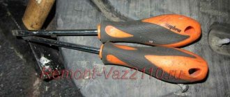
Hi all! I’ll tell you about a very useful modification that will be useful for owners of elderly VAZ 2110. Many ten-year-olds have encountered a problem when, in hot weather, a hot engine does not respond to the movement of the key. The starter does not turn and you have to go under the hood with a screwdriver and make a direct connection to the contacts. In the case when the starter is working (in my case it is completely new), the culprit for this trouble may be the contact group of the ignition switch. Over time, the contact group in the ignition switch wears out or the current collector contacts burn out. This problem is successfully solved by installing an additional unloading relay. By the way, such a relay is installed on many cars from the factory.
To install this relay we will need: 4-pin relay with a metal ear (30-40A); 80r Wires 1.5 sq. mm; about three meters -80r relay block - 1 piece; 20r Flat male connector - 1 piece; Flat female connector - 1 piece; Ring tips - 2 pcs. Electrical tape, heat shrink, corrugation.
Those people who have a VAZ 2110 have certainly encountered a situation where the starter did not turn after the key was turned, and some clicks are heard, which indicate that the retractor relay is working. In such a situation, the question immediately arises: where is the VAZ 2110 starter relay located and how to find it faster. This question is also relevant when tuning a VAZ 2111.
But we have interesting news for you: the VAZ 2110 simply does not have a starter relay. There is a solenoid relay, to which the positive contact is supplied from the ignition switch. The relay is installed on the starter, its size is 2 times smaller than that of the starter, and it is round in shape.
Next, we will highlight some popular malfunctions that usually arise in the VAZ 2110, related to the VAZ 2110 starter relay and the starter; by the way, a lot of things are used in the VAZ 2115, so by tuning this car, many problems can be avoided.
Basic starter malfunctions
The traction relay does not operate after the ignition key has been turned, and the armature does not rotate.
In this situation, it may be due to the following possible problems:
- the battery is broken or discharged, the solution to this problem is to buy a new battery or charge it;
- the positive contacts have oxidized - you just need to clean them;
- it happens that an interturn short circuit occurs on the winding of the traction relay - to correct this situation, you need to install a new relay;
- the circuit that powers the traction relay has broken - you need to check the wires for integrity, and whether they have become disconnected from the circuit?
- contacts “30” and “50” do not close - you just need to change the contact part of the ignition switch;
- The traction relay armature does not work well - you need to remove it and disassemble it, there may be a lubrication problem.
After turning the key, the starter does not start, the armature rotates slowly, and a click is heard in the traction relay.
This situation may arise due to previously similar situations:
- the battery is discharged or disconnected - you need to check and correct the situation;
- the winding of the traction relay is shorted or broken - you also just need to change the relay;
- the ends of the wires have seriously succumbed to oxidation - they need to be checked and cleaned, starting with the battery.
After turning the key, the starter armature spins, but the flywheel does not spin..
This situation arose due to the fact that:
- the freewheel is slipping - you need to diagnose the starter at the stand and replace the clutch if it is faulty;
- The gears on the gearbox are worn out - you just need to replace them.
The starter makes a lot of noise when the armature is spinning.
This problem arose because:
- The liners on the armature or drive shaft bearings have served their service life - you just need to replace the parts that have failed;
- the starter is not secured properly, and the cover could have broken - you just need to secure it or change it;
- the gears on the gearbox, flywheel crown or drive have failed - you just need to change them, or immediately replace the non-functioning parts entirely.
- the gear is constantly engaged with the flywheel; if the clutch on the shaft splines is stuck, it is possible that the armature of the traction relay is stuck - to solve this problem, you need to lubricate the splines with oil. And if the traction relay is stuck, then you need to either change it or use certain methods to get rid of the jam.
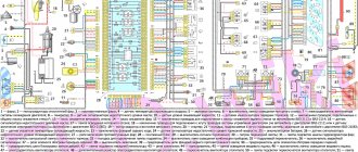
Wires of the ignition switch of a VAZ 2114 (2113, 2115) car
A block with wires of different colors is attached to the ignition switch (ignition switch) of the VAZ 2114 (2113, 2115) car.
Let's try to figure out which wire goes to what and which electrical circuits the ignition switch closes when the key is turned to different positions.
Wires of the ignition switch of a VAZ 2114 (2113, 2114) car
What electrical circuits are closed when the key is turned in the ignition switch of a VAZ 2114
Key position "0" - off
Contact “30” of the ignition switch is energized (terminal “7” of the lock wire block). Nothing is turned on (does not close).
VAZ 2110 starter relay: installation
And then a video on how to install an additional starter relay on a VAZ 2110:
Car : VAZ-2112. Asks : Petrov Viktor. The essence of the question : Where is the VAZ-2112 starter relay located?
Good afternoon My car stopped starting. I am the owner of a VAZ-2112, 16-valve engine. I start to start it, but it won’t start, and even the starter doesn’t turn at all. They told me to look at the starter relay first, but they didn’t tell me how to find it at all. Please tell me!
ELECTRICAL DIAGRAM OF ENGINE STARTING AND CHARGING SYSTEMS FOR DAEWOO MATIZ
Lada Priora Sedan Logbook Preparing for winter. Starter
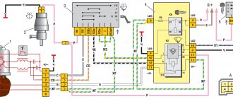
Power is supplied to the elements of this electrical circuit from the battery (1), through the ignition switch (2) to pins 2 and 5 from connector 102, having previously passed through fuses E15 and E16 with a rating of 30 Amps. From pin 3 of the ignition switch, through connector C202, power is supplied to the starter (4) and the starter relay (3) (Bendix). From pin 4, through fuses F10 and F14, 10 and 15 A, respectively, a charging control circuit with an indicator (5) passes through. Through connectors C101, C102 and C 202, the circuit is connected to contacts 1 and 2 of the generator voltage regulator (6). From the B+ contact of the generator, the charging current through the B+ contact on the starter travels through one wire to the positive terminal of the battery. Connections to the ground of the electrical circuit elements are marked: G104, G105 and B. For more details on the markings and color scheme of the circuit, see the designations and description “how to” read wiring diagrams for Daewoo Matiz.” To download the diagram, click on it with the left mouse button, and then, when it is highlighted, enlarge it and by clicking the right button, select “save as...”.
Wiring diagram for connecting the battery, starter and generator on Daewoo Matiz
| CONNECTOR NO. (CONTACT NO. AND COLOR) | CONNECTING HARNESS | CONNECTOR POSITION |
| C101 (pin 32, black) | Engine - fuse box in engine compartment | Fuse box in the engine compartment |
| C102 (pin 32, gray) | Instrument panel - engine compartment fuse box | Fuse box in the engine compartment |
| S202 (pin 23, white) | Engine - dashboard | Driver's left footwell |
| G104 | Accumulator battery | Under the battery |
| G105 | Accumulator battery | Near the starter |
Location of contact numbers and symbols:
Wiring of connectors of the ignition switch, starter and generator Daewoo Matiz 2005 onwards.
Location of connectors: 1 generator connector 2 ignition switch connector 3 starter (Bendix) relay connector 4 involved connectors in the dashboard
Drawings explaining the location of detachable connections in the engine compartment.
Daewoo Matiz_location of connectors and ground connections Fig. 1
Daewoo Matiz _location of connectors and ground connections Fig. 2
Finding the connectors under the panel:
Looking for a starter relay
If any devices on the car fail, then first of all you need to check the relay or fuse in the circuit. Therefore, as soon as after diagnosing them, it will be possible to draw conclusions about the problems as a whole.
As you know, on a VAZ-2112, even when the engine is not running, all devices are powered directly from the battery, and when it is started, the energy comes from the generator. And when the current in the circuit increases or there is a short circuit, the fuse simply blows, and a relay is provided for the most powerful devices.
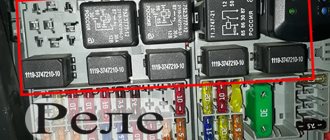
Photo of the starter relay in the fuse box
In order to get to the fuse and relay box in which the starter relay is installed, you need to find the cover on the underside of the dashboard. Then, press the locking button and fold it down.
The starter relay is marked with a red arrow
Replacing the old element with a new one must be done in the reverse order of removal.
Please note that in various vehicle configurations, additional relays can be installed on top of the unit, which are intended for certain groups of devices. But the starter relay is always installed second, on the right.
Some useful tips
To ensure that the solenoid relay lasts as long as possible, listen to these tips:
- If the battery is discharged, the starter turns slowly and its speed is not enough to start the engine, stop trying to start the car. This will not only cause the battery to become deeply discharged, but also damage the starter relay.
- When starting the engine, do not turn on the starter for more than 15 seconds. This will lead to an overload in its circuit, due to which the relay contacts may burn out, its windings and the starter windings may burn out.
- When choosing a replacement solenoid relay, do not buy cheap products. It is better to give preference to parts from well-known manufacturers, and buy them only in specialized stores.
Lada 2110 PhiX › Logbook › Additional, starter unloading relay VAZ 2110
Hi all! I’ll tell you about a very useful modification that will be useful for owners of elderly VAZ 2110. Many ten-year-olds have encountered a problem when, in hot weather, a hot engine does not respond to the movement of the key. The starter does not turn and you have to go under the hood with a screwdriver and make a direct connection to the contacts. In the case when the starter is working (in my case it is completely new), the culprit for this trouble may be the contact group of the ignition switch. Over time, the contact group in the ignition switch wears out or the current collector contacts burn out. This problem is successfully solved by installing an additional unloading relay. By the way, such a relay is installed on many cars from the factory.
To install this relay we will need: 4-pin relay with a metal ear (30-40A); 80r Wires 1.5 sq. mm; about three meters -80r relay block - 1 piece; 20r Flat male connector - 1 piece; Flat female connector - 1 piece; Ring tips - 2 pcs. Electrical tape, heat shrink, corrugation.
Let's put this whole thing together according to the following scheme.
The relay needs to be protected from moisture, for this I used thick heat shrink, in which I completely covered the relay block.
After assembly, I check the relay by connecting it to the LBP.
Pay attention to the laboratory power supply, the ammeter shows the current that the relay consumes. The current is only 0.12A and it is this current that will flow through the contact group of the ignition switch. For comparison, the pull-in current according to different sources is from 10 to 30A! Most often we are talking about 20-25A, where 20A is the current of the pull-in winding and 5 amperes of the holding winding.
Obviously, such currents will not be to the liking of the ignition switch contact group. The relay solves this problem perfectly.
I carried out another experiment, turned the voltage towards a decrease, the relay operates down to 7V, at 6V it no longer works, but this is quite enough, because the retractor will not work even at 8 volts.
We connect the wiring to the starter.
We pull off the red wire from the flat terminal of the traction relay and tightly insert the “folder” with the wire from the new relay into the connector of this wire. This wire now powers the coil of the new relay. We connect wires with ring lugs to the battery terminals.
We put the wire from contact 30 of the new relay with the “mother” onto the freed contact of the traction relay. Through this wire, the plus goes to the traction relay coil.
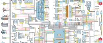
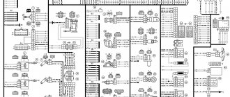
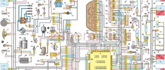
Engine control circuit VAZ-21102, 21103
Engine control circuit for VAZ-21102, VAZ-21103 (controller M1.5.4N, “January-5.1”).
1 - injectors 2 - spark plugs 3 - ignition module 4 - diagnostic block 5 - controller 6 - block connected to the instrument panel wiring harness 7 - main relay 8 - fuse connected to the main relay 9 - electric fan relay 10 - fuse connected to electric fan relay 11 – electric fuel pump relay 12 – fuse connected to the electric fuel pump relay 13 – mass air flow sensor 14 – throttle position sensor 15 – coolant temperature sensor 16 – idle speed regulator 17 – VAZ-21102 oxygen sensor 18 – knock sensor 19 – Crankshaft position sensor 20 – canister purge solenoid valve 21 – immobilizer control unit 22 – immobilizer status indicator 23 – vehicle speed sensor 24 – electric fuel pump with fuel level sensor 25 – oil pressure warning lamp sensor 26 – coolant temperature indicator sensor 27 – level sensor oil 28 - phase sensor (installed on a car with a 16-valve engine) A - block connected to the wiring harness of the anti-lock brake system (ABS) B - block connected to the air conditioner wiring harness C - block connected to the electric fan wiring harness D - wires , connected to the ignition switch (backlight lamp) E - block connected to the blue-white wires disconnected from the ignition switch (when installing the immobilizer) F - to the “+” terminal of the battery G1, G2 - grounding points The diagram uses the designation of the element number circuit to which this wire is connected, for example “-4-”. In some cases, in addition to the designation of the element number, it is given through an oblique fraction and the contact number, for example “-5/15-”. The diagram does not show the connection points of the pink-black, red and green with a red stripe wires.
Pinout of 8-pin connector
- power supply
- speed sensor (electric speedometer)
- fuel consumption (for BC)
- coolant sensor
- emergency oil pressure
- check lamp
- oil level sensor
- tachometer signal
Starter fuse (relay) VAZ 2110
Very often I get a question via email! Which fuse is responsible for the start function on a VAZ 2110 car and where is it located.
I would like to answer it right away - the fuse responsible for the starter on the VAZ dozen does not exist. But there is a starter relay and it is this that very often burns out and fails
How can I close the starter directly?
You can close the starter directly by connecting to the battery or through contacts. Both options work if the device’s anchor is not damaged.
Closing the terminals with a screwdriver, pry bar or wrench
If the traction relay is faulty, the direct closure method is used with any metal rod of the required length. This could be a screwdriver, wrench or pry bar. Problems with the retractor are indicated by a characteristic clicking sound when turning the key in the ignition switch. The starter at this moment is unable to crank the crankshaft, since the Bendix teeth do not cling to the flywheel crown. By closing the starter's power terminals, it will be possible to send current directly to the electrical windings. A wrench or screwdriver will take over the functions of the traction relay.
Before doing this, be sure to put the car on the handbrake and in neutral to avoid accidents. The tool itself should have an insulated handle and a fairly thick shaft. Therefore, it is recommended to use one of the items described above. The pry bar or key can be wrapped with electrical tape at the gripping point.
Closing contacts B and S, M and B is strictly prohibited! Explanation: B – Bold or thick wire – constant voltage contact. On many starters it is closed with a protective rubber cap and marked “+12”. M – Motor or electric motor. S – Start, the contact is made in the form of a threaded outlet, petal or plug, often closed with a plastic tip, so it must be removed before forced closure. 8 – negative contact, connected to the body.
On some car models (VAZ 2109, 2110, 2114), in order to bridge the starter with a screwdriver, you need to dismantle the air filter and disconnect the chip placed on the contact group. After starting the engine, everything comes back together.
You can install the starter relay on the VAZ 2110 yourself
Those people who have a VAZ 2110 have certainly encountered a situation where the starter did not turn after the key was turned, and some clicks are heard, which indicate that the retractor relay is working. In such a situation, the question immediately arises: where is the VAZ 2110 starter relay located and how to find it faster. This question is also relevant when tuning a VAZ 2111.
But we have interesting news for you: the VAZ 2110 simply does not have a starter relay. There is a solenoid relay, to which the positive contact is supplied from the ignition switch. The relay is installed on the starter, its size is 2 times smaller than that of the starter, and it is round in shape.
Next, we will highlight some popular malfunctions that usually arise in the VAZ 2110, related to the VAZ 2110 starter relay and the starter; by the way, a lot of things are used in the VAZ 2115, so by tuning this car, many problems can be avoided.
Connection diagram of the ignition switch to the electrical wiring of a VAZ-2114 car
In the technical documentation for the VAZ-2114 there is a separate section that specifically describes the design of the vehicle’s electrical equipment. So, all the elements are described in full. But, in this particular case, the issue of independently connecting the ignition wires will be considered.
So, let's look at the diagram to see how the contact connections of the ignition switch are connected.
Ignition switch pinout diagram
Regardless of the ignition being turned on, the following devices can operate: high beam, interior and instrument panel lighting, hazard lights, brake light, sound signal, as well as exterior lighting.
A separate item worth highlighting is additional equipment: a car radio (of any format), speakers, additional lighting devices are powered directly into the battery or on-board network, and much more.
Ignition switch device
Next, we will consider the switched circuits of various key positions in the ignition switch:
| Key position | Live contacts | Switched circuits |
| 0 (Disabled) | 30 | _ |
| 1 (Ignition) | 30-15 | Ignition system, generator excitation, headlights, turn signal, control devices, windshield and headlight cleaners and washers, heater fan motor, rear window defroster, cigarette lighter |
| II (Starter) | 30-15 | See Regulation I |
| 30-50 | Starter |
Ignition switch pinout
Product selection
There are several options for the ignition switch on the VAZ-2114. Let's look at each one separately:
- 2110-3704005 or KZ-881 – original catalog numbers of the ignition switch manufactured by AvtoVAZ. The wiring diagram is standard, that is, factory. Installation is quite easy. The average cost is 1000 rubles .
Basic starter malfunctions
The traction relay does not operate after the ignition key has been turned, and the armature does not rotate.
In this situation, it may be due to the following possible problems:
- the battery is broken or discharged, the solution to this problem is to buy a new battery or charge it;
- the positive contacts have oxidized - you just need to clean them;
- it happens that an interturn short circuit occurs on the winding of the traction relay - to correct this situation, you need to install a new relay;
- the circuit that powers the traction relay has broken - you need to check the wires for integrity, and whether they have become disconnected from the circuit?
- contacts “30” and “50” do not close - you just need to change the contact part of the ignition switch;
- The traction relay armature does not work well - you need to remove it and disassemble it, there may be a lubrication problem.
After turning the key, the starter does not start, the armature rotates slowly, and a click is heard in the traction relay.
This situation may arise due to previously similar situations:
- the battery is discharged or disconnected - you need to check and correct the situation;
- the winding of the traction relay is shorted or broken - you also just need to change the relay;
- the ends of the wires have seriously succumbed to oxidation - they need to be checked and cleaned, starting with the battery.
After turning the key, the starter armature spins, but the flywheel does not spin..
This situation arose due to the fact that:
- the freewheel is slipping - you need to diagnose the starter at the stand and replace the clutch if it is faulty;
- The gears on the gearbox are worn out - you just need to replace them.
The starter makes a lot of noise when the armature is spinning.
This problem arose because:
- The liners on the armature or drive shaft bearings have served their service life - you just need to replace the parts that have failed;
- the starter is not secured properly, and the cover could have broken - you just need to secure it or change it;
- the gears on the gearbox, flywheel crown or drive have failed - you just need to change them, or immediately replace the non-functioning parts entirely.
- the gear is constantly engaged with the flywheel; if the clutch on the shaft splines is stuck, it is possible that the armature of the traction relay is stuck - to solve this problem, you need to lubricate the splines with oil. And if the traction relay is stuck, then you need to either change it or use certain methods to get rid of the jam.
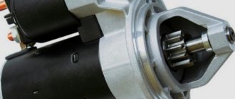
Design and operating principle
The starter is an electrical device that serves to spin the engine crankshaft and thereby initiate the start of the engine itself.
Structurally, it is an electric motor, which includes such elements as:
- frame;
- stator (fixed winding);
- a rotor rotating on three bushings - intermediate and front, which are located in the starter housing, and rear, located inside the transmission housing;
- Bendix, which is a gear mounted on the rear of the rotor shaft. It serves to engage with the flywheel of the motor and transmit rotational motion to it;
- brush assembly, which includes 4 graphite brushes that create a magnetic field that causes the starter rotor to rotate;
- solenoid relay. In addition to the typical relay function of closing/opening an electrical circuit, it performs one more function - it moves the Bendix gear forward and engages it with the flywheel.
When the ignition is turned on, electric current flows through the lock to the relay windings, as a result of which it is activated and, moving the bendix forward, initiates the transfer of rotation from it to the crankshaft flywheel, which, when unwinding, causes the engine to start. After the relay contacts are closed, its supply windings will be de-energized and the bendix will return to its original position under the action of the return spring.
A detailed diagram of the VAZ 2114 starter, clearly telling about its connection to the on-board network and the principle of operation, is presented below.
Replacing the VAZ 2110 starter relay on your own
All drivers know that without a starter, the car not only won’t move, it won’t even start. It drives the crankshaft. In this case, the shaft is accelerated to a certain frequency. As soon as the desired frequency is reached, the engine will start. One of the starter components is a two-winding traction relay. Replacing the VAZ 2110 starter relay is a mandatory procedure, because without the correct operation of this mechanism, the vehicle will not move. On a VAZ 2110, replacing the starter relay can be done on your own.
Removing and replacing the starter tens
Such a repair operation associated with replacing the VAZ 2110 starter, the price of which is quite high, is carried out in the following order:
- The negative contact from the battery (the so-called “ground”) is removed.
- De-energize the wiring of the traction type relay.
- Using a wrench set to “13”, release the positive contact of the starter.
- Unscrew the starter fasteners to the motor clutch housing.
- We dismantle the starter.
- Using a “10” socket, it is necessary to remove the fasteners of the output section of the traction type relay.
- Release the tip of the electrical wire.
- Using a socket head at “8”, remove the relay fasteners.
- Remove the sealing gasket between the relay and the front cover of the electric machine.
- We remove the spring and relay armature from the front cover.
- Assembly is carried out in reverse order.
After disassembling the starter, we begin to inspect it. On the Internet you can watch a video on replacing a VAZ 2110 starter, where all operations are shown in practice. This process starts with the anchor. If the collector becomes dirty or traces of burning are detected, it must be sanded with fine (“velvet”) sandpaper. If there is increased roughness or mica traces between the lamellas, it is necessary to “groove” the collector and carry out the same grinding course.
The anchor is replaced in the following cases:
- if the core beat exceeds 0.08 mm;
- if there is a yellow coating on the anchor shaft from bearing wear, it should be removed with a rag;
- in the presence of burrs and other irregularities;
- inspect the winding at the ends of the armature, the diameter of which should be less than the armature iron package;
- when testing the “control” of the armature winding. The contacts must be connected to the collector plate and the armature core, and no voltage should be supplied. Otherwise, when the lamp lights up, the winding or collector plate may short-circuit to ground.
The starter drive is replaced in the following cases:
- when the clutch is held, the gear receives free circular movement along the clock, and should not move against the clock;
- free movement of the drive along the splined grooves of the shaft;
- with significant wear of drive elements.
Timely replacement of the VAZ 2110 starter bushing will extend the time of effective operation of this electric unit. When inspecting the stator and detecting traces of the passage of the anchor element, it is necessary to change the feed cover and the intermediate type support.