VAZ starter connection diagram
VAZ cars use starters, which are a DC electric motor with an electromagnetic two-winding traction relay and a roller freewheel clutch (overrunning clutch). Starters are used to provide the minimum crankshaft speed required to start the engine. The starter is powered in starting mode from the battery.
The starter relay is connected to the power circuit, thereby closing and opening the circuit, depending on how fast the crankshaft rotates. The starter design on all cars is the same, with only minor design differences. If you understand how the starter works in one car, you can easily figure it out in another.
To prevent a starter failure from taking you by surprise, let’s look at how to replace it yourself. But first, read the theory and study all the options for starter connection diagrams for different models of VAZ cars, collected by the editors of 2 Schemes.ru from familiar auto electricians.
How to install an additional starter relay on a VAZ 2110 Assembly diagram
Until the year 2003, the ignition system of VAZ cars was one of the weakest points in the on-board electrical network. This is due to the generation of high voltage and the inability to unload the starter unit. To solve the problem of a weak starter, vehicle designers and developers adopted the VAZ 2110 auxiliary starter relay.
What exactly does installing an additional relay do?
- Relieves the contact group in the ignition switch
- Prevents sintering of starter contacts due to prolonged ignition
- Opens the electrical circuit when the engine has already started and the ignition key is in the “starter” position
Of course, the additional starter relay for the VAZ 2110 (diagram in the photo) is not a panacea for all the ills of on-board electronics. Experienced experts recommend modernizing the electrical network comprehensively. The list of work may include installation of capacitors, installation of an auxiliary battery, replacement of mass, and other, other work.
To this we can add that not even all the latest modifications of this car have a wiring diagram for the VAZ 2110 starter. If the on-board electrical circuit is well balanced and designed, then an additional relay is not needed at all.
How to check for the presence of an additional relay in the starter?
If you depress the gas pedal and turn the key to the “starter” position, after 12 seconds the starter will automatically turn off. This activates the cylinder purging mode. That is, fuel is not supplied to the working chamber.
If the starter does not turn off, then the relay is missing. In this case, it is advisable to install an additional VAZ 2110 starter relay (the connection diagram is noted in the instructions for this review).
What is needed to install an additional relay?
- Relay with 4 contacts with current strength from 30 to 40 (A). The most commonly used is the 30 amp relay.
- Reinforcement with a cross-section around 1.5 (mm2)
- Flat female connectors (5 pcs)
- Flat male connector (1 pc)
- Ring connectors for 6 and 8 (mm)
When the materials are prepared, let's look at how to connect the starter relay. By the way, there is an intelligible video on this topic:
Please note that car dealerships sell ready-to-install additional relay kits. This set contains both good wire and high-quality ring connectors
All elements are marked and made in the same style. It is easy and pleasant to work with such materials yourself.
VAZ 2101 starter connection diagram
- starter;
- holding winding of traction relay;
- ignition switch;
- generator VAZ 2101;
- fuse box;
- pull-in winding of the traction relay;
- accumulator battery.
Under normal loads, the current generated by the starter is 150 A. When heavy loads occur, for example in winter, the resulting current can reach 500 A. This is a serious test for this electrical unit, so it is not recommended to keep the key on the start for more than 10 seconds, and repeated starting attempts must be made with a break of at least a minute.
VAZ 2106 starter connection diagram
- starter;
- generator;
- accumulator battery;
- pull-in winding of the traction relay;
- ignition switch;
- traction relay holding coil
| 1 – drive side cover; | 14 – relay cover; |
| 2 – retaining ring; | 15 – contact bolts; |
| 3 – restrictive ring; | 16 – collector; |
| 4 – drive gear; | 17 – brush; |
| 5 – overrunning clutch; | 18 – armature shaft bushing; |
| 6 – drive ring; | 19 – cover from the collector side; |
| 7 – rubber plug; | 20 – casing; |
| 8 – drive lever; | 21 – shunt coil of the stator winding; |
| 9 – relay anchor 2106; | 22 – body; |
| 10 – holding winding of the traction relay; | 23 – stator pole fastening screw; |
| 11 – pull-in winding of the traction relay; | 24 – anchor; |
| 12 – relay coupling bolt; | 25 – armature winding; |
| 13 – contact plate; | 26 – intermediate ring. |
DIY starter repair
Maintenance or repair of the starter must be carried out in accordance with certain algorithms, compliance with which requires certain experience and knowledge, as well as the use of the necessary tools. Troubleshooting always begins with disassembling the starter, after which diagnostics are carried out, and if problems are detected, repairs are carried out.
Tools and Supplies
To troubleshoot, you need to prepare the following tools:
- Socket heads for 13 and 15.
- Extension.
- Handle equipped with a ratchet.
- Ohmmeter.
- A special analyzer equipped with a light bulb.
- Phillips and flathead screwdrivers.
Spare parts will be used as consumables to replace failed components. You can determine which parts require replacement at the diagnostic stage described above. To repair the starter, it is recommended to use only high-quality parts.
How to remove and disassemble
To prepare for repairs, it is necessary to completely disassemble the starter. This procedure should be carried out in the following sequence:
- Remove the negative battery terminal.
- Remove the air filter housing to ensure convenience for further operations.
- Disconnect the wire leading to the traction relay.
- Place the disconnected wiring to the side so that it does not interfere with further repairs.
- Unscrew the nuts that secure the starter to the gearbox.
- Remove the unit and carry out further repairs in more convenient conditions.
- Disconnect the wire that is in contact with the mounting bolt.
- Remove the traction relay. To do this, you need to unscrew the two bolts that secure it.
- Remove the relay armature. To do this, you need to lift it up a little, and then remove the loop from the lever.
- Unscrew the nuts securing the tie rods.
- Remove the cover with the drive, as well as the gearbox assembly.
- Completely “remove” the tie rods. This will make it easier to further remove the drive and gearbox.
- Remove the planetary gears. They need to be replaced if there is damage to the teeth or the integrity of the needle bearings is compromised.
- Replace the brush holder assembly (if necessary).
- Remove the cover from the manifold side.
- Unscrew the two screws and then remove the brush holder from the cover.
- Bend the clips and remove the spring.
- Check the anchor for defects. To do this, you need to remove it from the case.
- Remove the gear from the anchor shaft.
- Remove the armature from the stator mechanism.
- Remove the sealing support from the lever.
- Knock the stopper off the retaining ring using a special mandrel.
- Dismantle the restrictor and retaining rings.
- Remove the drive assembly.
General view of a completely disassembled starter
Assembly must be done in reverse order.
Troubleshooting
When conducting a full check of the functionality of the VAZ 2110 starter, you must act in accordance with the following algorithm:
- Check how well the unit rotates. If the crankshaft moves poorly, you should pay attention to the presence of lubricant and, if necessary, lubricate the mechanisms. There are situations when the oil does not correspond to the current season. Replacing it with a more suitable one will solve the problem.
- Check the battery for charge and oxidation of tips and inputs. If necessary, it is necessary to charge and replace failed elements. In such a situation, it is necessary to carry out maintenance of the contact group and the battery itself, after which the functioning of the starter will be restored.
- Inspect the brushes and check the tightness of the wire ends. To do all the necessary actions, you will need to dismantle and disassemble the device, clean the commutator, replace the brushes and adjust the degree of spring tension.
- Determine the presence or absence of clutch slipping. If necessary, it is necessary to completely replace the starter drive. Another way to solve the problem is to wash the threaded shaft and then lubricate it.
- Inspect the flywheel ring teeth for nicks. Their presence may be indicated by a characteristic grinding sound. To eliminate it, you will need to eliminate the nicks or install a new buffer spring if the old one is noticeably weakened.
- Carry out diagnostics of the starter pole fastening. Its weakening may be indicated by the characteristic noise present during operation of the mechanism. The problem can be solved by securely fastening the starter or reinforcing the said fastening.
To ensure that the bolt is in contact with the plate, it is necessary to measure the resistance on the contact bolts
If you check using the described algorithm, you will be able to accurately determine the “source” of the malfunction and effectively eliminate it. However, there are breakdowns that cannot be eliminated during an inspection.
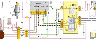
Starter diagram VAZ 2108, 2109, 21099
Electric current enters the starter circuit from terminal “30” of the generator. Next, through block Ш8 (Х8) of the mounting block (pins 5,6), block Ш1 (Х1) - pink wire, to the ignition switch. The driver turns the key in the ignition to turn on the starter (position 2) and closes the contacts (50, 30). After which the ignition switch, through the red wire, current flows to block Ш1 (X1) of the mounting block (pin 8), then block Ш5 (Х5) (pin 4), starter switch relay (pin 85). The relay is activated. From terminal “30” of the start relay, current flows to terminal “50” of the starter traction relay, energizing its winding. The traction relay is activated, activating the starter.
The starter electrical circuit uses a switching relay 111.3747-10.
- Screw securing the protective cap.
- Protective cap.
- Retaining half ring.
- Rear cover fastening nut.
- Back cover.
- Brush springs.
- Brush guides (outer part).
- Brushes.
- Stator.
- Anchor.
- Drive lever.
- Drive unit.
- Restriction ring.
- Retaining ring.
- Drive lever axis.
- Screws for securing the traction relay.
- Front cover.
- Plastic sealing ring for the lid.
- Tie rods.
- Rubber plug.
- Traction relay core.
- Return spring.
- O-ring for traction relay.
- Traction relay.
- Sealing washer.
- Adjusting washers.
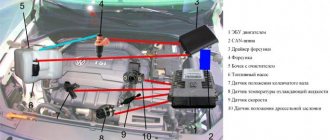
Where is the starter on a VAZ 2112 16 valves?
Dear visitors of the site “All about cars”! We will be very grateful to you for your comments on the video clip “Where is the starter on the VAZ 2112 16 valves”, registration is not required for this. We also ask you to let us know if you have any problems playing the video.
Well, what was the reason? Contact group or relay
What couldn’t be checked with a screwdriver? without removing the starter
the anchor burned out there after all, I still initially sinned on the solenoid relay
It would be useless, because I wouldn’t shoot another video because of this. It burned out completely.
The other day the starter also stopped working. VAZ 2114 was standard Belarusian. Didn't even bother with the repairs. I bought a new KOTEK for 3t. R. It starts with a click and buzzes like a bee. I advise everyone
I’m a teapot, where else can I put the air down if there’s no snowdrift nearby?
4. 28 than the reason
The battery must be disconnected before removing the air flow sensor chip, and not after. So you can burn it.
But I still didn’t take any risks and postponed the repairs until the winter, which I advise you to do as well.
The video needs to be renamed. The title does not match the content. How did you remove the bottom mount? The name of the video is repairing the starter or the reasons for the starter dying.
Before removing the MAF chip, you need to remove the terminal from the battery, otherwise you can then buy a new one.
Change the ignition switch, same thing happened.
Why show the left details, something like an air blower, it’s already clear to everyone what it looks like and how to shoot it….
What was the problem?
And I add. I plugged in the relay and everything worked for me. I connected the lamp to the red wire before - the current was flowing... But the current was weak. I still haven't found the ignition relay. Therefore, the most likely cause is the ignition switch. But this is a disease, as I understand it, in the tags. So it's better to add extra. relay. The current on the wires drops less and the chisel starts up faster now: There is really a possibility that the connector is simply stuck on the retractor. Emery solves this problem.
So what was the reason? What's next? -Egnition lock? -Wiring?
write why do you need to remove the hood lock wire? and how to unscrew the starter bolt from below if there is no pit, lift, or garage.
the importance is in the little things, but they are not there, what and how to unscrew is not said or shown, there is no point in the video, I filmed it for one, don’t make it accessible to everyone, there is so much garbage on the Internet
Starter circuit for VAZ 2110, 2111, 2112
Starters of type 57.3708 were installed on VAZ-2110 cars and had the following technical characteristics:
- Rated power 1.55 kW
- Current consumption at maximum power no more than 375 Amperes
- Current consumption in the inhibited state is no more than 700 Amperes
- Current consumption in idle mode no more than 80 Amperes
The connection diagram for the starter for the ten is shown above, here is its explanation:
- battery
- generator
- the starter itself
- egnition lock
| 1 – drive shaft; | 20 – contact bolts; |
| 2 – front cover bushing; | 21 – output of “positive” brushes; |
| 3 – restrictive ring; | 22 – bracket; |
| 4 – gear with the inner ring of the overrunning clutch; | 23 – brush holder; |
| 5 – overrunning clutch roller; | 24 – “positive” brush; |
| 6 – drive shaft support with liner; | 25 – armature shaft; |
| 7 – planetary gear axis; | 26 – tie rod; |
| 8 – gasket; | 27 – back cover with bushing; |
| 9 – lever bracket; | 28 – collector; |
| 10 – drive lever; | 29 – body; |
| 11 – front cover; | 30 – permanent magnet; |
| 12 – relay anchor; | 31 – armature core; |
| 13 – holding winding; | 32 – armature shaft support with liner; |
| 14 – retractor winding; | 33 – planetary gear; |
| 15 – traction relay; | 34 – central (drive) gear; |
| 16 – traction relay rod; | 35 – carrier; |
| 17 – traction relay core; | 36 – gear with internal teeth; |
| 18 – contact plate; | 37 – layering ring; |
| 19 – traction relay cover; | 38 – hub with the outer ring of the overrunning clutch. |
Some design features
The part in question consists of the following elements:
- Steel electric motor. Its purpose is to remove heat. In addition, it is characterized by water-repellent characteristics. This circumstance ensures that there is a situation in which you can wash the engine without any fear. Water will not be able to penetrate current-carrying parts, and therefore will not cause harm.
- The housing is the location of the solenoid relay. The flywheel and gear are fixed using its lever. This ensures that torque is transmitted. Copper contacts are connected to the core. They transmit voltage from the battery.
- The anchor is the attachment point for the commutator elements, windings, and gears.
- When the car is started, the flywheel is connected to the starter via a bendix. As soon as the car starts, all elements return to their original position.
- The brushes are fixed with holders and allow them to be quickly replaced if necessary.
The starter is fully functional thanks to the presence of two relays. They should be clearly distinguished from each other. The first element is used to turn on the starter. The second device is a pull-in relay. It is located directly on the starter. For VAZ 2110, the starter relay is of great importance for the operation of the tens.
This device is intended for the following purposes:
- Thanks to it, after starting the engine, the gear returns to its original position.
- The energy required by the starter motor and the electromagnetic relay is redistributed.
- The bendix gear is fed.
- Thanks to the device, all parts work synchronously when the engine starts.
It should be said that this part fails quite often, so the VAZ 2110 starter relay needs to be replaced. But getting to it is not so easy. In this case, you will need to disassemble the starter itself.
Starter solenoid relay
The starter relay is called a pull-in relay. This is due to the principle of its operation - it performs the function of connecting the starting device to the electrical circuit and connecting its armature to the crankshaft. It happens like this: when no current is supplied to the windings of the device, its armature, under the action of the return spring, remains in the forward position. The same spring, through a special fork, holds the Bendix gear, preventing it from engaging with the crankshaft flywheel ring.
By turning the key in the ignition, we supply current to the winding of the device. Under the influence of an electromagnetic field, the armature is fed back (pulled into the housing), closing the starter power contacts. The Bendix gear also moves, engaging with the flywheel. At the same moment, the retracting winding is turned off, and the holding winding comes into play. The force from the starter shaft is transmitted through the gear to the flywheel, causing the crankshaft to rotate until we no longer hold the ignition key in the start position.
What functions does the solenoid relay perform:
- Protects the starter from shorting contacts in the ignition.
- In order to turn off the power to the starter in a situation where the engine is running and the key shows the “starter” mode.
- Provides relief of contacts in the ignition switch.
When the engine starts, voltage from the generator goes to the relay coil. Then the gears of the drive system begin to work, due to which a magnetic field is created. The flywheel of the propulsion system is working. The gear begins its work thanks to the holding winding, while the bolts are closed. When the key is returned to the ignition switch, the winding is de-energized, thus disconnecting the gear and flywheel. This scheme applies to modern cars, including VAZ models.
If the starter makes a loud noise, the pole or starter could be loose. In the first situation, strengthen the fastening by tightening the screw, and in the second, secure the starter. If you disassemble the starter and see that the clutch is starting to slip, then the only thing you need to do is replace the starter drive.
The principle of operation of the starter and its main elements
With the help of the starter, the primary rotation of the engine crankshaft begins until the power unit starts up due to the ignition of the oxygen-gasoline mixture. This electric machine is a constant current EDC with 4 brushes of a four-pole type, which initiates the excitation moment using permanently installed magnetic elements, so replacing the VAZ 2110 starter is necessary in case of its failure.
It includes a freely rotating roller-type clutch, a traction relay with 2 windings, and a planetary gearbox. The traction relay with 2 windings is the most significant element of the starter. With its help, the drive gear is brought into engagement with the rim of the motor flywheel. In addition, it determines how the starter motor receives power.
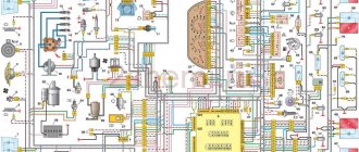
VAZ 2110 diagram
Colored wiring diagrams for the VAZ 2110 (injector and carburetor engine) are provided with a description of all elements for various modifications. The information is intended for self-repair of the car. Electrical circuits are divided into several blocks for ease of viewing via a computer or smartphone; there are also circuits in the form of a single picture with a description of the elements - for printing on a printer in one sheet.
There are two types of electrical wiring for the VAZ-2110: carburetor and injector. There are slight differences, but the basic principles of operation and wiring are the same. Depending on the location, the wiring differs into: under the hood and in the cabin. All electrical equipment of the car is connected using wires of a certain color. Each element has its own wiring harness through the blocks and fuses.
Starter replacement
You can remove the starter yourself, as the procedure is quite simple. You need to start by preparing the tools for work.
Required tools:
- Extension.
- Handle with ratchet.
- Socket head for 15 and 13 mm.
Attention! Removal can begin after disconnecting the negative terminal from the battery. This applies not only to dismantling the starter, but also to any other work related to electricity.
To make the process easier, you need to remove the air filter housing.
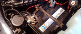
- The next step is to disconnect the wiring from the solenoid relay. It is important to ensure that the positive wire is also unscrewed from the terminal. The photo shows the elements that we need to dismantle.
If it is no longer possible to repair the VAZ 2110 starter yourself, then replace it with a new unit yourself in the reverse order.
VAZ 2110 - modifications
VAZ-21100 . The base model which was produced from 1996 to 2000. The car was equipped with an 8-valve carburetor VAZ-21083 engine with a displacement of 1.5 liters and a power of 69 horsepower.
VAZ-21101 . This modification has been produced since 2004, equipped with an 8-valve gasoline injection engine with a displacement of 1.6 liters.
VAZ-21102. Like the previous modification with an 8-valve injection engine, but with a volume of 1.5 liters.
VAZ-21103 . Modification of the “tens” with a 16-valve injection engine with a working volume of 1.5 liters.
VAZ-21103M . A restyled modification of the VAZ-21103, equipped with a 16-valve petrol injection engine with a displacement of 1.5 liters and a power of 92 horsepower. Produced since 2002.
VAZ-21104 . The modification is equipped with a 16-valve petrol injection engine with a working volume of 1.6 liters.
VAZ-21104M . A restyled modification of the VAZ-21104, equipped with a 16-valve petrol injection engine with a displacement of 1.6 liters. Produced since 2004.
VAZ-21106 GTI . The engine of the VAZ-21106 GTI is the most powerful and expensive modification that has been produced since 2000. The car was equipped with a 2-liter 16-valve Opel C20XE gasoline engine with a capacity of 150 horsepower. The car was fitted with a body kit with swollen arches, and the track was widened by 76 millimeters. It was equipped with R15 wheels with low-profile tires.
VAZ-21106 Coupe . Coupe VAZ-21106 in a coupe body. A distinctive feature of the car was the presence of only two doors, which were lengthened by 250 millimeters, while the body was shortened by 170 millimeters. The engine was installed the same as in the previous VAZ-21106 GTI model.
VAZ 21106 WTCC . A sports modification of the 106 model, it participated in the 2008 FIA WTCC international championship.
VAZ 21107 . Modification of a car for rally competitions. It was equipped with a welded safety cage and a different suspension design.
VAZ 21108 "Premier" . A modification with a body lengthened by 170 millimeters in the rear door area, which provided more convenient entry and exit of passengers. It was equipped with a 1.5-liter injection 16-valve engine.
VAZ 21109 “Consul” . 4-seater luxury limousine based on the VAZ-2110 car. In addition to the length of the body, the dimensions of the rear door were also increased, for more convenient entry and exit of passengers. Equipped with a 1.5 liter engine and R14 or R15 wheels. Overall dimensions: length - 4950 mm, width - 1700 mm, height - 1440 mm. Fuel consumption in the urban cycle is 9.5 liters per 100 kilometers.
VAZ 2110-91 . Modification of the VAZ-2110 with a 1308 cm3 rotary piston engine. The car could reach speeds of up to 240 km/h, and acceleration from 0 to 100 km/h took 6 seconds.
A car with a 16-valve injection engine in the Gran Lux configuration includes:
- Electric windows;
- Door locking;
- Trunk lock lock;
- Velvet seat upholstery;
- Immobilizer;
- Heated front seats;
- Ventilated 14-inch brake discs;
- Rear spoiler with additional brake light;
- Fog lights.
Wiring diagram for VAZ 2110 carburetor
In the instrument panel wiring harness, the second ends of the wires of white, black, orange, white with a red stripe and yellow with a blue stripe are connected to each other at the same points. The bends of the wires at the points of entry into the harness indicate the direction of their laying in the bundle.
See the complete diagram in one file below (click to enlarge):
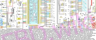
1 – headlight 37 – instrument cluster 2 – front brake pad wear sensor 38 – rear fog light switch 3 – fan motor switch 39 – fog light indicator lamp 4 – engine cooling system fan electric motor 40 – rear window heating indicator lamp 5 – sound signal 41 – clock 6 – generator 42 – rear window heating switch 7 – oil level sensor 43 – steering column switch 8 – carburetor solenoid valve control unit 44 – block for switching wires when installing headlights of another type 9 – heater controller 45 – switch instrument lighting 10 – recirculation valve switch 46 – ignition switch 11 – illumination lamp for heater control levers 47 – connectors for connecting the headlight cleaner wiring harness 12 – switch 48 – socket for a portable lamp 13 – carburetor limit switch 49 – directional light 14 – control sensor oil pressure lamps 50 – brake light switch 15 – spark plugs 51 – interior lamp 16 – carburetor solenoid valve 52 – on-board control system unit 17 – coolant temperature indicator sensor 53 – fuel level indicator sensor 18 – ignition distributor 54 – hazard warning switch 19 – ignition coil 55 – driver’s seat belt sensor 20 – starter 56 – cigarette lighter 21 – heater fan motor 57 – ashtray backlight lamp 22 – additional resistor for heater motor 58 – glove compartment light switch 23 – speed sensor 59 – connector for on-board computer 24 – reverse light switch 60 – glove box lighting lamp 25 – micromotor gearbox for heater flap drive 61 – side turn signal 26 – recirculation valve 62 – switch in the front door pillar 27 – brake fluid level sensor 63 – switch in the rear door pillar 28 – pads for connecting the rear window washer motor 64 – parking brake warning lamp switch 29 – battery 65 – trunk light 30 – windshield washer motor 66 – interior air temperature sensor 31 – washer fluid level sensor 67 – external rear light 32 – level sensor coolant 68 – internal rear light 33 – windshield wiper motor 69 – license plate light 34 – mounting block 70 – block for connecting the rear window heating element 35 – blocks for connecting the warning light harness 71 – block for connecting an additional brake signal 36 – outdoor light switch
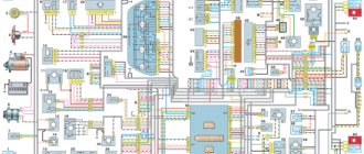
Diagram of VAZ 2110 injector 8 valves
1 – headlight 2 – front brake pad wear sensors 3 – horn 4 – cooling system fan 5 – reverse light switch 6 – battery 7 – generator 8 – oil pressure warning lamp sensor 9 – oil level sensor 10 – spark plugs 11 – injectors 12 – idle speed control 13 – electronic control unit blocks 14 – throttle position sensor 15 – crankshaft position sensor 16 – ignition module 17 – coolant temperature indicator sensor (for instrument cluster) 18 – starter 19 – diagnostic block 20 – coolant temperature sensor (for the engine management system) 21 – speed sensor 22 – fuel pump switch relay 23, 35, 39 – fuses 24 – electric fuel pump 25 – micromotor gearbox for heater damper drive 26 – recirculation valve 27 – heater fan 28 – windshield washer pump windows 29 – washer fluid level sensor 30 – brake fluid level sensor 31 – coolant level sensor 32 – windshield wiper gear motor
33 – additional heater fan resistor 34 – injection system power supply relay 36 – canister purge valve 37 – mass air flow sensor 38 – cooling system fan activation relay 40 – external lighting switch 41 – knock sensor VAZ-2110 injector 42 – oxygen concentration sensor ( heated lambda probe) 42* – CO potentiometer (installed on cars running on leaded gasoline; in this case, an oxygen concentration sensor is not installed) 43 – fog light indicator lamp 44 – rear window heating indicator lamp 45 – fog light switch 46 – rear window heating switch 47 – instrument cluster 48 – mounting block 49 – fuel level sensor 50 – ignition switch 51 – instrument backlight brightness control 52 – steering column switch 53 – heater control lever illumination lamp 54 – hazard warning switch 55 – electronic heater control unit; 56 – recirculation valve switch 57 – on-board control system display unit 58 – side direction indicators 59 – temperature sensor for the heating system 60 – interior lamp 61 – front interior lamp 62 – socket for a portable lamp 63 – electronic clock 64 – switches in the racks front doors 65 – switches in the rear door pillars 66 – glove compartment lighting lamp 67 – glove compartment lighting switch 68 – cigarette lighter 69 – ashtray lighting lamp 70 – brake light switch 71 – rear window heating element 72 – external rear lights 73 – internal rear lights 74 – license plate lamps 75 – trunk lighting lamp
See the complete diagram in one file below (click to enlarge):
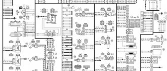
Diagram of VAZ 2110 injector 16 valves
1 - headlight 35 - instrument lighting switch 2 - front brake pad wear sensors 36 - ignition switch 3 - reverse light switch 37 - mounting block 4 - engine cooling fan electric motor 38 - recirculation valve switch 5 - sound signal 39 - controller heater 6 - right front door locking motor 40 - hazard warning switch 7 - power window relay 41 - heater control lever illumination lamp 8 - 8 A fuse 42 - glove compartment lighting lamp 9 - starter 43 - glove compartment lighting lamp switch 10 - battery 44 - cigarette lighter 11 - generator 45 - on-board control system display unit 12 - windshield washer motor 46 - ashtray lighting lamp 13 - washer fluid level sensor 47 - brake signal switch 14 - left front door locking motor 48 - locking motor left rear door 15 — power window switch of the left front door 49 — power window switch of the left rear door 16 — coolant level sensor 50 — power window motor of the left rear door 17 — windshield wiper motor 51 — socket for a portable lamp 18 — recirculation valve 52 — clock 19 - micromotor gearbox for heater flap drive 53 - gearmotor for electric window lift on the right rear door 20 - electric motor for heater 54 - power window switch at the right rear door 21 - trunk lock switch 55 - gearmotor for locking the right rear door 22 - power window switch at the right front door 56 - side turn signal 23 - electric window motor of the right front door 57 - parking brake warning lamp switch 24 - door lock system control unit 58 - driver's seat belt sensor 25 - additional heater motor resistor 59 - directional light bulb 26 - brake fluid level sensor 60 - interior light bulb 27 - electric window motor of the left front door 61 — interior air temperature sensor 28 — exterior lighting switch 62 — switch in the front door pillar 29 — instrument cluster 63 — switch in the rear door pillar 30 — rear fog light switch 64 — external rear light 31 — warning lamp fog light 65 - interior rear light 32 - rear window heating indicator light 66 - license plate lights 33 - rear window heating switch 67 - trunk light 34 - steering column switch A - blocks for connecting the rear window washer motor B - blocks for connecting the harness injection system C - to the warning light harness block D - block for connection to the on-board computer E - to the headlight cleaner harness block F - block for connection to the fuel level sensor in the electric fuel pump module G - to the rear window heating element H - block for connecting an additional signal braking J - to the trunk lock motor
Electrical circuit of ECM VAZ-21101
1 — VAZ-21101 controller; 2 — block of the ignition system harness to the ABS cabin group harness; 3 — diagnostic block; 4 — immobilizer warning sensor; 5 — immobilizer control unit; 6 — ignition coil; 7 — spark plugs; 8 — nozzles; 9 — electric fuel pump; 10 — block of the ignition system harness to the fuel level sensor harness; 11 — block of the fuel level sensor harness to the ignition system harness; 12 — block of the ignition system harness to the injector harness; 13 — injector harness block to the ignition system harness; 14 — speed sensor; 15 — idle speed regulator; 16 — throttle position sensor; 17 — coolant temperature sensor; 18 — mass air flow sensor; 19 — oil pressure warning lamp sensor; 20 - phase sensor; 21 — oxygen sensor; 22 — crankshaft position sensor; 23 — knock sensor; 24 — solenoid valve for purge of the adsorber; 26 — coolant temperature indicator sensor; 27 — block of the ignition system harness to the instrument panel harness; 28 — block of the instrument panel harness to the ignition system harness; 29 — controller power supply fuse; 30 - ignition relay; 31 - ignition relay fuse; 32 — fuse for the electric fuel pump power supply circuit; 33 — electric fuel pump relay; 34 — electric fan relay; 35 — ignition system harness block to the air conditioner connector; 36 — block of the ignition system harness to the side door harness. 37 — electric fan of the cooling system; 38 — diagnostic connector; 39 — ignition switch; 40 — instrument cluster; 41 — on-board control system unit; 42 — starter relay; 43 — contacts of the 8-terminal blocks of the instrument panel harness and the front harness; 44 — contacts of the 21-terminal blocks of the instrument panel harness and the rear harness; 45 - trip computer.
- A - to the “plus” terminal of the battery;
- B1 — grounding point of the fuel level sensor harness;
- B2, B3 — grounding points of the ignition system harness;
- C - to the starter;
- D - to the driver's door interior lamp switch.
Communities VAZ Repair and Modification Blog Installing an additional starter relay
I read on the forums, I’m not the only one with a similar problem, maybe it will help someone else. I suffered for a long time with the problem of starting the car while it was hot. The problem was especially noticeable in the summer. At times the starter simply refused to turn, you turn the key, there’s a click, the instrument panel dims a little and that’s it... the starter is silent. The problem is not constant, this can happen once a week, maybe every other day. You can drive the car all day, turn it off, start it, everything works, and at some inopportune moment it stops responding to the key. You stop at a gas station or at a store and that’s it. You start running with a screwdriver into the hood and closing the contacts on the retractor, and it starts with a screwdriver. If you start it with a screwdriver and then turn it off, you can start it with the key without any problems and again you can drive for an unknown number of days or hours, etc. To. The problem is floating and intermittent. During the search for the cause, I went through the starter, changed the brushes, installed a new retractor (but in vain), cleaned all the contacts, cleaned the contact group of the ignition switch. I did all this in stages because After each action, the problem seems to disappear, but only for a while, you drive for a month and again it’s unexpected. As I found out, the problem arose at the slightest drain of the battery, like turning on a Carlson, when the engine warms up or listening to music with the engine off. After that, there was simply not enough voltage through the ignition switch, somewhere there was apparently a voltage loss from bad contacts, perhaps the contact group needed to be changed and not cleaned (but it’s not a fact that a new one would have lasted a long time). I decided to install a starter relay and at the same time I made additional mass .I bought a 4-pin 30A relay, five female connectors, one male connector and a couple of ring connectors.
I took out the BPVL 4.0 cable from the cradles. I made it in three layers, crimped it and tinned the contacts and covered everything on top with corrugation. I threw the mass onto the generator and onto the starter. I also replaced the original mass of the body, it was too flimsy.
Engine control circuit VAZ-21102, 21103
Engine control circuit for VAZ-21102, VAZ-21103 (controller M1.5.4N, “January-5.1”).
1 - injectors 2 - spark plugs 3 - ignition module 4 - diagnostic block 5 - controller 6 - block connected to the instrument panel wiring harness 7 - main relay 8 - fuse connected to the main relay 9 - electric fan relay 10 - fuse connected to electric fan relay 11 – electric fuel pump relay 12 – fuse connected to the electric fuel pump relay 13 – mass air flow sensor 14 – throttle position sensor 15 – coolant temperature sensor 16 – idle speed regulator 17 – VAZ-21102 oxygen sensor 18 – knock sensor 19 – Crankshaft position sensor 20 – canister purge solenoid valve 21 – immobilizer control unit 22 – immobilizer status indicator 23 – vehicle speed sensor 24 – electric fuel pump with fuel level sensor 25 – oil pressure warning lamp sensor 26 – coolant temperature indicator sensor 27 – level sensor oil 28 - phase sensor (installed on a car with a 16-valve engine) A - block connected to the wiring harness of the anti-lock brake system (ABS) B - block connected to the air conditioner wiring harness C - block connected to the electric fan wiring harness D - wires , connected to the ignition switch (backlight lamp) E - block connected to the blue-white wires disconnected from the ignition switch (when installing the immobilizer) F - to the “+” terminal of the battery G1, G2 - grounding points The diagram uses the designation of the element number circuit to which this wire is connected, for example “-4-”. In some cases, in addition to the designation of the element number, it is given through an oblique fraction and the contact number, for example “-5/15-”. The diagram does not show the connection points of the pink-black, red and green with a red stripe wires.
Pinout of 8-pin connector
- power supply
- speed sensor (electric speedometer)
- fuel consumption (for BC)
- coolant sensor
- emergency oil pressure
- check lamp
- oil level sensor
- tachometer signal
Electrical circuit of ECM VAZ-21104
1 — block of the ignition coil wiring harness to the ignition system harness; 2 — block of the ignition system harness to the ignition coil wiring harness; 3 — ignition coils VAZ-21104; 4 — immobilizer warning sensor; 5 — immobilizer control unit; 6 — spark plugs; 7 — nozzles; 8 — diagnostic block; 9 — block of the ignition system harness to the ABS cabin group harness; 10 - controller; 11 — electric fuel pump; 12 — block of the ignition system harness to the fuel level sensor harness; 13 — block of the fuel level sensor harness to the ignition system harness; 14 — block of the ignition system harness to the injector harness; 15 — injector harness block to the ignition system harness; 16 — block of the ignition system harness to the side door harness; 17 — speed sensor; 18 — idle speed regulator; 19 — throttle position sensor; 20 — coolant temperature sensor; 21 — mass air flow sensor; 22 — oil pressure warning lamp sensor; 23 - phase sensor; 24 — oxygen sensor; 25 — crankshaft position sensor; 26 — knock sensor; 27 — solenoid valve for purge of the adsorber; 28 — oil level sensor; 29 — coolant temperature indicator sensor; 30 — block of the ignition system harness to the instrument panel harness; 31 — block of the instrument panel harness to the ignition system harness; 32 — ignition relay; 33 - ignition relay fuse; 34 — fuse for the electric fuel pump power supply circuit; 35 — electric fuel pump relay; 36 — electric fan relay; 37 — controller power supply fuse; 38 — ignition system harness block to the air conditioner connector; 39 — instrument cluster; 40 — ignition switch; 41 — electric fan of the cooling system; 42 — on-board control system unit; 43 — starter relay; 44 — contacts of the 8-terminal blocks of the instrument panel harness and the front harness; 45 — contacts of the 21-terminal blocks of the instrument panel harness and the rear harness; 46 — trip computer; 47 - diagnostic connector.
- A - to the “plus” terminal of the battery;
- B1 — grounding point of the ignition coil wiring harness;
- B2 — grounding point of the fuel level sensor harness;
- B3, B4 - grounding points of the ignition system harness;
- C - to the starter;
- D - to the driver's door interior lamp switch.
According to the scheme described above, fuel regulation in a car is carried out. Moreover, it depends not only on the load of the valves in the engine, but also on the corresponding position relative to the throttle valve. With the help of a diagram of electrical wiring and valves, it is possible to understand which of the relays or fuses is malfunctioning and replace it in time. In this case, one of the main roles when supplying fuel is played by electrical equipment (controllers) that regulates the operation of the injector.
Source
Where is the Starter Relay for VAZ 2115 Injector?
Starter relay VAZ 2115
The most likely cause of starter failure is electrical damage.
When the engine starts unsuccessfully for the first time, most people look for a problem in the starter, which is not always correct. The operation of the starter directly depends on the relay, contact connections and the availability of the necessary electricity. To check if the electric starter is working, it can be powered directly from the battery by connecting the positive wire from the terminal.
This way, you can start the engine to continue driving with a faulty starter power system. Many people try to find a VAZ 2115 starter relay in a car, where there is a component of the car’s electronic system, but the search does not produce results. This happens for the simple reason of its absence.
Perhaps the VAZ manufacturer is already equipping the new series of cars with a starter relay, but previous versions of these cars were manufactured without it. This is not critical, since the cost is negligible and the benefits are immediately visible; you can install it yourself, without the skills of an electrician.
Why is it necessary to install an additional VAZ 2115 starter relay? An additional relay ensures more stable operation of the starter with additional electrical equipment. Thus, the starter works even with a weakly charged battery, the backlight on and at low temperatures.
VAZ 2115 does not turn the starter, fix the problem
Installing the relay
for
starter
and 2110.
Do not confuse the VAZ 2115 starter relay with the repeater, which is located on the starter and performs the function of pushing and retracting the mechanism for engaging the starter teeth and the flywheel. Thus, a normal car start. Retractor malfunctions are expressed in the following manifestations:
- After the engine has started successfully, you may hear the starter whirring.
- Turn the ignition key with a simple click, the starter does not work
- try to start the engine with the key
Such manifestations are characterized by a violation of the starter and replacement of the relay.
Repair of the retractor starting relay VAZ 2115
First remove the starter by unscrewing the mounting bolts and before disconnecting the battery. Remember. The main thing. ensure the safety of repairs. After successfully removing the electric starter, you need to unscrew the solenoid relay bolts.
In most cases, the relay relay will not fold, but it can still be repaired. To do this, you will need a screwdriver, a soldering iron, a copper winding, a core, which, if you look, may turn out to be intact. In this case, you don't need to change it.
When soldering the wire with a soldering iron, you can move on to expanding the coil body. By separating the coil, you can determine its damage and replace the necessary elements.
Read the same, other reviews
- Replacing a VAZ 2114 cluster starter