Here the diagram of VAZ of various models is presented and described. Detailed descriptions of all electrical devices of these circuits are provided. A definition of what a VAZ scheme is is derived. The symbols for the diagrams of all brands of VAZ cars have been deciphered. Electrical diagrams of the most important units of VAZ cars are laid out and painted separately.
The VAZ scheme consists of two halves. In its center is the fuse and relay mounting block. Wires from all electrical devices converge to the mounting block. Through it you can check all electrical circuits of all devices in the car. To quickly find the circuits connecting individual electrical devices of a VAZ car, their diagrams are presented in separate subsections
The VAZ diagram is a plan of the electrical circuits of these car brands, connecting all electrical devices into one whole. All electrical circuits in the VAZ circuit converge in the mounting fuse block. In it they are connected to blade fuses that protect them from short circuits. In turn, the fuse box receives power from the battery and an electric generator.
VAZ circuit diagrams of all passenger car models are designed and installed according to the one-wire rule. The negative conductor is the car body. Almost all wires laid on the car body serve as positive conductors.
List of VAZ schemes:
- 1 — Electrical diagram of VAZ 2114 injector 8 valves
- 2 — Scheme VAZ 2110, 2111, 2112
- 3 — Electrical diagram of the fuse box VAZ 2110, 2111, 2112
- 4 — Electrical diagram of various modifications of the VAZ 2106 car
- 5 — Basic and additional diagrams of the VAZ 2109 passenger car
- 6 — VAZ 2115 diagram
- 7 — Electrical diagram of VAZ 2108
- 8 — VAZ 2105 diagram
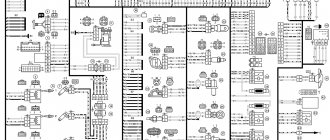
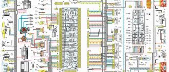
VAZ-2107 diagram: first option
Full size wiring diagram:
Additional designations
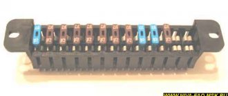
The fuses of the VAZ 2107 car are located as follows:
- taillights and reversing lights;
- electric motor of the heater fan, headlight washer and glass wiper pumps;
- indicator for turning on the rear window heater VAZ 2107;
- direction indicators and hazard warning relays;
- fog lights;
- tachometer, voltmeter;
- control lamps for oil pressure, fluid, fuel level and reserve indicators on the instrument panel, instrument panel lighting;
- cigarette lighter and clock;
- VAZ sound signal;
- interior lighting (up to 2000 there was one lamp on the ceiling, for those manufactured after 2000 there were two lamps on the rear door pillars);
- high beam headlights;
- high beam warning lamp;
- engine compartment lighting and license plate lighting;
- glove compartment lighting;
- right headlight;
- left headlight.
A detailed wiring diagram of the VAZ 2107 will help you understand the intricacy of electrical wiring elements, find the air cover switch or the windshield and headlight wiper relay.
Source
Electrical diagram VAZ-2107 carburetor
Electrical diagram of VAZ 2107, 21074 produced in 1988-2001 with generator 37.3701
- block headlights
- side direction indicators
- accumulator battery
- starter relay
- carburetor electro-pneumatic valve
- carburetor microswitch
- generator 37.3701
- gearmotors for headlight cleaners *
- Fan motor switch sensor
- engine cooling fan motor
- sound signals
- distributor
- spark plug
- starter
- coolant temperature gauge sensor
- engine compartment lamp
- low oil pressure warning sensor
- low brake fluid level indicator sensor
- windshield wiper motor
- carburetor electro-pneumatic valve control unit
- ignition coil
- headlight washer pump motor *
- windshield washer pump motor
- mounting block
- windshield wiper relay
- hazard warning and direction indicator relay
- brake light switch
- reverse light switch
- ignition relay
- ignition switch
- three lever switch
- hazard switch
- socket for portable lamp**
- heater fan switch
- additional resistor for the electric motor of the heater (stove)
- rear window heating indicator lamp
- low brake fluid level warning lamp
- signaling unit
- heater fan electric motor
- glove compartment lamp
- light switches on the front door pillars
- switches for warning lights of open front doors ***
- front door open warning lights ***
- connection block
- cigarette lighter
- watch
- instrument light switch
- diode for checking the serviceability of the low brake fluid level indicator lamp
- fuel level indicator
- fuel reserve indicator lamp
- speedometer
- turn signal indicator lamp
- carburetor choke indicator lamp
- battery charge indicator lamp
- carburetor choke warning switch
- instrument cluster
- econometrician
- light switches on the rear door pillars
- coolant temperature gauge
- tachometer
- indicator lamp for parking brake activation (“handbrake”)
- low oil pressure warning lamp
- high beam indicator lamp
- indicator lamp for turning on external lighting
- voltmeter
- Parking brake indicator switch (“handbrake”)
- outdoor light switch
- rear window heating switch with backlight
- rear fog light switch with on/off indicator *
- fog light circuit fuse
- lampshade ****
- tail lights
- level indicator and fuel reserve sensor
- connectors for connecting to the rear window heating element *
- license plate lights 2107
Wiring diagram VAZ-2107 carburetor - full view:
Underhood wiring
The main part of the electrical wiring is located in the engine compartment, where the main elements, electronic and mechanical sensors of the car are located. A significant number of wires reduce the overall aesthetic appearance of the motor, surrounded by multiple cables. For convenient maintenance of the mechanical components of the engine, the manufacturer places the wiring in a plastic braid, preventing it from rubbing against metal elements of the body and hiding it in body cavities out of sight so that it does not distract attention from the power unit.
Under the hood, electrical wiring provides connection to the main elements of the power unit
Under the hood, the engine contains many auxiliary elements that consume or generate electrical energy, such as a starter, generator, and sensors. All devices are connected to each other in a certain way and in the order shown on the electrical diagram. The wires are secured in a safe and inconspicuous place, which prevents them from wrapping around moving parts of the chassis and motor.
Grounding wires are located inside the engine compartment, a tight connection of which is only permissible on a smooth metal surface. A reliable grounding contact through the car body provides a single circuit of reverse current from the negative terminal of the battery, which is the “ground” of the vehicle. The bundled cables from the sensors are placed in a protective casing that provides insulation from heat, liquids and radio interference.
The wiring system located in the engine compartment includes:
- battery;
- starter;
- generator;
- ignition module;
- high-voltage wires and spark plugs;
- numerous sensors.
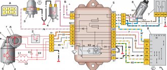
Mounting block connection diagram
P1 — relay for turning on the heated rear window; P2 - relay for turning on the headlight cleaners and washer; P3 - relay for turning on sound signals; P4 - relay for switching on the electric motor of the engine cooling system fan; P5 - headlight high beam relay; P6 - low beam headlight relay; A - the order of conditional numbering of plugs in the mounting block blocks. The outer number with the letter “Ш” in the plug designation is the block number, and the inner number is the conventional number of the plug.
Conventional numbering of plugs in blocks
Additionally, to repair or tune a VAZ, you will need to know the serial numbers of the plugs in the blocks. The electrical diagram of the VAZ 21074 gives the following designations:
- Headlights, windshield and headlight wipers, power supply valve control unit, windshield wiper relay.
- Mounting block and three-lever switch.
- Signal and turn signals.
- Rear block lights.
- Alarm switch.
Schemes of individual blocks of the seven
Power supply system
Power plant starting system
1 - starter; 2 - relay; 3 — ignition switch; 4 - battery
Ignition system
1 - generator; 2 — ignition switch; 3 - distributor; 4 - breaker; 5 — candles; 6 - coil; 7 - battery
Contactless ignition system
External and internal lighting
Windshield wipers and washers
1 — electric motors of the windshield wiper; 2 — washer motor; 3 — mounting block; 4 — ignition switch; 5 - washer switch
Cooling Fan
1 — fan electric motor; 2 - sensor; 3 — mounting block; 4 - ignition relay; 5 - ignition switch.
Carburetor engine
The operation of an engine with a carburetor has a classic scheme:
- When the ignition key is turned to the "Starter" position, the electronic system supplies power to it.
- The generator starts working.
- The generator transmits electric current to the coil. It is used to produce high-voltage currents. Low voltage currents are supplied to the coil. Passing through the module, they are transformed into high-voltage ones and transmitted via a high-voltage wire to the distributor.
- Using high-voltage currents, the distributor drive rotates the crankshaft of the power unit. He closes the contacts in order of priority and delivers an electric discharge to the spark plugs.
The principle of operation is reflected in the electrical circuit of an engine with a carburetor.
Classic wiring diagram - carburetor
Classic ignition
The contact system includes the following elements:
- switch;
- coil;
- distributor;
- high voltage wires;
- candles.
Thanks to the distributor, the circuit of the primary winding of the ignition module is interrupted, and then the high-voltage current is distributed in the required sequence to the spark plugs. With the help of a coil, low voltage current is converted into high voltage current. The spark plugs ignite the fuel mixture in the engine cylinders.
Classic ignition system
If the engine does not start when you turn the ignition key, the reason may be as follows:
- An open circuit between the generator and the coil. In this case, you need to check all contacts and the integrity of the electrical wiring.
- The coil is faulty. It can be checked using a spark: remove the wire from the distributor and touch the metal part. If a spark appears during operation of the power unit, it means the module is working.
- A break in the electrical circuit between the distributor and the spark plugs. In this case, you need to check inside the distributor cover, the slider located there, and the high voltage wiring connecting the distributor cover to the spark plugs.
After identifying and eliminating a malfunction in the carburetor, the engine should start without problems if the other components of the car are working properly.
Electronic ignition
Some VAZ 2107 models that were produced after 1987 had a contactless ignition system installed. Although the car was more expensive, it was in demand. The innovation was that an electronic switch was installed between the distributor and the coil.
The contactless ignition system includes:
- switch;
- ignition switch;
- coil;
- distributor sensor;
- high voltage wires;
- candles.
Non-contact ignition system
Using a distributor sensor, control signals are transmitted to the switch to generate a spark and high-voltage current pulses are distributed across the spark plugs. The function of the switch is to convert control pulses from the contactless sensor into a pulse current that is supplied to the primary winding of the coil. Thus, it improves spark formation if the engine runs on a lean fuel mixture.
Wires for connecting electrical appliances
| Connection type | Section, mm2 | Insulation color |
| Negative terminal of the battery - vehicle ground (body, engine) | 16 | Black |
| Starter positive terminal - battery | 16 | Red |
| Positive contact of the generator - plus battery | 6 | Black |
| Generator - black connector | 6 | Black |
| Terminal on the generator “30” – white MB block | 4 | Pink |
| Starter connector “50” – starter relay | 4 | Red |
| Starter Start Relay - Black Connector | 4 | Brown |
| Ignition switch relay - black connector | 4 | Blue |
| Ignition switch output “50” – blue connector | 4 | Red |
| Ignition switch connector “30” – green connector | 4 | Pink |
| Right headlight plug - ground | 2,5 | Black |
| Left headlight plug - blue connector | 2,5 | Green, gray |
| Generator output “15” – yellow connector | 2,5 | Orange |
| Right headlight connector - ground | 2,5 | Black |
| Left headlight connector - white connector | 2,5 | Green |
| Radiator fan - ground | 2,5 | Black |
| Radiator Fan - Red Connector | 2,5 | Blue |
| Ignition switch output “30/1” – ignition switch relay | 2,5 | Brown |
| Ignition switch contact “15” – single-pin connector | 2,5 | Blue |
| Right headlight - black connector | 2,5 | Grey |
| Ignition switch connector “INT” – black connector | 2,5 | Black |
| Six-pin block of the steering column switch - “ground” | 2,5 | Black |
| Two-pin block of the steering column switch - glove box illumination lamp | 1,5 | Black |
| Glove compartment light - cigarette lighter | 1,5 | Black |
| Cigarette lighter - blue block connector | 1,5 | Blue, red |
| Rear window defroster - white connector | 1,5 | Grey |
Useful: Pinout, connection diagram and checking the VAZ ignition coil
What could happen?
In order to identify faults as quickly and practically accurately as possible, the car owner must have basic knowledge of both the contactless and classic VAZ circuits. As a rule, there are 2 states of electronics that force car owners to immediately contact the nearest service station:
- the vehicle simply does not move;
- movement is carried out, but such phenomena as a short circuit, lack of heating of the rear window of the VAZ 2107, non-working windows, etc. occur.
Any check begins with a visual inspection, however, during such a check, problems in the VAZ 21074 can only be checked by specialists. In carburetor cars, special attention should be paid to the ignition coil, spark plugs and distributor.
However, do not forget about the VAZ 2107 engine compartment wiring diagram. In the case of an injection version of the car, the failure is most often provoked by the ECM, which is responsible for the correct response of sensor signals.
Often, an interactive circuit of electrical equipment fails due to the banal burning of contacts in the ignition system. Fixing the problem is very easy! And then the VAZ electrical circuit will work again without failures. However, if there are even slight doubts about the correctness of the repair, you should definitely seek help from a specialist.
Car wiring diagram
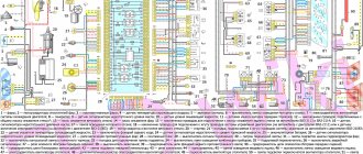
1 – radiator fan drive motor; 2 – relay and fuse block (mounting block); idle speed sensor; 4 – engine control unit; 5 – potentiometer; 6 – set of spark plugs; 7 – ignition control unit; 8 – electronic crankshaft sensor; 9 – electric fuel pump; 10 – tachometer 2107; 11 – lamp for monitoring the health of electronic systems; 12 – ignition system control relay; 13 – speed sensor; 14 – diagnostic connector; 15 – set of injectors; 16 – adsorber solenoid valve; 17, 18, 19 – fuse block protecting the injection system circuits; 21 – electronic fuel pump control relay; 22 – electronic relay for controlling the intake pipe heating system; 23 – intake pipe heating system; 24 – fuse protecting the heater circuit; 25 – electronic oxygen level sensor; 26 – cooling system temperature control sensor; 27 – electronic air damper sensor; 28 – air temperature sensor; 29 – pressure control sensor.
Summary
Overall, the car turned out to be of good quality, which allowed it to remain on the factory assembly line until 2012. Among the features of this attractiveness are low price, the possibility of increasing the interior, ease of maintenance and availability of spare parts.
Similar materials
Names such as the Paris-Dakar Rally and Mitsubishi Pajero are inextricably linked. Of course, after all, behind the wheel of this Japanese SUV, different racers won 12 victories.
Many car owners are thinking about how they can tune Dodge Caravan headlights, because now lensed designs of excellent quality are widespread.
The absence of fog lights on a modern car significantly worsens its safety in conditions of poor visibility. On Kalina cars the manufacturer already.
Model 3110 of the Gorky Automobile Plant was launched into production in 1997 and was conceived as a more modern and improved solution, comparable to the configuration.
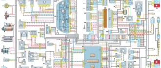
Fuse and relay diagram 2107
On newer “sevens” a block with 17 fuses and 6 relays is installed. VAZ 2107 fuses on the “new” unit protect the following electrical circuits and devices:
- Reversing lamps, heater fan, rear window defroster warning lamp and relay, rear wiper motor and rear washer pump.
- Electric motor for front wipers.
- Reserve socket.
- Reserve socket.
- Power supply for heated rear window.
- Clock, cigarette lighter, power socket “carrying”.
- Signal and radiator fan.
- Turn signal lamps in emergency mode.
- “Fog lights” and a relay that regulates the voltage of the on-board network.
- Instrument panel lamps.
- Brake light bulbs.
- Right high beam headlight.
- Left high beam headlight, high beam warning lamp.
- Side lights (rear right, front left), license plate and engine compartment lighting.
- Side lights (rear left, front right), glove compartment and cigarette lighter lamps.
- Low beam (right lamp).
- Low beam (left lamp).
The block relays perform the following functions:
- Heated rear window relay.
- Headlight cleaner and washer relay.
- Signal relay.
- Cooling system electric fan relay.
- High beam relay.
- Low beam relay.
The fuse block of the VAZ 2107 (injector) is no different from the block on the carburetor “seven”. Injection models are simply equipped with an additional relay and fuse box installed in the cabin under the glove compartment. The block includes three relays - the “main” relay, the fuel pump relay and the fan relay.
Features of electrical equipment maintenance and replacement of wiring VAZ 2106
Correctly laid wiring around the perimeter of the cabin and under the hood does not require special attention and maintenance. But, after repair work, the cable may be pinched, its insulation may be damaged, which will lead to a short circuit. Poor contact will lead to heating of the cable and melting of the insulation. A similar result will occur if instruments and sensors are installed incorrectly.
A long period of vehicle operation affects the condition of the wire insulation, which becomes hard and brittle, especially under the influence of significant heat in the engine compartment. Damage caused by damaged wires is not easy to find. If the damage is in the public domain without braiding, repairs are carried out without dismantling the wires.
When replacing one wire, you should label the ends of the wires located in the blocks, making a connection drawing if necessary.
Main stages of wiring replacement:
- new wiring harness for the VAZ 2106 model;
- disconnected battery from the vehicle network;
- disassembly of the instrument panel;
- torpedo disassembly;
- removing seats;
- removal of the noise-insulating coating for convenient access to the wiring harness;
- clean out corrosion that may cause poor contact;
- It is not recommended to leave exposed wires at the end of the work.
The wiring replacement procedure should not be carried out without an electrical diagram for connecting the devices to avoid confusion during installation work.
When replacing a single wire, a new one should be of the same color and size. After replacement, you should test the corrected wire with a tester connected to the nearest connectors on both sides.
Precautionary measures
Before performing work, you should disconnect the battery and insulate the sharp edges of the technological holes in the car body in places where the wires will pass to prevent a short circuit.