Detailed color diagrams of the VAZ 2114 wiring (carburetor, injector) are provided with a description of the electrical equipment for various modifications.
The information is intended for self-repair of cars. Many electrical circuits are divided into several sections for ease of viewing via a computer or smartphone; there are also circuits in the form of one picture with a description of the elements - for printing on a printer. The VAZ 2114 (Samara-2) car is built on the VAZ 21093 platform and is an improved version of it. The first prototype of the hatchback was assembled back in 2000. A year later, the Volzhsky Automobile Plant produced the first pilot batch of 50 VAZ-2114 cars, and in the same 2001 the hatchback was first introduced to the market. The interior features a new instrument panel, a new steering wheel, an adjustable steering column, power windows and a new heater. Years of production 2114: 2001—2013
The fourteenth model was previously equipped with a 1.5 liter eight-valve engine, borrowed from the VAZ 2111 model with an injector. A little later it was replaced by the VAZ 11183-1000 version, which complies with the Euro-3 standard. The VAZ 2114 injector received a more powerful engine, and this is one of the reasons that the wiring of the 2114 has also changed.
A wiring harness has been added for connecting to the electronic switch. A harness has also appeared for connecting to the ignition module terminal.
Replacing high-voltage wires will require additional attention, because the connection procedure depends on the year of manufacture of the car. Until 2004, 4-pin ignition modules were installed, and after that - 3-pin. Connecting the adsorber valve to the injection system controller also provided another additional element. An adsorber is an electromechanical device used for ventilation and removal of condensate in a gas tank. Complications also affected the interior part. The dashboard received improvements in the form of the appearance of a BC (on-board computer), a new instrument panel and a change in the position of the glove compartment.
Car modifications 2114
VAZ-21140 . Modification with an 8-valve injection engine VAZ-2111, 1.5 liters and 77 horsepower. Serial production from 2003 to 2007
VAZ-21144 . Modification with an 8-valve VAZ-21114 engine, 1.6 liters and 81.6 horsepower. Years of serial production: 2007-2013.
VAZ-211440 . Another modification released in 2007, it was equipped with a VAZ-11183 engine with a volume of 1.6 liters and a power of 82 horsepower. The car was discontinued in 2013.
VAZ-211440-24 . Released in 2009, a modification with an injection 16-valve VAZ-21124 engine with a volume of 1.6 liters and a power of 89.1 horsepower. Discontinued in 2013.
VAZ-211440-26 . Modification with a 16-valve injection engine VAZ-21126, which complies with the Euro-3 environmental standard, with a volume of 1.6 liters and a power of 98 hp. The car was produced from 2010 to 2013.
AvtoVAZ stopped producing Lada Samara
AvtoVAZ stopped producing Lada Samara
27 November, Wednesday,
Whatever you were, that's how you remain - this look is perfectly suited for the four-wheeled miracle of technology called Lada Samara from AvtoVAZ. The Russian automaker AvtoVAZ has finally announced the cessation of production of another outdated model of the car - Lada. “Fourteenth” will leave the assembly line in December. AvtoVAZ says nothing about the burial ceremony; may the old Lada Samara rest in peace.
“Instead of the Lada Samara hatchback, starting this year, the auto giant will begin producing the Lada Granta hatchback in Izhevsk,” the automaker’s press service reported about this event. Production of the Lada Samara will end with a five-door hatchback. Other versions of the car left the assembly line earlier.
Thus, production of the Lada Samara sedan (VAZ-2115) was discontinued at the end of the year. And production of the three-door hatchback Lada Samara (VAZ-2113) stopped in September of this year. Completion of the assembly of this model will be the next step towards a complete update of the model range of the domestic company. But on the roads in the regions, these iron “horses” will delight the eye of a passerby or a motorist passing by for a long time.
It should be noted that at the end of last year, sales of Lada Samara in Russia amounted to 67,971 cars. In October of this year, sales of the model fell by 15% compared to the same period last year, to 3,661 cars. In total, since the beginning of the year, Samara sales have decreased by 36%, to 35,143 cars, PRIME reports.
AvtoVAZ is one of the largest enterprises in the automotive industry in Eastern Europe. Production capacities allow the production of over 800 thousand cars per year. The automaker produced 718 thousand cars in a year. Lada sales decreased by 4.1% compared to the previous year - to 608.2 thousand units.
The updated Lada Priora should hit the market in the fall of this year. In September, budget versions of the new generation Lada Kalina went on sale. Next year, the Lada Granta is expected to appear in a hatchback body. Also, the Tolyatti Automobile Plant may release a crossover based on the Lada Kalina and a hybrid version of one of its models.
R93 – Auto portal of the Krasnodar region: Auto news
Wiring diagram VAZ-2114 for old models
Electrical diagram of car 2114: 1 – headlight; 2 [Installed on a part of the car] – fog lamp; 3 – ambient temperature sensor; 4 – electric engine radiator fan; 5 – block for connection to the wiring harness of the engine control system; 6 – engine compartment lamp switch; 7 [Installed on a part of the car] – reserve block for connecting an audio signal with one terminal (the negative terminal is connected to the body); 8 – sound signal; 9 – liquid level sensor in the windshield washer reservoir; 10 [Installed on a part of the car] – brake pad wear sensor; 11 – low oil level sensor; 12 – generator; 13 [Installed on a part of the car] – engine compartment lamp; 14 – temperature indicator sensor; 15 – starter; 16 – battery; 17 [Installed on a part of the car] – relay for turning on fog lights; 18 – coolant level sensor in the expansion tank; 19 – sensor of insufficient brake fluid level; 20 – reverse light switch; 21 – windshield wiper gear motor; 22 – emergency oil pressure sensor; 23 – rear window washer electric pump; 24 – electric pump for windshield washer; 25 – instrument panel; 26 – mounting block of fuses and relays; 27 – brake signal switch; 28 – ignition relay; 29 - ignition switch (lock); 30 – glove box lighting lamp; 31 – switch for the glove compartment lighting lamp; 32 – rear window heating switch; 33 – rear fog light switch; 34 [Installed on a part of the car] – fog light switch; 35 – combined switch for side lights and headlights; 36 – alarm switch; 37 – steering column switches; 38 – brightness control for instrument lighting; 39 – illumination lamp for the headlight hydraulic adjustment control handle; 40 – socket for connecting a portable lamp; 41 – side direction indicator; 42 – interior lighting switch (front door open sensor); 43 – interior lamp; 44 – electric fan of the ventilation and heating system; 45 – additional resistor of the electric fan of the ventilation and heating system; 46 – switch for operating modes of the electric fan of the ventilation and heating system; 47 – illumination lamp for the handle of the operating mode switch of the electric fan of the ventilation and heating system; 48 – backlight lamp for the heater control unit; 49 – display unit of the on-board control system; 50 [Installed on part of the car] – trip computer; 51 – interior lighting switch (rear door open sensor); 52 [Installed on a part of the car] – block for connecting a clock; 53 – fuel module; 54 – ashtray illumination lamp; 55 – cigarette lighter; 56 – interior lamp; 57 – switch for the parking brake warning lamp; 58 – rear light; 59 – license plate light; 60 – additional brake light; 61 – heating element for heating the rear window; 62 – rear window wiper gear motor; A – pin numbers in the connecting blocks.
Causes of breakdowns
The most common reasons for node failure:
- the narrowest point in the entire structure is the elastic board;
- in second place, banal burnout or mechanical damage to light bulbs;
- the third reason is a problem with the fuse or relay;
- oxidation of contacts;
- broken wiring.
First of all, it makes sense to check those elements that do not require removing the entire headlight (for example, fuses, relays). Then check the quality of the connections, the presence of oxidation and the voltage supply level to the illuminator. The last step is to disassemble the taillight, remove and inspect the board.
VAZ-2114 diagram (second option)
Electrical diagram of VAZ-2114 cars (without engine control system):
1 – headlights; 2 – fog lights; 3 – air temperature sensor; 4 – electric motor of the engine cooling system fan; 5 – blocks connected to the wiring harness of the ignition system; 6 – engine compartment lamp switch; 7 – block for connection to a single-wire type audio signal; 8 – sound signal; 9 – washer fluid level sensor; 10 – front brake pad wear sensor; 11 – oil level sensor; 12 – generator; 13 – engine compartment lamp; 14 – coolant temperature indicator sensor; 15 – starter; 16 – battery; 17 – relay for turning on fog lights; 18 – coolant level sensor; 19 – brake fluid level sensor; 20 – reverse light switch; 21 – windshield wiper gearmotor; 22 – oil pressure warning lamp sensor; 23 – block for connecting to the rear window washer electric motor; 24 – electric motor for windshield washer; 25 – instrument cluster; 26 – mounting block 2114; 27 – brake light switch; 28 – ignition relay; 29 – ignition switch; 30 – glove box lighting lamp; 31 – glove box lighting switch; 32 – rear window heating element switch; 33 – rear fog light switch; 34 – fog lamp switch; 35 – switch for external lighting lamps; 36 – alarm switch; 37 – steering column switches; 38 – switch for instrument lighting lamps; 39 – illumination lamp for the headlight hydrocorrector scale; 40 – plug socket for a portable lamp; 41 – side direction indicators; 42 – lamp switch on the front door pillars; 43 – canopy for individual interior lighting; 44 – heater fan electric motor; 45 – additional resistor of the heater electric motor; 46 – heater fan switch; 47 – heater switch illumination lamp; 48 – backlight lamp for heater levers; 49 – on-board control system unit; 50 – trip computer; 51 – lamp switch on the rear door pillars; 52 – block for connecting the wiring harness of the engine control system; 53 – electric fuel pump and gasoline quantity sensor; 54 – front ashtray illumination lamp; 55 – cigarette lighter 2114; 56 – trunk lighting lamp; 57 – trunk light switch; 58 – interior lamp; 59 – parking brake warning lamp switch; 60 – rear external lights; 61 – rear internal lights; 62 – block for connection to the rear window heating element; 63 – license plate lights; 64 – additional brake signal located in the spoiler.
Conventional numbering of plugs in blocks:
- A – headlight blocks;
- B – electric fuel pump block;
- C – blocks of the mounting block, ignition switch, windshield wiper gearmotor;
- D – blocks for the interior lighting.
Useful: VAZ tachometer connection diagram
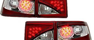
What and how can you change the standard lights?
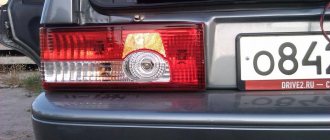
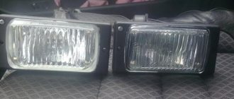
The easiest way is to change the appearance of your car - replacing the light fixtures with more original ones. The range of flashlights for the VAZ 2114, of course, is not particularly wide, but there is plenty to choose from. And the simple way is because all tuning comes down to “removing the standard ones, installing the purchased ones.” Let's wander around the shops and see what we can find for our VAZ 2114.
Osvar flashlights are the most popular option among car enthusiasts. They are relatively inexpensive and finding them is not a problem. The only thing is that the manufacturer uses ordinary light bulbs in it, but if desired, you can replace them with LED ones yourself. Although for most car owners this is not relevant.
Tail light “Osvar” on VAZ 2114
Skyline style . Also a “lamp” option, but it looks completely different.
Tail light Skyline style for VAZ 2114
ProSport RS-02020 . This is already an LED option. True, the light bulbs responsible for the different signals in them are clearly not in their places, which may not please other road users, and the traffic police inspector will definitely not understand you.
Tail light ProSport RS-02020
ProSport RS-02020-T . The same “ProSport” with mixed up signals, but with tinted windows. A real gift to the traffic police!
Tail light ProSport RS-02020 with tinted glass
ProSport RS-07490 . Option with light bulbs. Same manufacturer, same misunderstanding - the turn signal is located between the marker and the brake light. You can't make it up on purpose.
Tail light ProSport RS-07490
"Zigzag" 0013L . This LED miracle is offered by manufacturers from Togliatti, the birthplace of the VAZ car. Here at least the signals are more or less in place.
Tail light "Zigzag" 0013L
We'll finish our shopping trip here, although there are still many miracles there. Just watch a short video about a flashlight with red turn signals and move on to the next point.
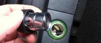
How to remove tail lights
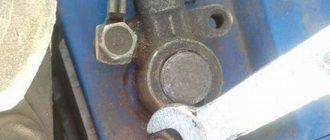
It's time to figure out how to remove the stock lights to install new ones. To work, you will need an 8 socket wrench with an extension and a Phillips screwdriver. We open the trunk door, use a Phillips screwdriver to dismantle part of the upholstery so that, by bending it, you can gain access to the entire rear part of the lamp.
The upholstery is attached to the body using self-tapping screws
We find 4 nuts around the perimeter of the light fixture and unscrew them with a wrench
The lamp is secured with four nuts
Carefully remove the connector by pulling it towards the central axle of the car. We don’t swing it, we just pull it, trying not to twist it!
Removing the power supply
Pull the light from the outside of the car toward you and remove it.
Now the lamp can be removed
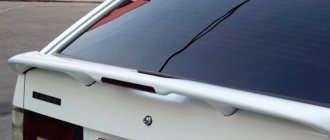
We install the new light fixture in the reverse order.
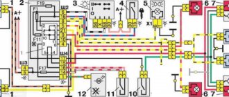
Wiring diagram VAZ-2114 new models
The updated engine has a new injection scheme, so it was necessary to use some new devices, as well as replace the ignition coil with a more efficient one and adapted to Euro 3 conditions. In order to comply with them, the engine had to minimize the amount of CO at start-up. And for this it was necessary to lean the mixture. Since a lean mixture ignites worse, it needed a more powerful spark to spark. This explains the use of a coil of increased power.
- block headlights;
- gearmotors for headlight cleaners*;
- fog lights*;
- ambient temperature sensor;
- sound signals;
- engine compartment light switch;
- engine cooling fan electric motor;
- generator VAZ-2114;
- low oil level indicator sensor;
- washer fluid level sensor;
- front brake pad wear sensor;
- wire ends connected to the common windshield washer pump**;
- windshield washer pump;
- headlight washer pump*;
- wire ends for connecting to the rear window washer pump on VAZ-2113 and VAZ-2114 cars;
- low oil pressure indicator sensor;
- engine compartment lamp;
- wire lug for connecting to the engine management system wiring harness;
- windshield wiper gear motor;
- starter VAZ-2114;
- block connected to the wiring harness of the ignition system on carburetor cars;
- coolant temperature indicator sensor;
- reverse light switch;
- low brake fluid level indicator sensor;
- accumulator battery;
- low coolant level indicator sensor;
- relay for turning on fog lights;
- mounting block;
- brake light switch;
- plug socket for a portable lamp;
- hydrocorrector scale illumination lamp;
- parking brake indicator lamp switch;
- block for connecting a backlight lamp;
- switch for instrument lighting lamps;
- Understeering's shifter;
- hazard switch;
- front seat heating element relay;
- ignition switch;
- rear fog lamp circuit fuse;
- front seat heating elements circuit fuse;
- door lock circuit fuse;
- front ashtray illumination lamp;
- ignition relay;
- cigarette lighter VAZ-2114;
- glove box lighting lamp;
- glove compartment light switch;
- heater fan motor;
- additional heater motor resistor;
- heater fan switch;
- heater switch illumination lamp;
- heater lever illumination lamp;
- gear motors for electric windows of the front doors;
- right front door ESP switch (located in the right door);
- gear motors for locking front door locks;
- wires for connecting to the right front speaker;
- gear motors for locking rear doors;
- wires for connecting to the right rear speaker;
- door lock control unit;
- wires for connecting to radio equipment;
- headlight wiper switch*;
- rear window heating element switch;
- rear fog light relay;
- block for connection to the heating element of the right front seat;
- rear fog light switch;
- right front seat heating element switch;
- fog light switch*;
- switch for external lighting lamps;
- left front seat heating element switch;
- block for connection to the heating element of the left front seat;
- wires for connecting to the left front speaker;
- left front door power window switch (located in the left door);
- right front door power window switch (located in the left door);
- wires for connecting to the left rear speaker;
- side direction indicators;
- dome light switches on the front door pillars;
- dome light switches on the rear door pillars;
- lampshade VAZ 2114;
- individual interior lighting lamp;
- block for connecting to the wiring harness of the electric fuel pump;
- trunk light switch;
- instrument cluster;
- trunk light;
- on-board control system display unit;
- trip computer*;
- block for connecting the wiring harness of the engine management system;
- rear exterior lights;
- rear interior lights;
- pads for connecting to the rear window heating element;
- license plate lights;
- additional brake signal located on the spoiler.
Numbering order of plugs in blocks:
A – headlight units and headlight cleaners; B – cigarette lighter; B – mounting block, instrument cluster, ignition switch, windshield wiper and other electrical components (for blocks with a different number of plugs, the numbering order is similar); G – relay for turning on the rear fog light; D – alarm switch; E – electric window motors and door lock motors; F – interior lamp.
In the instrument panel wiring harness, the second ends of the white wires are brought together into one point, which is connected to the instrument lighting switch (except for the white wire, from plug “4” of block “X2” of mounting block 28 to display block 83 of the on-board control system). The second ends of the black wires are also brought together to points connected to ground. The second ends of the yellow wires with a blue stripe are brought together to a point connected to plug “4” of the “X1” block of the mounting block. The second ends of the white wires with a red stripe are brought together to a point connected to plug “10” of the “X4” block of the mounting block. The second ends of the orange wires are brought together to a point connected to plug “3” of the “X4” block of the mounting block.
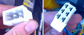
Explanations for the 8-pin injector block: white-red and blue - for the check light bulb, blue-red - ignition, gray - speed sensor, brown-red - tachometer, blue-white - driver's door switch (for the immobilizer), green- red - K-line (may not exist), green - fuel consumption. Next to it is a pink wire - to the fuel level sensor.
See the complete diagram in one file below (click to enlarge):
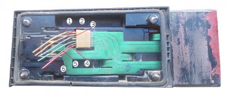
Tail light repair
The most common reason for the failure of a VAZ 2114 rear light is the failure of a flexible printed circuit board or a connector made directly on it with conventional metallization. You can, of course, just buy a new printed circuit board and replace the faulty one with it, but, firstly, for how long?
And secondly, we are not looking for easy ways. So we will try to eliminate this malfunction on our own, at minimal cost and in such a way that it will last forever. Let's start with the connector for connecting the flashlight to the on-board network. It looks something like this:
The connector for connecting the rear light to the on-board network is part of a flexible circuit board and cannot be replaced separately
There are many reasons for this connector to fail. For example, we removed the power supply from the flashlight too often and simply partially erased the traces, which have a very small thickness of copper deposition on the plastic. Another reason is that the conductive paths next to the connector broke due to constant vibration. Well, the most banal thing is that the tracks burned out due to overload or short circuit.
Due to burnout of the conductive tracks of the flexible board, the rear fog lights do not light up
The photo shows a flashlight connector of a different modification, but the meaning of the problem is the same. All these issues can be solved with the help of a soldering iron, mounting wire and a regular six-pin (or more) connector with a mating part.
For repairs you will need this block with a mating part
We clean the connector contacts on the board using a student eraser (not sandpaper - the foil is very thin!) and service them.
You need to tin the tracks very quickly with a well-heated soldering iron. Otherwise, the tracks will simply fall off the substrate.
We solder the wires from the block onto the tracks, not forgetting to mark them, and fill the soldering area with sealant or a hot glue gun.
Mounting block soldered to the rear light board
We cut off the standard power harness block, and in its place we solder the mating part of the new one. We assemble the flashlight, connect it to the on-board network - and check it. If we haven't messed up the wiring of the pads, then everything will work right away with a bang.
What to do if the tracks are burned out or broken? You can get out of this situation as follows. Immediately after the fracture, we clean the protective varnish from the tracks, tin, and solder the block. It will look like this:
You can solder the header anywhere on the flexible board.
You can, of course, limit yourself to this (until next time), but if you spend a little more time and effort, you can make more serious repairs. Flashlights modified in this way will serve faithfully for many years. Such a repair will save you from the eternal problem of contacts of flimsy standard sockets - this is also a very common malfunction of VAZ 2114 headlights.
To implement this idea, in addition to the six-pin block with a mating part (see above), you will need five cartridges from the VAZ 2106 direction indicators and a dozen terminals for them.
You will need 5 such cartridges and 10 terminals for them
We remove the lamps, standard sockets and flexible printed circuit board from the panel. We place the purchased cartridges in the right places on the panel and mark their centers. Special precision is not required here, the main thing is that each lamp shines into its own “window”. We drill holes according to the diameter of the base parts of the cartridges.
Holes for future cartridges
We insert the cartridges into the holes, mark the mounting holes, drill them, and screw in the screws. Now the cartridges are firmly fixed in the panel.
We secure each cartridge with two self-tapping screws
Using a mounting wire with terminals pressed onto it (you can crimp it with ordinary pliers and solder it to be sure), we assemble a circuit that repeats the layout of a standard flexible printed circuit board. To be sure, the terminals can be insulated with heat-shrinkable tubing, but in principle this is not necessary - the panel on which the cartridges are mounted is plastic. We solder our block to the ends of the wires.
This block will connect the rear light to the on-board network
We solder the mating part of the block to the power supply harness of the lights, having first cut off the old one. We solder it, not twist it together. The twist will oxidize in a week, and problems will begin again - sometimes it burns, sometimes it doesn’t. We insulate the solder joint with heat shrink or cotton (black rag) tape. PVC electrical tape is an extremely bad option. It can unfold over time. This kind of isolation is no good.
Everything is ready, you can connect and check
We admire our work for a couple of minutes, insert the lamps, connect them, check them. Is everything working as expected? We assemble the lantern and connect it.
The lantern is in place, all problems are solved for a long time
LED analog P21W
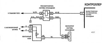
Relays and fuses VAZ 2114
F1 for 10 Amps (A) rear fog lights and rear fog light warning lamp. F2 for 10 A turn signal lamps, turn signal relay, hazard lights, hazard warning lights. F3 7.5 A lamps for interior lighting (both) and trunk, ignition lighting, powertrain control system control lamp, brake lamps, computer, if available. F4 20 A carrier, relay and rear window heating element. F5 20 A horn and its relay, cooling fan. F6 30 A power windows and their relays F7 30 A motor heater, headlight cleaner, windshield washer, cigarette lighter, glove compartment light bulb, rear window heating relay winding. F8 7.5 A right fog lamp. F9 7.5 A left fog lamp. F10 at 7.5 A left side marker, lamp signaling the inclusion of the side light, lamps for illuminating the sign, engine compartment, illumination of switches and instruments, instrument lighting switch. F11 at 7.5 A right side. F12 at 7.5 A right low beam. F13 at 7.5 A left low beam. F14 for 7.5 A left high beam and a light indicating that the high beam headlights are on. F15 at 7.5 A right far. F16 30 A - a light indicating insufficient oil pressure, brake fluid level, engagement of the parking brake, low battery, instrument cluster, relay for monitoring the health of lamps, indication of control systems, reversing lamps, turn indicators and their relays, as well as an alarm if turning mode is turned on, computer, generator excitation winding is turned on at the moment the engine starts.
What to do if the lamps are constantly on?
Some car enthusiasts are faced with the problem of chaotic starting of lamps that turn on regardless of reverse gear or burn in constant mode. Auto mechanics note several reasons for this situation:
- the connection of the power sensor and the wires from the lamps led to a short circuit;
- frayed wire;
- The sensor is stuck in a closed state.
For cars operating on an automatic transmission system or CVT gearbox, breakdowns can be caused by a number of other reasons. Repairing the lighting here will be a little more difficult. This is due to the presence of a gear controller. Therefore, it is safer to contact a specialist workshop.
VAZ-2114 wiring harness diagrams
Instrument panel harness
Glove compartment lighting harness
Front harness (without fog lights)
Rear harness VAZ-2114
Wiper Harness
Additional harness
Connects to the instrument panel, the connector is next to the hood handle. Pink - door lock, permanent plus, fuse hangs next to the hood release handle. White and black - on the door for electric windows, plus during ignition, switched on through a relay and fuse in the mounting block. Also in the photo is the wiring for the radio speakers.
Right door harness
Connects to an additional harness.
Left door harness
Connects to an additional harness.
Seat heating harness
The gray wire is connected to the connector where the additional harness is connected (to the gray wire if there is one), plus when igniting, the relay is attached next to the mounting block and the fuse is located next to the hood handle. The white wire is connected to the additional harness, button illumination.
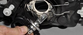
Replacing light bulbs
Now let's replace the rear light bulbs. We lift the trunk and look for a valve in the upholstery located opposite this device.
On the trunk side the lamp is covered with a Velcro flap
We open the valve (it is on Velcro) and observe the back of the flashlight with the power supply connected to it.
Rear part of the lamp VAZ 2114
We pull out the block by pulling it towards the central axis of the machine.
Important! The mating part of the block is a metallization applied to a flexible circuit board. We remove the block carefully, since if the pulling is unsuccessful, the entire board will have to be replaced.
We release the latch located on the side of the lamp that is located closer to the center of the machine, and remove the board along with the lamps.
Removing the board with lamps
We unfold the board with the bulbs facing up and observe the picture shown in the photo in the first section of the article. All lamps are removed in the same way - by turning them counterclockwise. We find the burnt out lamp and replace it with a new one.
Replacing the reverse indicator lamp
Angel eyes
A fairly popular tuning is the use of LEDs to create “angel eyes”. They look quite attractive. To perform optics replacement work you will need the following tools:
1. Resistors. 2. LED. 3. Jars with an outer diameter of 7 centimeters. 4. 9 volt batteries. 5. Plexiglas sticks with a transparent structure.
Headlights for tuning a VAZ 2114 will look quite interesting, for which you need to do the following work:
- First you need to heat the stick until it becomes soft. Thermal deformation is necessary for the stick to become flexible and become a kind of ring.
- After heating, you should take a stick and twist the jar with it. After giving the required shape, it is left to cool. When the stick cools, its shape will not change.
- After hardening, you can trim off the excess ends.
- The two LEDs must be connected in series using a resistor.
- We sand the ends.
- Using a tape measure, make a notch at the same distance around the circumference of the rod. This must be done to ensure uniform lighting.
- The formation of grooves should be done at the ends.
- All LED connections must be isolated.
- The gap in the ring should be covered with foil.
- You must use sealant to secure the ring to the projector. In this case, the notches should face the inside of the projector.
The last step is to connect the system to a power source. The results obtained will be very interesting.
When should the side lights be turned on?
The driver is required to turn on the lights whenever there is poor visibility on the road, as well as when driving through a tunnel.
Conditions for poor visibility include:
- heavy rain/snow;
- fog;
- dusk/predawn.
It is very important to turn on your side lights when driving in fog. At the slightest sign of its appearance (especially in the dark), you need to turn on the dimensions, indicating the boundaries of your own vehicle.
If you are forced to stop on the side of the road in conditions of insufficient visibility, you should definitely turn on the side lights, and in the dark, also turn on the emergency lights. Such actions will protect you and help other road users not to get into a situation where a car suddenly appears out of the fog/darkness in front of them.