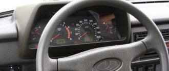
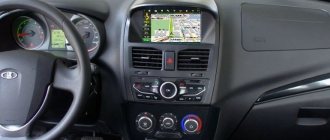
The VAZ dashboard has an electronic combination, as well as conveniently located backlighting. The lamps are illuminated from the inside, which is a feature of the 14th Lada.
Thanks to the instrument panel, the driver knows all the information he needs, what is the reserve and consumption of gasoline, mileage, etc. The panel should be easy to operate with a clear overview of the icons, scale, gauge and indicators.
What is the state of the automobile systems responsible for road safety, driving speed, the rest of the way to the intended object, rational engine operation and gasoline consumption, the operation of the suspension and electrical equipment - all this should be reflected on the control panel.
Signal lamps and equipment control devices must be required on the panel. There are a total of 19 symbols on the panel.
Control panel design
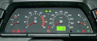
The main symbols include the fuel level, speedometer, tachometer, and sensors for cooling the liquid. The temperature sensor is indicated by an arrow on the left side of the panel.
If the sensor needle is in the zone from 105 to 130 degrees, you should immediately stop the car and wait until the engine cools down, otherwise the engine will simply boil. The tachometer is presented in the form of a dial scale on the instrument panel.
Engine speeds from 2 to 5.5 thousand per minute are considered the norm. If the needle falls into the red zone, fuel consumption may increase sharply, and the load on engine parts will become greater. The panel must have a speedometer.
With its help, the driver controls the speed, which directly affects road safety. The speedometer is an important part and should show clear data.
The sensor is located in the form of an arrow, which shows the fuel level in the car tank and is usually located on the right side of the device. Although it will not measure exact data about gasoline, you can find out the approximate fuel remaining at any time.
The panel design is quite simple, and at the same time highly informative; removing it is not difficult.
Using the panel, you can get a lot of useful information, namely: - is the condition of the VAZ safe at the time of movement - what is the speed, revolutions, availability of gasoline - what is the condition of the car's spare parts - other information, date and time.
With the help of sensors and meters, the driver is aware of all the information about his car. The VAZ tidy is made of plastic, which gives it an aesthetic appearance; it does not creak at all, unlike the same nine.
The device is simple, easy to disassemble and assemble.
Where is the mass located?
When operating a car, it is important to know all the places where the mass of the VAZ 2114 engine is located. If a malfunction occurs in this direction, you can quickly detect the source of the problem and eliminate it accordingly
So, where is the mass of the ECU for the VAZ 2114? Let's try to understand this issue.
Where is the mass located on the VAZ 2114:
Battery weight.
Battery weight of VAZ 2114
The negative battery branch consists of branches of wires of two types - thin and thick wire. The battery negative is directed to the motor housing using a thick wire. As a result of poor contact fastening, the charge will be supplied in a small volume, as a result, the starter will not be able to develop sufficient power, and the ECM will therefore fail, because it receives the required mass from the engine.
In order to check the negative charge connections between the battery and the engine, it is necessary to check the reliability of the two nuts, so you first need to loosen the nut from the outside and tighten the nut from the inside, and then screw the nut back on from the outside.
A thin negative wire is connected to the car body next to the battery. It plays the role of an energy source necessary for all consumers equipped in the car. To check, you also need to make sure the degree of tension of the nut both with the body and with the battery terminal.
Weight of ECM VAZ 2114.
Weight of engines VAZ 2114
Samar engines with a volume of 1.5 liters take weight from the engine body, from the mounting plugs, which are located to the right of the cylinder head.
Samar engines with a volume of 1.6 liters, or 1.5 liters equipped with a new type of ECM, take weight from a welded stud. The pin is attached directly to the metal body of the instrument panel near the floor tunnel in the area under the ashtray. When assembled at the manufacturer's factory, the stud is usually poorly secured and painted, as a result, during operation of the machine it can become completely loose, as a result, when the ventilation device is turned on, the electrical voltage of the system will drop, and the following devices will react accordingly: mass air flow sensor, air metering sensor, air pressure sensor.
Instrument panel weight.
Weight of the VAZ 2114 dashboard
In this version, there is a connection between the torpedo harness, the circuit from the mounting relay and fuse block, and the rear harness. This connection is located under the steering shaft mount. If the connection of this mount is not of good quality, problems may arise in the operation of the dashboard readings when the main energy consumers are turned on, for example: turn signals, headlights, etc.
Electric motor heater weight
This ground connection is located under the instrument panel on the left side of the heater housing.
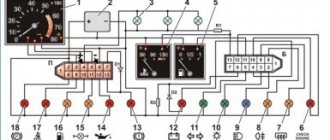
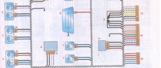
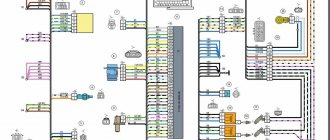
VAZ 2114 instrument panel pinout
Electrical connection diagram for the VAZ 2114 instrument panel (Click on the picture to enlarge)
- – rear window heating switch;
- – rear fog lamp switch;
- – switch for headlights and direction indicators;
- – mounting block;
- – windshield wiper switch;
- – fog light switch;
- – display unit of the on-board control system;
- – block of the instrument panel harness to the additional harness;
- – instrument cluster;
- – instrument panel harness connector to the on-board computer harness;
- – block of the instrument panel harness to the ignition system harness;
- – block of the instrument panel harness to the side door harness;
- – fuse 16 A;
- – fuse 16 A;
- – ignition switch;
- – lighting switch;
- – heater electric motor;
- – additional resistance of the heater electric motor;
- – ignition switch unloading relay;
- – rear fog lights relay;
- - starter relay;
- – socket for connecting a portable lamp;
- – cigarette lighter;
- – block of the instrument panel harness to the wiring harness of the glove box lighting lamp;
- – illuminator;
- – illuminator;
- – illuminator;
- – heater switch;
- – instrument lighting regulator with rheostat;
- – brake signal switch;
- – horn switch;
- – hazard warning switch;
- – backlight lamp for the heater control panel;
- – fuse 16 A;
- – seat heating relay;
The panel pinout is a diagram, but the diagram described in words seems easier for many. The contacts located on the instrument panel, and there are only 26 of them, are responsible for the operation of the indicators on the panel itself.
If a plus is applied, then each of the contacts shows information and the state in which the car is currently located. The panel is equipped with sensors and signal indicators, and the panel is controlled using an electronic unit.
Inside the panel there are two pads - red and white. Fuses, inputs and outputs, controllers are connected to a specific plug. If the sensors fail, they need to be replaced.
You can check the serviceability of the wiring by disassembling the instrument panel. Oxidized or damaged wires must be replaced. Indicator lights may fail. Burnt out light bulbs must be replaced with new ones.
A faulty lamp sensor must also be replaced. The contact between the board and the lamp must be well connected, otherwise the ends of the contacts should be cleaned, bent, and if necessary, replace the lamp socket.
If the backlight stops working or the radio is faulty, the fuse must be replaced. Maybe the damage is not in the fuse, but in the wiring, which also requires replacement.
A short circuit in the fuse can also damage it.
Schetmash
The “Schetmash” instrument panel was set to “fourteenth” from the first days of production. Subsequently, VDO devices began to be installed on the car. But even among the cars of recent years, there are sometimes cars with this panel.
For this device, the pinout of the VAZ 2114 instrument panel is as follows:
For white block (X1):
- 1 black – weight per body;
- 2 purple - brown - to the tachometer (input from the ECU, low voltage);
- 3 yellow – tachometer (input from the ignition module, high-voltage);
- 4 purple - white - fuse F3;
- 5 white-green – antifreeze level sensor;
- 6 brown – fuse F10;
- 7 reserve;
- 8 purple - white - Check Engine;
- 9 pink - black - to the electronic control unit;
- 10 orange – sensor indicating the gasoline level;
- 11 brown-blue - to the hand brake;
- 12 white-brown - to output D on the generator;
- 13 blue-blue – engine oil level sensor.
For the red chip (X2):
- 1 purple-blue - to the outside air temperature sensor;
- 2 orange - fuse F16;
- 3 black - weight per body;
- 4 white — dashboard lighting;
- 5 blue - to the right direction indicator;
- 6 black and blue - to the left turn indicator;
- 7 pink-blue - brake fluid level sensor;
- 8 brown - leads to the on-board computer;
- 9 yellow-gray - sensor indicating speed;
- 10 pink - fuel level sensor;
- 11 black-green - fuse F14;
- 12 – to the alarm;
- 13 purple - terminal 50 on the ignition switch.
As can be seen from the description, the location of certain connectors on the instrument panels is slightly different. When replacing the device with a more modern one, or vice versa, the motorist may experience some connection difficulties. Therefore, if you have no experience in auto electrics, it is better to entrust such tuning to specialists.
Tuning the dashboard of Lada 2114
To make their car distinctive, many motorists resort to tuning.
Although this is a troublesome task, it is worth it. Everyone strives to make the salon spectacular and cozy. The dashboard is a favorite place for tuning.
Backlight tuning
To make the panel devices look stylish and modern, they can be modernized. Let's look at how backlight tuning is done.
You can improve the appearance of a vehicle yourself, since the process is not at all complicated.
Everything you need for tuning:
- panel disassembly;
- removing the shield;
- tune the necessary parts;
- put in place.
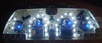
The first step is to replace regular yellow light bulbs with bright LEDs. Chinese diodes are cheaper, but they will not last long. To ensure that the light comes directly from the diodes, heat shrink is put on them, and the arrows will be clearly visible even in the dark.
The diode wires are connected to the backlight from the machine stove. To change the color of the arrows, a red diode is placed under each arrow. The light from the arrows will acquire a rich, bright red color, which will noticeably update the panel.
Blue light bulbs are popular. The central panel is also subject to tuning, respect is guaranteed. The glow becomes soft and irritates the eyes when driving.
Europanel
To give a modern aesthetic look, you can install a europanel.
The material of the panel is soft, rich, and less noisy. The original warning lamps and odometer make the panel modern and fashionable. It is equipped with many signal sensors. A special feature of the Europanel are sensor signals and airbags. White-blue LEDs also look beautiful. Typically, up to 50 LEDs are needed for tuning. If the glow of the diodes is very bright, then you can try to adjust it. Some VAZ components have this capability.
You can also tint the instrument panel, which will also look great. Improving the panel offers ample opportunities for creativity among car enthusiasts and designers. As a tuning option, you can install a start button, which will give the interior a distinctive style and modernity.
By the way, if the modernization will be carried out with your own hands, in order to avoid problems with the traffic police, you need to write a statement about the planned changes in the design of the car and wait for permission from the traffic police. After making changes, you need to undergo a technical inspection, where appropriate changes will be made to the registration documents.
Problems with bulk wires
How do problems with ground contacts manifest themselves?
Engine
If the ground wire from the ECM is oxidized or disconnected, this manifests itself in a spontaneous change in operating modes or the car suddenly stalls. Poor contact from the torpedo causes unstable engine operation at idle.
battery
If the contact is broken, the battery charge deteriorates, the starter speed decreases during startup, problems arise in the ECM, because the second ground wire from the battery goes there. To correct the violation, first check the tension of the nuts securing the thick wire to the engine.
To do this, the outer nut is loosened, the inner nut is checked and, if necessary, tightened. The outer nut is then screwed back on. The thin wire is the main conductor of the negative charge. In case of malfunctions, check its condition and the tightness of the nut on the housing, as well as the bolt on the battery terminal.
ECM
Problems may arise due to the lack of a castle washer under the bar and a loose nut connecting the stud and wire in the factory configuration. Over time, due to the resulting backlash between the pin and the wire, voltage surges appear in the channels of several sensors. The result is an uncontrolled increase in engine speed when the fan is turned on.
ECU
Models with 1.5 engine. If the first ground connection from the computer (on the power steering shaft) is in poor contact, when turning on the headlights, direction indicators, sound signal, windshield washer and other consumers, deviations in the temperature and fuel level readings are possible.
Models with 1.6 engine. If the first ground connection from the computer (inside the dashboard) is poorly connected, when the headlights or power windows are turned on, the windshield wiper and washer may start working or the door locking system may work.
If there is poor contact of the second ground terminal from the ECU (on the welded stud), when the side lights, headlights, and radiator fan are turned on, incorrect readings on the temperature and fuel level panel may occur (“jumping” arrows).
Instrument panel lighting
The role of illumination on the panel is performed by incandescent lamps located at the top of the panel. Even higher, there is a green filter. The standard backlight color can be changed to a beautiful LED color.
To do this, you will need three LEDs, cartridges for them, foil and tape. The green filter can be removed altogether, or replaced with a different color.
And if you put a white LED on top of the filter, the glow will become brighter and more beautiful. The service life of the battery will become noticeably longer if you replace incandescent lamps with diodes. Installing LEDs is easy.
Handle the arrows with care; they are very fragile. To dismantle the console, remove the arrows, glass, tab, and select the lamps. A total of 28 light bulbs are taken, 5 red, the rest - optional.
The top of the lamps must be filed with a file to ensure the correct direction of the light. Solder a resistor to each LED. To the red diodes - a resistance of 1.5 Ohms, to the rest - 1.1 Ohms.
A piece of plastic is taken, a form is cut to size for installing new lamps, holes are made on the form for installing new light bulbs.
The tracks with output to the power supply are soldered on the back side of the form. You can change the backlight of LCD screens in the same way. At the end of the work, connect the power and assemble the panel.
You can also change the backlighting of the buttons on the power windows.
If desired, the backlight can be installed in the gearshift lever handle, in the glove compartment.
To replace the backlight of the LCD screen, the plastic base is removed along with the bulb. The soldering method can replace the backlight of the indicators.
It is important to know that uninterrupted operation of LEDs is only possible if the connection polarity is observed. By the way, in this way, everything in the car will not rattle, which often happens in VAZs.
As an option, you can put a red LED under each arrow and put heat shrink on top of the shield so that the glow is direct. As a result, the backlight will become rich red. Illumination of instrument scales is done in the same way.
In fact, backlighting is important when driving at night, and being able to see your instrument panel clearly in the dark is very important.
Why buy 21150380101005 Instrument cluster 2115 2123 electronic (2 windows) VDO from us:
"Avtolyubitel" is the largest automobile supermarket in the south of Kuzbass. It was opened in 1987 and since then has been the center of automobile trade in the city of Novokuznetsk. We are a supplier of the VDO trademark in the territory of Novokuznetsk, Kemerovo region of the Russian Federation, we have several warehouses in stock and have spare parts for rare cars and are ready to give a good price for the instrument cluster 2115 2123 electronic (2 windows) 21150380101005 of the VDO brand.
All VDO brand parts come with a warranty.
Price for 21150380101005 Instrument cluster 2115 2123 electronic (2 windows):
You can get a price for an original or analog spare part Instrument cluster 2115 2123 electronic (2 windows), and know the best delivery time that will be convenient for you, by calling our manager. Our sales consultants are always happy to see you and are always ready to provide you with qualified service.
Telephone:
+7
Or send a VIN request on our resource and the manager will call you back.
Complete instructions for removing the control panel
To remove the device correctly, follow the instructions below:
- Using a Phillips screwdriver, remove the three screws that secure the center console;
- remove the cover, the protrusion located at the bottom, remove the protrusion from the bracket;
- Using a nozzle, unscrew the five screws located in the console on the right and remove the screen;
- Disconnect the terminal with the (-) sign from the battery. If there is a radio receiver, you need to remove it, remove the plug from the shield;
- Disconnect the wires coming from the cigarette lighter, remove the cartridge;
- Using a narrow screwdriver, remove the handle from the levers;
- pull the handle towards the heating and fan switch;
- unscrew the two screws above the panel and the two located under it using a screwdriver;
- unscrew the screw located behind the panel;
- Also unscrew the two self-tapping screws securing the cover;
- disconnect the harness and wire connectors. To avoid confusion when installing the panels, you should mark the order in which they are connected;
- unscrew the fastening bolts;
- unscrew the two self-tapping screws, those that secure the bottom bracket using an 8 key;
- unscrew the self-tapping screw securing the light guide and remove it;
- Also unscrew the screws securing the heating unit;
- remove lamp sockets;
- after removing the external parts, remove the decorative insert;
- unscrew all nuts with a 21 key;
- hydrocorrector, remove its lamp;
- Unscrew the screws that are attached to the cross member on the left.
Finally, the panel itself is removed. The panel is assembled accordingly in the reverse order.
It is important to remember the sequence of actions if you are performing this procedure for the first time. When disassembling and assembling you need to be extremely careful and attentive.
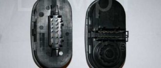
Pinout of the VAZ 2114 window lifter button
A broken window regulator on a car is not only a problem that deprives the driver and passengers of a comfortable ride.
And also an incident that can attract the attention of a traffic inspector for violation of traffic rules. Therefore, knowledge of the design features of a car can help the car owner in a variety of situations. This article provides information on how to pin out the power window button on a VAZ-2114, what may cause the mechanism to break down, and the basics for troubleshooting problems in this device.
Malfunctions and repairs
Instruments or indicators may fail. This could be part of the indicators or even the entire speedometer. VAZ 2110 owners rarely encounter this situation, since the dashboard works properly, especially in domestic cars. Before changing the instrument panel or repairing individual parts, you should make sure that the sensors are working properly - we use the on-board computer.
Inaccurate installation leads to failure of elements. On the instrument panel board, the parts are attached using simple rivets, hence the negative result. The body is constantly subject to vibrations, so the installation simply “falls apart” and breaks appear in the circuit. Repair in this case involves soldering the rivets and thoroughly cleaning the contacts.
After soldering is completed, the instrument panel can be returned to its place. If you have free time, you can go through the contacts using sandpaper. On older cars they usually oxidize, which can prevent the devices from functioning properly.
You can see how to remove the dashboard in the video below.
Probably, hardly anyone will argue with the fact that the VAZ “ten” is not the pinnacle of design thought. However, there is nothing surprising here, because this car was designed back in the last century. At the same time, the compensator, and quite a serious one, in this case is the price. In other words, a certain compromise is proposed - the imperfection of the car in exchange for an acceptable cost. Well, the choice is ultimately made by the car owner himself, deciding whether this option is suitable for him.
You can talk about the advantages and disadvantages of this model for quite a long time. However, this is not what we are talking about now. Those who decide that the “ten” is a suitable option in terms of the ratio between price and quality often want to somewhat refine their iron horse during operation, making changes to both the exterior and the interior.
If we talk about tuning the car interior, then one of the main objects of improvement here is the dashboard. Many people simply don’t like the native version, which, frankly, doesn’t look very attractive. Yes, after the “Zhiguli” this is an undoubted step forward, but it’s already the 21st century outside the window, and I want something more beautiful and pleasing to the eye.
What causes mechanism failure?
The reasons why problems arise in the operation of the window regulator can be divided into two large groups:
- Mechanical.
- Electrical.
The most common ones are listed below:
- Changing the position of the glass or its distortion.
- Failure of guides.
- Drive wear.
- Violation of the integrity of the cables.
- Closing the circuit.
- Oxidation of contacts.
- Failure of functional elements, including the ESP button, the adjustment of which will require theoretical knowledge of pinouts.
You can entrust repairs or replacement of components to specialists or do it yourself.
Installation of an electric window regulator (ESP) on a VAZ-2114
The most popular window lift systems on the VAZ-2114 are rack and pinion types. Their connection is carried out according to the scheme described below.
- Disconnect the on-board power supply from the supply. To do this, remove the terminals from the battery, you can close one - the negative one.
- All the wires that come with the ESP on the VAZ-2114 are twisted together into a bundle.
- The mounting block is removed by unscrewing the screw that controls the position of the latch.
- A wiring harness is mounted into the block in place of the connector of the block.
- The door trim is removed.
- The ESP is installed, along with all the buttons and keys.
By the way, you can make a choice if you wish. Install the buttons and keys that control the window regulator either on the door panel or on the control unit. In the latter case, you will need an additional wire and knowledge of the theory of pinout of the ESP button.
Why you should know the pinout
But before you start this kind of upgrade, you need to understand which wire leads where. The pinout of the instrument panel of a VAZ-2110 car is a very important point when “tuning”. Without this, you risk simply getting confused in a fairly large number of wires, buttons and various sensors. The pinout will be useful in any case - both when making minor improvements and when completely replacing the instrument panel.
The process of installation and dismantling itself is quite labor-intensive, but if you know the correct sequence of actions, then there is nothing particularly difficult about it.
For these works you will need a minimum set of tools - a screwdriver and pliers.
For those who are doing this for the first time, it is best to stock up on self-adhesive pieces of paper, like those on which prices are written in stores, and a pen. With their help, at the time of disassembly, you will indicate, firstly, the sequence of dismantling the parts, and secondly, which wire is connected where. At first glance, this may seem time-consuming, but in fact, for beginners, such markings will help them put the panel back together faster.
At the same time, before starting work, it is best to stock up on a pinout diagram - at least conditional. After all, during the work process you need not to confuse anything and correctly understand each wire and connection during the reassembly process. It is worth noting one very important point. By and large, understanding the pinout of the panel of the “tenth” family will not be difficult even for a beginner.
But you need to remember that there are certain differences here, depending on the plant where the car was manufactured and the year of its manufacture. For example, the instrument panel may be an old model, with a mechanical odometer. If the odometer is electronic, then this is a newer version. Accordingly, there are certain differences in pinout between these panels.
Cleaning the contacts of the window lifter button on a VAZ-2114
If suddenly the power window button on a VAZ-2114 begins to jam or refuses to work at all, you need to take a number of measures to diagnose it and correct the problems.
- First, dismantle the button. To do this, use the tip of a knife or the tip of a flat screwdriver to pick out the edge of the part body. And then they remove it from the nest with their hands. Carefully remove the button along with the fastening chip and wires. If this is not done, then to find the nest you will have to remove the podium.
- The chip remains in the hole in the housing, and the button itself with clamps and contacts needs to be diagnosed and, if necessary, repaired.
- To do this, place the part on a clean, light, flat surface in a well-lit room.
- Use the tip of a flat-head screwdriver to open the button. On both sides, both parts of the device are connected with special “bee” latches. Alternately unlocking one by one, the button is divided into two parts.
- The top part is the contacts. She is dismissed.
- The lower part is the “brains”, among which there is an electronic board. Its dismantling is carried out only after marks are made on the body about its exact location.
The contacts are carefully bent at an angle of up to 90 degrees, after which they are cleaned. And then they move on to analyzing the correct order of connecting the contacts. To do this, it is important to understand the principle of pinout of the power window button.
Tuning options
The instrument panel of the 2114 looks rather dim, so the first option for tuning it may be to install a backlight. This is done quite simply:
- We replace dim lamps with small LED lamps. If you want the light from them to fall evenly, install heat shrink on the lighting elements.
- The wires for the new lamps are connected to the power supply of the stove. You should not use a lot of bright colors, but red and its shades are best for arrows. An excellent analogue would be the blue color of LEDs.
- The second illumination option can be a luminescent tape, which can be used to paste over the instrument panel of the 2114 VAZ. This will slightly update and improve the overall appearance of the interior. You can also replace the interior lamps with diode analogues.
In order for the instrument panel on the VAZ to have a clearer visual perception, the buttons should also be backlit.
Pinout of the VAZ-2114 window lifter button
If you look at both halves, into which the VAZ-2114 window lift button was disassembled, then two rows of contacts and sockets for them clearly appear. One has four elements, the other three. This missing contact is considered the starting point for the subsequent pinout of the VAZ-2114 window lifter button.
With half of the body facing towards you, the contacts are numbered. Each “tooth” corresponds to a wire of a different color.
- Yellow. It connects to the dimensions and serves as a “plus”.
- Black. You can connect it to the negative side of the battery or connect it to ground.
- Red. This is a nutritional plus. Can be connected to a battery. Then the VAZ-2114 window lifter will work both with the ignition on and not. If the driver wants to get a working mechanism only when the engine is started, it should be connected to a similar plus of another unit.
- Green. Output to window lift motor.
- Blue. Output to window lift motor. If the 4th and 5th nodes are swapped, the device will work. But instead of an up arrow, the glass will go down. And vice versa.
- The sixth and seventh ones are automatically connected by “mice” to black, that is, to ground. But some recommendations suggest that this action is not advisable. It is better to connect to the battery.
The fundamental difference between whether the contact is connected to a battery or to another source is that in the first option the mechanism will work even when the ignition is turned off. And the pinout in these cases is relative.
Indicators
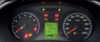
The VAZ 2114 injector dashboard indicators play an important role in informing the user about malfunctions. They help prevent errors in the system, so it is important to know which indicator means what. How does the panel work? If any problem occurs, the sensor immediately sends information to the panel, and the driver will see an orange signal light up.
- The first icon is an oil lamp, which indicates a drop in the oil level in the crankcase of the engine assembly. If there is not enough oil, this indicator will light up. An icon that looks like a fountain indicates that there is insufficient coolant. If it lights up, there is less than 1 liter in the tank.
- Dome with a key - if it lights up, it means there is not enough coolant in the expansion tank.
- The icon looks more like a belt buckle and indicates that the car doors are not completely closed.
- A light bulb crossed out with a cross indicates that the parking lights or brake lights are faulty. Most likely, one of the devices will need to be repaired.
- A circle with six dotted symbols is a graphical indication of a malfunction in the brake system. Most likely, the pads are worn out and need to be checked and replaced.
- An icon with a man and seat belts is an indicator indicating that the driver has not fastened his seat belt.
The earlier version of the 2114 instrument panel had some other symbols, such as emergency oil pressure, handbrake engaged, Chek Engine light, and several others that indicate minor operating errors, but which are no longer used.
Ignition switch pinout for VAZ 2114
I was planning to install auto start and was faced with the fact that in the smart book the ignition switch circuit is not clear =( . I decided to share the circuit and pinout
Connection diagram of the ignition switch VAZ 2113 2114 2115
The vehicle is equipped with an ignition switch (lock) type 2110-3704005 or KZ-881.
The ignition switch is equipped with an anti-theft locking device, a lock to restart the starter when the engine is running, and an illuminated lock socket.
The locking rod of the anti-theft device extends when the key is removed from the lock (the key can only be removed in position “0”). When the key is turned from position “0” to position “I”, the locking rod is retracted inside the lock, contacts “30” and “15” of the ignition switch are closed.
When the key is turned to position “II”, voltage is also supplied to the starter relay. From this position, the key automatically returns to position “I” under the action of a spring. You can turn the key back to position “II” only after first turning it to position “0”.
The circuits that are closed at various key positions are shown in the table below. The ignition switch (lock) connection diagram is shown in the top figure.
Car modifications 2114
VAZ-21140. Modification with an 8-valve injection engine VAZ-2111, 1.5 liters and 77 horsepower. Serial production from 2003 to 2007
VAZ-21144. Modification with an 8-valve VAZ-21114 engine, 1.6 liters and 81.6 horsepower. Years of serial production: 2007-2013.
VAZ-211440. Another modification released in 2007, it was equipped with a VAZ-11183 engine with a volume of 1.6 liters and a power of 82 horsepower. The car was discontinued in 2013.
VAZ-211440-24. Released in 2009, a modification with an injection 16-valve VAZ-21124 engine with a volume of 1.6 liters and a power of 89.1 horsepower. Discontinued in 2013.
VAZ-211440-26. Modification with a 16-valve injection engine VAZ-21126, which complies with the Euro-3 environmental standard, with a volume of 1.6 liters and a power of 98 hp. The car was produced from 2010 to 2013.
Wiring diagram for the ignition switch on VAZ-2113, 2114 and 2115
Wiring diagram for the ignition switch on VAZ-2113, 2114 and 2115
Pinout of the ignition switch VAZ-2113, 2114, 2115:
- comes +12V for the microphone of the sensor of the inserted key;
- the mass comes when the driver's door is open;
- +12V goes to the starter (pin 50);
- +12V goes out after turning on the ignition (pin 15);
- +12V goes out when the key is inserted to pin 5 of the BSK;
- comes +12V to illuminate the lock cylinder;
- +12V comes from the battery (pin 30);
- not used.
| Photo 1, pinout of the ignition switch of a VAZ 2114 | Photo 2, pinout of the ignition switch of the VAZ 2114 |
Sources
- natapku.ru/ustrojstvo/panel-priborov-vaz-2114.html
- autoschemes.rf/shemy/vaz/2113-14-15/151-shema-elektrooborudovaniya-avtomobilya-vaz-2115.html
- 2shemi.ru/raspinovka-pribornoj-paneli-vaz/
- galantmotors.ru/document/shema/2114/2114_scheme_panel.php
- drive2.ru/l/186644/
- galantmotors.ru/document/shema/2114/2114_zamok_zajiganiya.php
- drive2.ru/l/544700810253041946/
Devices 2110, 2115
People call them “Vedeo” because of the VDO inscription. But this is one of the device manufacturers. There is also AutoPribor and SchetMash. Well, you can also find export ones like SAGEM. The first tidy to appear was 45.3802 (2110-3801010)
2110
It is electromechanical. That is, there are magnetic indicators and a motor is installed in the speedometer, which increases the mileage and moves the needle. The speedometer operates from a 6-pulse speed sensor. Pressing a button resets the daily lower counter. Charge lamps also come in large and small ones.
These devices were used on the first VAZ-2115 with a Europanel, and on the VAZ-2120. The IZH-2126 was equipped with a 51.3801 instrument panel, which differed in the design of the scales. Instrument diagram, instruments are illuminated with three lights on top
On 2110 and 2115, an on-board control system unit is used with instruments
2115
2110
It consists of several alarms, the ignition of which is accompanied by blinking and beeping to attract attention. If the driver's door is open and the key is in the ignition, the unit beeps about the “forgotten key”. Block 2110 shows which door is open and differs in size.
Unit indicators: worn front brake pads, burnt-out brake lights or side lights, unfastened driver's seat belt, open doors, low levels of engine oil, coolant and washer fluid.
When the ignition is turned on, the unit lights up all the indicators to visually check their functionality and receive a signal from the liquid level sensors. After checking, the unit does not respond to sensors to prevent false alarms while moving. There are anomalies that continue to respond to all sensors.
Block 2115 contacts
Pinout: 1 — oil level sensor, 2 — coolant level sensor, 3 — washer fluid level sensor, 4 — driver’s seat belt sensor, 5 — brake pad wear sensors, 6 — driver’s door limit switch, 7 — passenger door limit switch (on 2108 and 2113 right door), 8 — interior light, 9 — sensor in the ignition switch, 10 — lamp serviceability relay, 11 — ground, 12 — connected to ground on right-hand drive cars, 13 — ignition.
Block 2110 has two more legs for the door end switches
Not all sensors are installed. Sometimes the unit simply notifies you about a forgotten key and an open door. The expansion tank 2110 uses sensor 2110-3839310 (the shortest), the 21083 uses 21083-3839310 (medium length), and the washer reservoir of both models uses sensor 21083-3839410 (the longest).
The blocks can be old (large, with a huge transistor heatsink, large LEDs...) and new, more compact. They differ in the tone of the tweeter and slightly in design. The unit works if power is supplied to pins 6 (limit switch in the lock) and 13 (ignition).
Information about the warning lamp unit 2110-3803010-10 is classified.
On the VAZ-2115 since 2011, there is no limit switch in the ignition switch (Kalinovsky lock with a coil) and contact 6 of the block is connected to 13, that is, the block plays the role of an indicator (the immobilizer beeps about a forgotten key). On the 2110 with a Europanel, the unit is missing. With the advent of the VAZ-2123, the devices became electric
Instead of a mechanical counter, a display is installed; the hands are moved by stepper motors. Contact 4 of the white block is supplied with constant power to save time and trip odometer readings. If there is no power here, the devices will not work. Under the tachometer there is also a display that displays the time, outside temperature and on some (2115(23)-3801010-04(05)) voltage.
21150-3801010-04
In this picture we see anomaly 2115-3801010-04 with pictures of seat belts and burnt out lamps. Perhaps AvtoVAZ at Samara-2 was going to completely remove the BSK unit and leave only these two light bulbs in the instruments? Holding the button in the devices resets the daily mileage. Pressing - switches the display readings under the tachometer. Turn the button to set the time. Chevrolet Nivas also have an additional display unit 2123-3803010.
On the updated ShNivs, a 2123-3801010-10 tidy is installed, with immobilizer lamps (pin 2 of the white connector) and differential lock (pin 9 of the red), which were moved from the block; instead of the block, a plug 2123-3803010-30 can be installed.
Indicators in the unit: differential lock, immobilizer, power steering, ABS, airbags, EBD and seat belts.
On the VAZ-21214 M there are seat belt and ABS lamps in devices 2115-3801010-20
photo stolen from slavaivannikov
the rear fog lamps were placed in a button, and the glass heating and differential lock lamps were moved to the panel (they were on the old tidy)
And here is a photo of an export Lada 4x4 2022, the speedometer has a scale in miles
Export 21214 2017
Pin 1 of the red block is connected to the outside air temperature sensor 2115-3828210 (placed behind the front bumper, people like to steal it), on the old 2110 unit it was a fuel reserve lamp, now it is lit by the comparator when the sensor resistance is low (the tank is almost empty). The 2110 devices do not have a display under the tachometer. On the 2110, you can install both a new device with a display and an old electromechanical one. Everything will work.
For the latest 2110 model years, the devices may have an airbag lamp instead of a choke lamp. By the way, the choke lamp was used only on carburetor VAZ-2120
Devices 2110
photo stolen from kosdok
Pinout picture
The IZH-2126 also came with a tidy system with two displays 346.3801
It differs from 2115 in the design of the scales, arrows and checking the arrows (they do one pass when the ignition is turned on). Instruments The auto instrument is more expensive, has LED main indicators and the tachometer is marked up to 7000 revolutions compared to VDO instruments.
There are also instruments for VAZ-21106 (with an Opel engine) 21106-3801010 with speedometer markings up to 240 km/h and a display under the tachometer (shows air temperature and time like instruments 2115)
Well, devices 344.3801 are installed on VAZ-1111 Oka cars with a new instrument panel. They differ in the firmware of the tachometer (shows twice the speed, since the engine is two-cylinder).
Diagnostics of the instrument cluster using the example of a Chevrolet Niva:
1. Turn on the ignition. Press the trip odometer reset button and, after turning on the ignition, release it. After this, the instrument cluster enters the “test” mode: — the arrows of all instruments move three times over the entire scale range; — all segments of the liquid crystal display (LCD) are highlighted. 2. After this, you need to clear the processor memory of the electronic instrument cluster by pressing the odometer reset button for at least 5 seconds. 3. Retest. After this, briefly press and release the odometer reset button. The processor software version number (Uer 0.8, Uer 1.1 or other) will appear on the LCD. 4. When you press the reset button again, one of the following codes will appear: 0 – no faults; 1 – microprocessor is faulty; 2 – open circuit of the fuel level indicator sensor; 4 – increased voltage of the on-board network (more than 16+1.8 V); 8 – reduced voltage of the on-board network (less than 8-0.6 V). If there are several faults, the corresponding sum of codes is displayed, for example: 6 (2+4), 10 (2+8), 12 (4+8), 14 (2+4+8).
Data for checking the speedometer
signal - intermittent minus 1 revolution of the speed sensor - 1 meter of distance traveled - 6 pulses.
For example, with an input signal frequency of 133 Hz (connection-break with a minus), the speedometer should show 81-85 km/h. Data for checking the tachometer
signal - intermittent plus With an input signal frequency of 100 Hz (connection-break with plus), the tachometer should show 3000 rpm.
Data for checking the fuel level indicator
signal - If the sensor resistance is 330 Ohms, the arrow should indicate an empty tank.
At 7 Ohms - full. Data for checking the coolant temperature gauge
signal - resistance with a minus If the sensor resistance is 750 Ohms, the needle should show a temperature of 50 degrees. At 86 Ohms - 115 degrees.
That's all. Comrade violet
thanks for the additions. Who stole the photos from - sorry!
VAZ-2115 dashboard diagram
The controls of the VAZ-2115 passenger car are located in accordance with the UNECE norms and regulations. For greater ease of use of handles, buttons, switches and control devices located on the dashboard, they have graphic symbols indicating their functional purpose.
Rice. 1.1 Instrument panel of the VAZ-2115 (diagram).
The dashboard diagram (Fig. 1.1) includes controls:
1 – lever-switch for headlight or turn signal modes.
2 – nozzle for blowing the front door glass.
3 – instrument cluster.
4 – steering wheel.
5 – button to turn off sound signals.
6 – button to turn off the alarm. Pressing the button causes the warning light and direction indicators to flash.
Photo 1. Hazard switch off button
7 – ignition switch combined with an anti-theft device. Never turn off the ignition or remove the key from the lock while driving, otherwise the steering will be blocked and the vehicle will lose control. The ignition key can have three positions:
- 0 – “disabled”. Consumers are disconnected, the key can be easily removed. When the key is removed, the closing mechanism of the anti-theft system is activated. To guarantee the steering shaft block, turn the steering wheel left or right until it clicks. To turn off the anti-theft device, you need to insert the key into the ignition and, turning the steering wheel left and right, turn the key to position “I”;
- I – “ignition”. The ignition is on, the key is not removed, the steering is unlocked;
- II – “starter”. The key cannot be removed, the steering is unlocked. The position is achieved by turning the key to overcome the elastic force of the spring. The key is not locked in this position; it must be held by hand for the starter to operate. The ignition switch is also equipped with a starter activation unit while the engine is running.
To repeat turning on the starter after a failed start attempt, you need to move the ignition key from position “I” to position “0”, and then again to position “II”.
8 – switch lever for windshield washer and windshield wipers.
9 – immobilizer sensor, transmits a special code from the code key through the immobilizer to the engine control unit.
10 – set of signal lights for the on-board control system. The complex contains (Fig. 1.2): 1 – oil level drop signal; 2 – low level signal in the windshield washer tank; 3 – low coolant level signal; 4 – door open signal; 5 – signal of malfunction of the brake light and side lights; 6 – signal of wear of the linings on the brake pads; 7 – the signal indicates that the seat belts are not fastened.
11 – external lighting switch.
12 – block of keys for turning off fog lights, fog lights, heated rear window.
13 – trip computer, installed on some vehicles, designed to display one of the parameters: current fuel consumption (or average total fuel consumption), average speed, distance traveled, current time, time on the road.
14 – plug.
15 – control lamp for anti-lock braking system (ABS). Installed in place of the plug, if equipped with an anti-lock braking system.
16 – airbag control lamp. If the pillow itself is present, it is installed in place of the plug.
17 – central nozzles of the ventilation and heating systems of the cabin.
18 – cover of the glove box (upper). To use the upper glove compartment while the lower glove compartment lid is open, press the upper lid lock lever. The lock lever is located in the niche of the lower glove compartment on top.
19 – side nozzle of the ventilation and heating systems of the cabin.
20 – glove box cover (lower). To open it, you need to press the lock handle to the handle. If the external lighting is turned on, a special illumination of the inside of the box will automatically work.
21 – magazine shelf.
22 – control panel for interior ventilation and heating systems.
23 – socket for audio equipment. It is planned to install audio equipment that meets international standards in size and mounting principle.
24 – ashtray.
Watch a video of testing the dashboard of a VAZ-2115 passenger car here:
How to remove the dashboard of a VAZ-2115
If you decide to remove the instrument panel and carry out independent tuning or DIY repairs, you will need:
1. – Disconnect the ground wire from the battery.
2. – Remove the fastening screws to remove the steering shaft casing.
3. – After disconnecting the wires, remove the ignition switch.
4. – Remove the handles from the heater control levers
5. – Remove the headlight hydraulic adjustment handle.
Rice. 2.1 Instrument panel and its elements: 1 – instrument panel; 2 – dashboard trim; 3 – bracket; 4 – plug; 5 – ashtray; 6 – right cross member; 7 – right console screen; 8 – instrument panel; 9 – central bracket; 10 – left console screen; 11 – left cross member.
6. Remove the screws and disconnect the right 7 and left 10 screens from the instrument panel panel 8 (see Fig. 2.1).
7. Unscrew the screws securing the instrument cluster.
8. Unscrew the screws connecting the right cross member 6 to the dashboard panel 8.
9. Remove plug 4 and unscrew the screw securing the instrument panel panel 8.
10. Remove the instrument panel 8 as an assembly with switches for instrument lighting, fog lights, rear window heating, hazard warning lights and the cigarette lighter.
11. Disconnect all electrical wires.
12. To remove panel 1 assembled with trim 2, remove the screws securing the instrument panel to bracket 3 and left cross member 11.
13. If necessary, you can remove the screws and remove the dashboard trim, as well as the interior ventilation nozzles and air ducts.
Installation of the dashboard is carried out in the reverse order.