Every car owner is concerned about the safety and security of their car. This is especially true for those who are forced to leave their “iron horse” for a long time in public places, as well as in the courtyards of residential buildings. The desire to protect your property is understandable, given the fairly high crime rate. Modern cars are produced with a security system straight from the assembly line. Most often we are talking about the central locking.
It is very convenient and practical, so it remains unrivaled when choosing a security system for little money. Using this device, you can close and open all doors, including the trunk lid, automatically. All this is done both directly by turning the key in the lock, and from the remote control.
Features of standard central locking
AvtoVAZ even installs a central locking system with a remote control from the factory even on the most budget versions of Kalina. However, such a system is clearly not enough to effectively protect a car from theft. The Lada Kalina central locking system is also controlled from the interior. On the driver's door next to the power window control unit there is a central locking button. The ignition key simultaneously functions as a remote control. On its plastic part there are three buttons, the purpose of which is as follows:
- Unlocking. One press – the actuator should click and the driver’s door will open, two presses – the rest.
- Closing. To close all doors at the same time, just press the button once.
- Opening the trunk. Not available on all trim levels, as a trunk lock actuator is required. You can also install the electric drive yourself.
Kalina also provides another important function - rear door locking, as it is also called - child protection. To activate it, you need to use the key to turn the red chip to the right near the lock from the outside. After this, opening the rear doors from the passenger compartment is not possible, so that children cannot accidentally fall out while driving.
The central locking system does not have anti-theft functions; there are no shock sensors. All that the central lock can do is signal an unauthorized opening.
Wiring
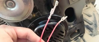
As practice shows, due to the lack of contact, you can often observe a situation where the central lock does not close the doors using the key fob. The system seems to be working, but when I press the button nothing happens.
It's all because of the wiring. It is necessary to carefully check all connections that are related to the alarm system, as well as to the central locking. Even if the contact moves away just a little, this can already cause malfunctions. Do not forget that one of the connections is inside the door - you will have to remove the trim. You should first check the condition of the wire that goes to the motor - it can “stick” to ground.
There are a lot of questions and discussions related to the operation of the central lock on numerous forums. Sometimes the central locking only closes the driver's door - this is a typical malfunction, the cause of which lies in the wiring and contacts. The fact is that a special activator is installed in the driver's door. It has not two, but five contacts. The activator controls the operation of all locks in the remaining doors. The microswitch inside the activator may also fail.
If the wiring is connected incorrectly, then this is the answer to the question about the poor operation of the central locking. It is enough to open one control contact, and the system will not work as it should.
Basic central locking malfunctions and methods for eliminating them
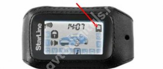
There are times when, after pressing the door unlock button, you may encounter a lack of response to the command. The lock cannot be removed and the central lock does not respond to button presses on the remote control. Conclusion - Kalina's central locking does not work.
You can gain access to the interior using a key, but in this case the sound alarm is not deactivated, and everyone will know when the car is opened. If the system does not respond to commands from the remote control, there may not be many problems: either the batteries in the remote control are low and need to be replaced, or synchronization is lost. In this case, it is not repair that is required, but restoration of the system's functionality.
Auto-assistance
On Lada Kalina passenger cars, on all its trim levels, a central locking system is installed, which has a remote control from a remote control located on the ignition key, with the ability to open and close all doors using the key, through the driver's door lock. In other words, central locking has essentially become standard equipment on these cars. But on some trim levels, the central locking system also includes a trunk lock, which is opened and closed using a separate button on the remote control.
Problems with the operation of the central locking on some Lada Kalina cars arise when using the remote control, which closes only one driver's door, while the passenger doors remain open. To find this malfunction, you will need a tester to check whether an impulse is supplied from pin No. 15 of the electrical package to the red-blue wire (this wire color is shown for the “Norma” electrical package unit), through which voltage is supplied to the passenger door lock activators. If there is no pulse at this connector, the fault is in the electrical package, and if there is a pulse, then you will have to check the condition of all other connectors and the integrity of the wiring harness going to the passenger door actuators.
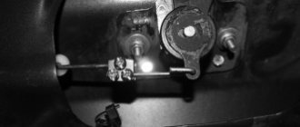
Sometimes, a malfunction of the central locking associated with the operation of only one lock on the driver's door manifests itself audibly. The driver of a Lada Kalina, when closing or opening the doors, hears a crashing sound coming from the area of the center console where the central locking control module is located. This module contains two relays, through which voltage is supplied to the activators when the locks are opened and closed. And the sound that the driver hears is precisely what these relays emit due to the fact that the contact in the fuse through which voltage is supplied to them has become unreliable. This fuse is located inside a black tube on a pink wire, which can be found in the wiring harness behind the fuse mounting block on the center panel.
If only one door lock fails, a possible malfunction may be the deformation of the pin, since it is on it that the plastic button is located, which, when pressed, closes the lock of that door. You can check this version by unscrewing this button and removing it from the rod, followed by an attempt to close the Kalina door locks using the remote control. If all the door locks close, then this deformation of the rod will have to be corrected.
Restoring synchronization
Synchronization may be lost if there is a short-term (from 6 seconds) lack of power to the microcircuit in the key fob. In this case, desynchronization may actually occur, i.e. the connection between the remote control and the control unit of the central locking Lada Kalina is lost. According to the operating manual, if such situations arise, it is necessary to register the key fob again, entering data about it into the memory of the central locking system. You should immediately take into account that the procedure is far from the simplest and most understandable, and you also need a special training key. You can try to restore synchronization as follows:
- Turn the ignition switch with the key that requires synchronization.
- Wait 6 seconds.
- After the immobilizer lamp stops flashing, the ignition can be turned off.
After 10 seconds, the same key is used to start the car again. If the immobilizer warning light does not blink, it means that synchronization has been restored.
At first glance, nothing complicated, but this method does not help in all cases. If there is a training key, but there is no previously registered key, then the ignition is first turned on, then turned off. After the immobilizer warning lamp stops flashing, within six seconds the key is moved to the second position of the ignition switch (starter).
Working with the glass unit control unit
Window control unit Kalina Sport
After reading the manual, you should start by connecting the hood and trunk wire ends. The color of these wires is the same black and white. How can you tell them apart? The wire transmitting the signal to the trunk is always located on the right, the hood wire is located to the left. We connect to the luggage wire. To avoid making mistakes during installation, remember that the trunk wire is the outermost. Then you need to connect the limit switches from the door wires in such a way that the doors then close. To do this you will need 3 1 Ohm diode bulbs.
There is 1 limit switch coming from the doors, while in the BUS there are 3 such door limit switches: 2 for the front doors and 1 for both rear doors. Therefore, the alarm wire must be separated into 3 parts and soldered to each one with one short one. Then solder 1 diode there, and then connect it to the brown-red wire of the front door on the right, to the white-blue wire of the front left, and the white-red wire to the rear. The wiring diagram should be included in the manual.
At the next stage, we connect the LED to the left post, having previously made a hole. For reliability, we secure the part with something on the other side. The antenna must be attached approximately in the same place as the rear view mirror, at a distance of about 5 mm. The shock sensor can be installed on the metal under the mat. If we talk about installing it on plastic, this is not a very good idea, since it can lead to false alarms.
Conversion into a single door unlocking impulse
The controller of the central locking control unit opens the doors in two stages: one press of the button unlocks the driver’s door, two presses – all others. But you can make it so that everything unlocks after one press. This is very easy to do:
- Turn on the ignition.
- Press the unlock and close buttons at the same time and hold for at least five seconds.
- After the beep, the key can be released.
When the buzzer sounds once, the system notifies you of the transition to a new mode. Returning everything to the way it was before is just as easy. To do this, repeat the above procedure and wait for the double buzzer to confirm the transition to the default settings.
Recommendations for both cases
First of all, we note that when connecting the relay to the power wiring, you cannot make the control pulse too long. Setting the value for more than a second can burn out the actuators. Here we were talking about programming, and now let's talk about the electrical part. As you know, before installation you need to open the hood and disconnect the negative terminal.
Negative terminal, battery
This advice should not be ignored in any case.
As for installation, it will be better if the power wire taps are carried out by an auto electrician. With signal wiring, everything is simpler, but the rules will be the same in each case:
- Do not let the cord touch the insulation to metal parts. If contact occurs, additional protection is used. For example, a heat-resistant tube placed over electrical tape is suitable;
- It is better to connect any power cables using twisting. Each twisting point is carefully isolated.
- The cross-section of wires carrying significant current must be sufficient so that the conductor does not heat up. This is how you can protect yourself from unforeseen consequences.
The last tip concerns power wiring. And the ability to twist is a whole art.
Twisting two stranded wires
You cannot learn this art in one day.
When connecting any equipment, you should strive to make as few changes as possible to the standard wiring.
There must be an opportunity to do the following: return everything as it was. Sometimes it happens that one or more signaling parameters do not take a value that is suitable for the car. And then, the alarm system is changed or they refuse to use it altogether. This needs to be taken into account.
Replacing the battery in the key fob
A sign of a low key fob battery will be the LED flashing quickly when you press any button. The central locking does not respond to commands. It is worth noting that a discharged battery will not affect the ability to start the engine. Since the immobilizer can easily read the code written on the chip, synchronization will not be lost.
Disassembling the key fob is very simple; just unscrew one screw on the body and, using any available tool, remove the cover on which the buttons are located. Next, the printed circuit board is removed, under which the battery is located. You need to determine its type by reading the letter and number combination. When replacing, be sure to take into account those same 6 seconds, i.e. have time to install a new battery during this time, otherwise it will be necessary to restore synchronization.
People's Councils
If you are confident that the key fob is working, but the central locking does not work or does not work correctly, then you can try the following:
- Replace the central locking fuse Kalina F22, which protects the controller's power circuit (located in the mounting block).
- The power supply circuit to the actuator of one of the doors may be broken. In this case, you need to open it 90° and find a broken contact or connector.
- It happens that the reason is that the key fob screw is too tight. You need to weaken it, and the functions will be restored.
In each specific case, atypical malfunctions may occur, so the above list is not exhaustive.
Circuit breakers
In this case, the lock will not only not close, but will also stop opening the doors. It's worth taking a look at what's going on in the fuse box. The fact is that the central locking system itself is quite dynamic. Various short circuits in its wiring are by no means uncommon.
If this is a standard lock, then you should look for its fuse in the factory block. If an alarm system is installed (and often it is this that controls the operation of the central locking), then you should look for the fuse on the positive power wire of the unit.
The malfunction of at least one of these objects explains the problem with the central locking. The way out of the situation is simple. You need to replace the blown fuse with a new one. Sometimes you have to struggle with removal - the element sits tightly in the connector.
Installation and connection of central locking depending on the modification of Kalina
The central locking is controlled by an electronic unit, from which wires go to the door actuators. A wire also goes from the block to the driver's door microphone, which is located inside the actuator. When connecting, installing or repairing the central locking system after dismantling the left door trim, you need to find the cable from the drive to the 7-pin connector.
Central lock connection
Depending on the configuration (“Norma”, “Standard”, “Lux”) under the casing you can see:
- Six wires suitable for the connector (drive and two microphones).
- Unconnected wires from the drive.
- Lack of wires that should be in the connector on pins 4/6.
If there is an alarm, then wires 2/7 must be connected to the central locking unit. If the package does not include connecting all the actuators, then you need to do this yourself by connecting the missing ones to the control unit. To do this, you can use a two-wire cable that runs from the door to the central locking control unit. The electrical circuit of one or another modification of Kalina will help with the work.
Central lock connection diagram
Album of schemes for "VAZ 1118"
The Lada Kalina technical manual has such an album. The general scheme includes 59 components, among which you can find:
- sources and consumers;
- protective and control elements;
- ECU;
- sensors
A separate printed block displays the electrical circuit for connecting the electronic motor control module with other system components. We are talking about spark plugs, injectors, sensors, and the ignition unit of the Lada Kalina car.
There is also a separate electrical diagram that highlights the front and rear cable harnesses. A detailed display of all connections of the electrical components of the front panel in the cabin is provided. In addition, the diagram contains clear connections for the wiring harnesses of the door panels and the interior ventilation unit.
In order for the cable connections to ensure reliable contact, they are connected to special blocks with terminals. All terminals are compatible with cable harnesses, the wires of which have their own characteristic sheath color. Each electrical diagram in the album is designed in such a way that the color shade of the sheath of a particular cable actually matches the color shown in the documentation.
Numbers are written next to the drawn lines, allowing you to use the symbols to determine the connector to which a particular wire fits. For example, the marking on the “9/14” diagram “tells” us that this cable is connected to the 9th block via connector No. 14.
No work on modifying the electrical system or connecting additional electrical equipment can be carried out without electrical circuits. Next you will find a set of electrical diagrams for VAZ 1117, 1118 and 1119.
Connecting the central locking system for the “Lux” package
This method is also relevant for Lada Kalina Cross in the “Norma” configuration. “Lux” and configurations with additional options imply the presence of an armrest with installed central locking buttons and electric windows. From the button contacts you need to take the one that receives power after pressing, and stretch the wire to the alarm module. To connect, you can use the following diagram:
Connecting the central locking system for the “Lux” package
This connection option is suitable specifically for the “Lux” configuration, since it has a standard alarm system, and the central locking can be installed independently if for some reason it fails.
When connecting the central locking system, all work must be carried out with the vehicle's electrical equipment de-energized. Wires must be laid so that they do not touch metal. If this is not possible, then a tube is installed to protect the cable from breakage and other negative factors.
Power supplies
In the on-board network of the model we are considering, all pantographs operate at a voltage of 12 V and consume direct current. The electrical circuit for their switching is single-wire.
The wiring diagram contains components that are divided into 4 categories:
- energy sources;
- its consumers;
- protective components;
- sensors
The “representatives” of the first two groups, with their negative terminals, are connected via wires to the body, which appears as “ground”. If we talk about the sources, then there are two of them in the car: the battery and the generator set. When the engine is running, the generator produces power, and when the engine is stopped, the battery is “occupied” with supplying the current collectors with electricity. The generator unit recharges the battery during its operation.
The principle of operation of the generator is quite simple. By means of a belt drive from the rotating crankshaft pulley, the rotor of the generator unit is driven in a circular motion. Thus, alternating current is generated, which is converted into direct current by means of a rectifier module. Over time, the rotor shaft bearings become unusable. They initially contain a lubricant, which gradually loses its properties. The stator of the device has a three-phase winding and is connected to the cover with four studs. There is also a voltage regulator in the generator unit. He monitors that this indicator is within 14.5-15.0 Volts. Note that the rotation ratio of the motor to the generator is 1:2.4. The maximum generated current is 85A.
Let's take a closer look at the rotor. Its field windings are connected by soldering to copper rings, which are located on the element shaft and provide contact. The voltage regulator is a non-separable part and if it breaks, it requires no alternative replacement. To protect the network from voltage surges that occur at the moment of ignition, a special capacitor is connected between the positive valve and the ground terminal.
When the motor is stopped, the battery supplies power to all required pantographs. This device makes it possible to start the motor. The electrical circuit of the Lada Kalina car provides for a parallel electrical connection of the battery and the generator set.
The negative terminal of the battery is connected exclusively to the body “mass” contact, and the positive terminal is connected to the corresponding “B+” terminal present on the generator.
Do not remove the battery while the engine is running. This action will lead to a drop in the mains voltage, which will lead to the failure of expensive pantographs.
Connecting the central locking system in the “Norma” configuration
In inexpensive trim levels, there is no button to close the doors from the interior at all. In this case, the connection is made according to the following scheme:
Connecting the central locking system in the “Norma” configuration
Unlike the connection diagrams for the central locking system in the Kalina “Lux” configuration, there are no resistors and the “+” voltage is not used. But in this case, when you press the close button, all doors will be locked, and when you press the unlock button, only the driver's door will open. The options considered are among the simplest; more complex schemes require special skills, so it is better to entrust their implementation to professionals at a service station.
Prevention
As a measure to prevent breakdowns, experienced specialists recommend periodically performing maintenance on electrical circuits. This requires a complete review of all wires and disconnectors twice a year for damage to the braiding and oxidation of copper contacts. Damaged parts or loose joints must be replaced with new ones.
The pinout of panels of the Kalina car from Lada is distinguished by its simplicity and reliability. There are no complex controllers or blocks here. Consequently, system maintenance and troubleshooting do not require in-depth knowledge of electronics or expensive tools.
Pulse programming
When connecting a central lock, it is not enough to perform all the steps in the correct sequence; you also need to select the required pulse duration for the locks to operate. If it is too large, the actuators will overheat; if it is insufficient, it will not be enough to open and close. In the luxury configuration, all electronics usually “fall asleep” after 15 minutes of inactivity. To awaken it, an additional impulse is needed.
Central locking is a simple device, but it can secure your car from criminals much more effectively than a police cap on the passenger seat. The centralized door lock system is the most convenient way to quickly open and close them. If this security system is supplemented with a good car alarm, this will prevent you from ending up in a situation where your car is stolen or damaged.
We recommend reading:
- Daytime running lights for Kalina
- Representatives of the Lada Kalina model range
- We screw the fog lights on the Lada Kalina
- Advantages and disadvantages of Lada Kalina automatic
- Suspension for Lada Kalina car
- Steering mechanism Lada Kalina
Installation instructions
Installation of the device is carried out as follows:
- First, the plastic door trim is removed and a location for installing the unit is selected. When choosing a location, it is necessary to take into account the location of the window lifter elements. According to many experts, it is better to install the system in the lower left corner of the door.
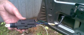
- The next step is to install the lock activators, each of which is mounted separately on each door. It is necessary to drill the corresponding holes in the structure in advance and secure them with self-tapping screws. After this, the activator must be connected to the rod. Next, the activators need to install clamps on the manual control elements of the central locking.
- The wiring is being laid - All wires must be securely fixed; plastic clamps can be used for this. They should not be placed at the bottom of the door, since moisture usually collects in this place, so it is better to choose a place between the door and the body, installing a rubber tube here in advance. Thanks to it, the wiring can be protected from damage.
- The next step will be to dismantle the control panel. Having done this, the old wiring from the window regulators can be removed and a new one can be laid, which is subsequently connected to the drive.
- After this, the activator drives are connected. When all these steps are completed, the wiring must be pushed under the control panel on one side, and into the glove box on the other side. A pass-through pipe is mounted into the rack; a screwdriver may be required to install it.
- Now a fuse is connected to the connector and this circuit is connected to the central locking power supply, the entire structure is installed under the center console. The cable from the central locking system must be connected to the on-board network, plus to the fuse, minus to the body. Assembly is carried out in reverse order.