Central locking is installed on every version of Lada Kalina cars and problems associated with this device sometimes arise even on new cars. Here enough information will be collected to find the cause or repair the central locking and car alarm. Over time, the section will be supplemented with useful information on installing and configuring various types of security systems.
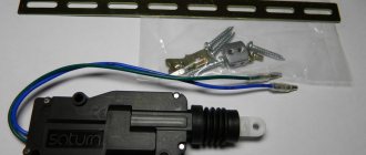
Greetings to all blog readers, and today’s topic will be devoted to such a process as replacing the electric lock in the rear door of a car.
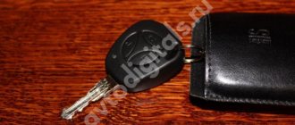
So, I’ll start with the fact that about a year ago the first problems appeared with the standard alarm key fob on my Kalina.
Recently I received a letter in the mail with a proposal to write an article about a certain modification of the Lada Kalina, thanks to which the trunk door can be opened.
This article was sent to me by email by one of the owners of Kalina, and I decided to publish it because I have experience solving a similar problem.
A couple of days ago, I received an email from a blog reader with a question about the remote control unit for the security alarm. I decided to write.
Very often, Kalina owners are interested in the location of the immobilizer unit (standard anti-theft system). And in fact, finding it is quite difficult.
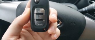
For those whose Kalina is protected under a standard security system, with the usual three-button key fob, this article will be useful.
I would like to share one rather interesting and very controversial topic regarding the possibility of a standard alarm system for the Lada Kalina. Of course, about the hidden ones.
Now even on the cheapest version, central locking with remote control is standard. Although the manufacturer calls it.
© Lada Kalina Blog. All rights reserved. Copying of materials is prohibited without the written consent of the copyright owner.
This site is a private unofficial project and does not pursue any commercial purposes. All materials located on this site are provided for informational purposes only, without any warranties, express or implied. The site owner is not responsible for the application of the site information and its use. All risks when using the site are borne by the user. The resource is intended for readers over 18 years of age.
Every car owner is concerned about the safety and security of their car. This is especially true for those who are forced to leave their “iron horse” for a long time in public places, as well as in the courtyards of residential buildings. The desire to protect your property is understandable, given the fairly high crime rate. Modern cars are produced with a security system straight from the assembly line. Most often we are talking about the central locking.
It is very convenient and practical, so it remains unrivaled when choosing a security system for little money. Using this device, you can close and open all doors, including the trunk lid, automatically. All this is done both directly by turning the key in the lock, and from the remote control.
Lada Kalina - fuse and relay blocks
Lada Kalina 1st
generation was produced in 2004, 2005, 2006, 2007, 2008, 2009, 2010, 2011, 2012 and 2013 under internal serial numbers
VAZ-1117, VAZ-1118, VAZ-1119
with sedan bodies , hatchback, station wagon. In this article we will show a description of fuses and relays of the 1st generation Lada Kalina with block diagrams and photographs. Note the fuse responsible for the cigarette lighter.
The design of the blocks and the purpose of the elements in them may differ from those presented and depend on the year of manufacture and level of equipment of your Lada Kalina. Check the description with yours, printed on the back of the protective cover, or other technical documentation.
Album of schemes for "VAZ 1118"
The Lada Kalina technical manual has such an album. The general scheme includes 59 components, among which you can find:
- sources and consumers;
- protective and control elements;
- ECU;
- sensors
A separate printed block displays the electrical circuit for connecting the electronic motor control module with other system components. We are talking about spark plugs, injectors, sensors, and the ignition unit of the Lada Kalina car.
There is also a separate electrical diagram that highlights the front and rear cable harnesses. A detailed display of all connections of the electrical components of the front panel in the cabin is provided. In addition, the diagram contains clear connections for the wiring harnesses of the door panels and the interior ventilation unit.
In order for the cable connections to ensure reliable contact, they are connected to special blocks with terminals. All terminals are compatible with cable harnesses, the wires of which have their own characteristic sheath color. Each electrical diagram in the album is designed in such a way that the color shade of the sheath of a particular cable actually matches the color shown in the documentation.
Numbers are written next to the drawn lines, allowing you to use the symbols to determine the connector to which a particular wire fits. For example, the marking on the “9/14” diagram “tells” us that this cable is connected to the 9th block via connector No. 14.
No work on modifying the electrical system or connecting additional electrical equipment can be carried out without electrical circuits. Next you will find a set of electrical diagrams for VAZ 1117, 1118 and 1119.
Main block
The main block with fuses and relays is located under the instrument panel on the driver's side, behind the protective cover.
Scheme Option 1
Scheme Option 2
Description of fuses
p, blockquote 10,0,0,0,0 —>
| F1 | 15A Electronic engine control unit, cooling fan relay, fuel injectors |
| F2 | 30A Electric windows |
| F3 | 15A Hazard alarm |
| F4 | 20A Windshield wiper, airbag |
| F5 | 25A Heater (viburnum heater fuse), Electric power steering control unit, Windshield washer |
| F6 | 20A Horn |
| F7 | 10A LCD instrument cluster indicator, Brake light switch and lamps, Interior lighting |
| F8 | 20A Heated rear window |
| F9 | 5A Side light bulbs on the right side, Glove box light bulb |
| F10 | 5A Side light bulbs on the left side, Outside lighting indicator in the instrument cluster, License plate light bulbs |
| F11 | 7.55A Rear fog light, Immobilizer control unit |
| F12 | 7.5A Low beam lamp right block - headlights |
| F13 | 7.5A Low beam lamp left block - headlights |
| F14 | 10A High beam lamp right block - headlights |
| F15 | 10A High beam lamp left block - headlights |
| F16 | 10A Right fog lamp |
| F17 | 10A Left fog lamp |
| F18 | 20A Heated front seats, cigarette lighter |
| F19 | 10A ABS |
| F20 | 15A Cigarette lighter , luggage compartment lock, diagnostic connector |
| F21 | 10A Transmission reverse lock circuit |
| F22 | 15A Security alarm control unit |
| F23 | 10A Electric power steering control unit |
| F24 | 7.5A Air conditioner |
| F25 | 10A Interior lighting, brake lights |
| F26 | 25A ABS |
| F27 | Spare |
| F28 | Spare |
| F29 | Spare |
| F30 | Spare |
| F31 | 50A Electric power steering |
| F32 | 30A ABS |
Fuse number 20 at 15A is responsible for the cigarette lighter.
Relay purpose
p, blockquote 12,1,0,0,0 —>
| K1 | Headlight washer relay |
| K2 | Power window relay |
| K3 | Additional starter relay |
| K4 | Ignition switch unloading relay |
| K5 | Alarm relay |
| K6 | Heated Seat Relay / Wiper Relay |
| K7 | High beam relay |
| K8 | Horn relay |
| K9 | Fog light relay |
| K10 | Relay for heated rear window and exterior mirrors |
| K11 | Seat heating relay |
| K12 | Fuel pump relay |
| K13 | Reverse light relay |
| K14 | Radiator cooling fan relay |
| K15 | Heated windshield relay |
| K16 | Heated windshield relay |
| K17 | A/C compressor clutch relay |
The driver's actuator toggle switch is damaged
Depends on whether the viburnum is standard or luxury. It’s easier with the standard, but with the luxury, they say, it’s a pain in the ass.
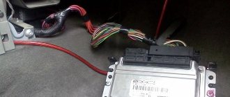
I also had this problem. I have a standard unit under the seat. The implantation of additional signaling was successful. I connected the limit switches directly to the block wires via diode isolation. The turn signals are the same, soldered directly to the wires of the unit.
However, now the problem of implementing central locking has arisen - it is completely unclear how this system works on a standard unit. In general, I would like to get advice from those who have already installed an alarm system on top of the main unit - there is complete chaos going on with the central locking system. Everything is written simply “+12V pulse”, but in reality there is no operating logic at all.