The VAZ 1111 Oka is an example of a Soviet and Russian car that was created with an eye to efficiency and compactness. And the time of its production coincides with the moment when even in the Soviet Union they noticed that traffic jams were starting to appear in large cities, and it was becoming more and more difficult to park a car. The car turned out great, despite all the laughs about its size. Today we are interested in its ignition system, how it works and what features it has.
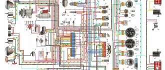
Scheme of the contactless ignition system of the OKA VAZ-1111 - 1113 car
Scheme of the contactless ignition system of the OKA VAZ-1111 - 1113 car : 1 - ignition switch relay; 2 — ignition switch; 3 - fuse block; 4 - switch; 5—sparking moment sensor; 6 — ignition coil; 7 - spark plugs.
Spark timing sensor - type 5520.3706 (until 1989, a type 55.3706 sensor was installed) with built-in vacuum and centrifugal ignition timing regulators. It sets the moment of spark formation depending on its initial setting, the number of revolutions of the crankshaft and the load on the engine. Reading of control pulses is based on the Hall effect. There is one pulse for each revolution of the crankshaft (two for each revolution of the camshaft). The initial ignition timing angle for the VAZ-1111 engine is -1 ±1° BTDC, for the VAZ-11113 - 4±1° BTDC.
The switch - type 3620.3734, or 36.3734, or HIM-52 opens the power circuit of the primary winding of the ignition coil, converting the control pulses of the sensor into current pulses in the ignition coil. The switch is checked with an oscilloscope using a special method; if a malfunction is suspected (interruptions in engine operation, shots in the muffler), replace it with a known good one. Do not disconnect the switch connector while the ignition is on - this may damage it (as well as other components of the ignition system).
The ignition coil is two-terminal, dry, type 29.3705 - with an open magnetic circuit, or type 3012.3705 - with a closed magnetic circuit. Data for testing: resistance of the primary winding at 25°C - (0.5+0.05) Ohm, secondary - (11 ± 1.5) kOhm. The insulation resistance to ground is at least 50 MOhm. Spark plugs - type A17DVR, or A17DVRM, or their imported analogues (with noise suppression resistors with a resistance of 4-10 kOhm). The gap between the electrodes should be within 0.7-0.8 mm (checked with a round wire probe).
High-voltage wires - type PVVP-8 with distributed resistance (2000±200) Ohm/m or PVPPV-40 with distributed resistance (2550±270) Ohm/m. Do not touch high-voltage wires while the engine is running - this may result in electrical injury. It is also prohibited to start the engine or allow it to operate with an open HIGH VOLTAGE circuit (crushed wires) - this can lead to insulation burnout and failure of the electronic components of the ignition system.
Ignition switch - type 2108-3704005-40 or KZ813 with an anti-theft locking device, blocking against re-starting the starter without first turning off the ignition. When the key is turned to the “ignition” position, voltage is applied to the control input of an additional relay type 113.3747-10, which, in turn, supplies voltage to the ignition coil and switch. Thus, the contacts of the ignition switch are relieved.
Source
Modernization of the ignition system of VAZ – 1111 “Oka”
As you know, Oka cars are equipped with a rather imperfect 2-spark ignition system (similar to the options installed on some motorcycles). In general, the use of such a principle of organizing the ignition system cannot be called particularly flawed, however, due to the design features and the not very high quality of individual elements, it has a number of significant disadvantages. In particular, Oka owners are well aware of the existence of problems with starting these cars in winter (even a slightly “supercharged” battery simply cannot cope with maintaining a “push-pull” spark). The state of insulation between the high-voltage and low-voltage circuits of standard double-spark coils does not stand up to criticism either, as a result of which they very quickly fail due to moisture ingress and in damp weather. And, finally, such an unpleasant phenomenon as occasional “shots” in the muffler is also a consequence of the use of a two-spark ignition system - when an incompletely burned mixture is squeezed out by a piston into the intake manifold and, with the valves open, is ignited there by a “non-working” spark.
Be that as it may, the need to modernize the ignition system of the VAZ-1111 Oka is beyond doubt, and currently three main methods are most widespread:
- Introduction into the system of a standard VAZ 2108 distributor with high-voltage ignition distribution, one ignition coil and one switch (from the same place). In this case, two of the four curtains in the spark moment sensor are cut off, or unnecessary spark plugs are fixed in a neutral place in the engine compartment (it is prohibited to leave excess high-voltage wires without discharge).
- Installation of a combined two-spark unit in an imported or domestic version of the “all-in-one” type (switch + coil);
- Installation of the coils of two oil-filled ignition coils from the VAZ 2108, as well as two switches with the combination of their inputs to the output of the torque sensor.
In general, any of these methods allows you to achieve a certain positive result, although each of them is not without some disadvantages. So the first method reduces the overall reliability of the system due to the use of additional elements, namely a high-voltage distributor and several high-voltage wires. The second method is simply to use a more reliable version of the same two-spark system (if you can find decent equipment). Finally, the third method does not eliminate the problem of an “unnecessary” spark and is associated with energy expenditure on the second ignition coil.
Based on the above, it makes sense to carry out a more original and effective modernization, namely, leave only one curtain in the original spark sensor and add a pair of Hall sensors to the system, spaced 180 degrees apart. In other words, it is proposed to implement the third option, eliminating its shortcomings by providing ignition in each of the cylinders using Hall sensors.
Preparatory work
- We are modifying the DMI unit to make it possible to connect two Hall sensors (by replacing the standard connector with a connector with the required number of contacts);
- we cut one of the DMI curtains under the base (the DMI will have to be disassembled), making sure that there are no shavings and crumbs of metal left that could get into the magnetic gap of the Hall sensors;
- we install high-quality injection spark plugs with a gap of 1.1 mm (BOSCH WR7D+X is suitable);
- we use domestic coils, type 27.3705;
- to compactly place the switch one above the other, we machine brass spacers to ensure a distance between the switches of approximately 27mm;
- “HORS” products with silicone caps are suitable as high-voltage wires. We additionally protect the wires from possible overheating with a heat-shrinkable tube.
Implementation Features
To ensure normal operation of the system, the hall sensors must be of the same type (from the same batch), otherwise the direction of the magnets will be disrupted and, as a result, the DMI curtain will be remagnetized. Simply put, you will have to abandon the original sensor.
Power wiring for plus 12V on the relay (in the standard version, blue-black) is carried out with a wire with a cross-section of at least 4 sq mm, while for switches a stranded wire of 2.5 mm is sufficient. It is better not to use standard wiring as there are significant losses on it.
For the signal part, you can take a shielded multi-core cable with a core cross-section of 0.2 mm (the screen will help get rid of interference).
The main difficulty in manufacturing a modernized ignition system is the need to accurately position the Hall sensors on the installation platform. The main problem is that the sensors must be installed with an accuracy of 0.1 mm opposite each other (relative to the circle passing through the centers of their slots). In any case, the sensor mismatch should not exceed 1 degree of crankshaft rotation. If this condition is not met, a significant drop in engine power is observed. For the same reasons, you should ensure that all elements of the system are securely fastened.
The ignition timing is set according to the standard method.
How to set the ignition on Oka
Hello. I did a major overhaul of the engine on the Oka River (VAZ 11113), tell me how to set the ignition correctly?
I drove fine in the evening. It hasn't started in the morning. Fills the candles.
Doesn't pick up speed, shoots into the carburetor when you start accelerating. It works fine at idle, what's wrong? Thank you.
Is it possible to understand from the spark plugs (the color of the soot) which ignition (later or earlier) is installed? Oka.
Hello, please tell me how to check the spark on the spark plugs.
Why are the spark plugs constantly flooding? Could it be that the ignition has gone wrong?
From scratch, after repair, in order to correctly set the ignition on a VAZ OKA, you need to set it according to the marks, as the book says, and make the adjustment directly by ear. To set the ignition on Oka, do the following:
- Lift the hood and remove the inspection plug for the flywheel ring on the manual transmission.
- Turn the steering wheel all the way to the right and remove the plug in the wheel arch opposite the crankshaft pulley. Next, place a wrench with a nineteen head on the pulley mounting bolt.
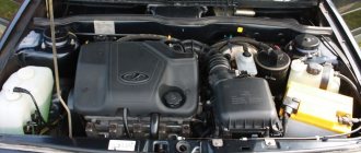
About the engine
For these models, engines 2108 and 21083 were taken as the basis. They are 2-cylinder engines with an in-line vertical arrangement of cylinders. The camshaft is installed in the cylinder head. The working volume is 649 cm 3 and 749 cm 3. The increase in volume is obtained by increasing the diameter of the pistons from 76 mm to 82 mm. The cylinder blocks of these engines, heads, flywheels, and pulleys are different.
Many spare parts are unified with their 4-cylinder variants. The power supply system is carburetor, but with changed calibration data. In 1990, the timing belt on the power unit was replaced. If the previous product had semicircular teeth, then on the new one they began to have a trapezoidal shape with a groove at the top of the tooth. The pulleys were changed to match the tooth profile, but the belts themselves are interchangeable; you can use both new and old parts.
It is possible to obtain maximum efficiency from using an internal combustion engine only with the correct adjustment of the valve timing. There are marks on the timing drive for this purpose. One of them is the protrusion on the rear cover for the drive belt protection, which should coincide with the mark on the camshaft pulley. The second mark is located at the bottom of the cylinder block, and it coincides with the mark on the crankshaft pulley. The piston of the first cylinder should be at top dead center at this time.
Are the valves bending?
This question worries many owners, since after such an “incident” a costly overhaul of the power unit will follow. Mechanics know of cases where, after the pistons met the valves, in addition to bent valves, the piston heads were damaged and the guide bushings in the cylinder head were destroyed. The engine, based on the VAZ 21083 engine, is free from such shortcomings. The pistons of this internal combustion engine have recesses that prevent the valve head from meeting the upward-moving piston.
This problem can occur in two cases:
- Cutting teeth on the timing belt.
- The alignment marks on the engine being repaired are not aligned correctly.
To avoid this, you should carefully study the process of replacing the belt, or seek help from service center specialists.
Ignition adjustment with strobe light
Initially, make sure that the first cylinder is at TDC. Make sure that the marks on the flywheel and on the crankshaft rear oil seal holder match. In this case, one division of the holder scale is equal to 2 degrees of crankshaft rotation. Instead of using a spark as a guide, it is more correct to use a strobe light. Using a strobe, ignition adjustment on the Oka is performed as follows:
- You need to disconnect the hose from the vacuum regulator.
- To check the ignition timing, the positive wire of the strobe light must be connected to the positive terminal of the battery, and the ground wire to the negative terminal of the battery.
- Remove the tip of the high-voltage wire from the spark plug of the first cylinder and connect it to the strobe sensor (follow according to the instructions included with the measuring device).
- There is a hatch on the clutch housing; you need to remove the rubber plug from it.
- If the ignition is set correctly, then the mark on the flywheel (1 in the photo below) will be located between the middle (2 in the photo below) and the previous (3 in the photo below) divisions.
- After this, we start the engine and point the strobe light into the clutch housing hatch so that its flashing stream of light is directed at the marks.
- The ignition timing on the Oka engine is adjusted by turning the spark sensor housing.
Source
Checking and adjusting ignition timing
Ignition timing is a very important parameter on which the normal operation of the engine depends. If this timing (ignition timing) is set incorrectly, the engine will start poorly, operate unstably at idle, not develop full power, overheat and consume gasoline unnecessarily. In addition, if the ignition timing is too large (“early” ignition), detonation may occur - a very dangerous phenomenon, often leading to emergency engine damage.
In a contactless ignition system, ignition timing (ignition timing) can only be set using a strobe light
A strobe light is available to almost every motorist, as it can be purchased at almost every auto parts store at an affordable price.
The ignition timing is checked and set at engine idle (at a crankshaft speed of 820–900 rpm). The angle should be within 1°± 1° BTDC.
Check the ignition timing using the mark on the flywheel and the scale of the crankshaft rear oil seal holder (the rubber plug has been removed). When the marks on the flywheel are combined with the middle division (notch) on the scale, the piston of the first cylinder is installed at TDC. One division on the scale corresponds to 2° of crankshaft rotation.
The ignition timing can also be checked and set using the marks on the generator drive pulley and the front camshaft drive belt cover. The long mark corresponds to the installation of the first cylinder at TDC, the short mark to the ignition advance by 5° of crankshaft rotation. These marks are used to set the ignition timing on the stand.
1. For ease of operation, remove the air filter (see “Removing and installing the air filter”).
2. Disconnect the hose from the vacuum regulator.
3. To check the ignition timing, connect the “+” clamp of the strobe to the “+” terminal of the battery, and the “ground” clamp of the strobe to the “–” terminal of the battery.
4. Remove the tip of the high-voltage wire from the spark plug of the first cylinder and connect it to the strobe sensor in accordance with the instructions included with the strobe.
5. Remove the rubber plug from the clutch housing hatch.
6. Start the engine and direct the flashing strobe light into the clutch housing hatch.
The stroboscopic effect is based on the inertia of human vision. With frequent alternation of bright flashes, the eyes see objects only at the moment of the flash. If the frequency of repetition of flashes coincides with the frequency of rotation of an object, this object appears motionless. When adjusting the ignition timing, the flywheel with a mark on it appears motionless.
Illuminated by strobe flashes, rotating engine parts (crankshaft and generator pulleys, cooling system radiator fan), as well as the generator drive belt, appear stationary or slowly moving. Be careful not to get injured.
7. When the ignition timing is correctly set, mark 1 on the flywheel should be between the middle division 2 and the previous division 3 of the scale. Otherwise, it is necessary to adjust the ignition timing.
8. To set the ignition timing, loosen the three nuts securing the spark timing sensor.
9. To increase the ignition timing, turn the sensor housing clockwise (the “+” mark on the flange of the sensor housing is towards the protrusion on the auxiliary drive housing. In this case, one division on the flange corresponds to 8° of crankshaft rotation). To reduce the ignition timing angle, turn the sensor housing counterclockwise (the “–” mark on the flange of the sensor housing is towards the protrusion on the auxiliary drive housing).
10. Tighten the sensor mounting nuts, check and, if necessary, repeat the ignition timing setting.
11. Connect the hose to the vacuum regulator.
Ignition system oka 3 cylinders
OJSC Serpukhov Automobile Plant produces the OKA SeAZ-11116 car with the Chinese TJ 376 QE engine, manufactured by TJ FAW under license from Daihatsu. The FAW Xiali car is also produced with this engine. The Chinese TJ engine is certified and has “Vehicle Type Approval”, and also complies with the EURO – 2 environmental standard.
Type four-stroke, gasoline, with ECM Number and arrangement of cylinders 3, in line Cylinder diameter and piston stroke, mm 76 x 73 Displacement, l. 0, 993 Compression ratio 9, 5 Rated power at a crankshaft speed of 6000 rpm, kW (hp) 39 (53) Maximum torque at a crankshaft speed of 3000 rpm, N.m (kgf. m) 77 ( 7, 8 ) Minimum crankshaft rotation speed at idle speed, rpm 850 – 900 Cylinder operating order 1 – 2 ‑ 3 Mass fraction of carbon monoxide (CO) in exhaust gases at idle speed, no more, % 0.5
The TJ 376 QE engine has an electronic engine control system (ECM). The engine uses a Bosch control unit. When replacing the control unit, you can obtain exhaust emissions according to Euro-3 standards.
Technical characteristics of the OKA - 11116 car:
- Engine capacity increased to 0.993 l (TJ 376 QE) from 0.75 l (VAZ - 11113)
- Engine power increased to 53 hp. (TJ 376 QE) with 32 hp (VAZ – 11113)
- Fuel consumption decreased to 4.0 l (TJ 376 QE) instead of 4.6 l (VAZ - 11113)
- Acceleration dynamics have improved: 18 s (TJ 376 QE) from 27.5 s (VAZ - 11113)
- The maximum speed has increased to 150 km/h (TJ 376 QE) instead of 123 km/h (VAZ - 11113)
- Installation of a 5-speed gearbox (OKA - 11116) instead of a 4-speed gearbox (OKA - 11113)
- The service life of the OKA - 11116 car compared to the OKA - 11113 increased by 2 times to 200,000 km.
Ignition of the Eye
When designing the small car VAZ Oka 1111 and 11113, many components and mechanisms were “borrowed” from other VAZ models, which made it possible to reduce the cost of car production and speed up the start of production. But the designers had to significantly rework some components in order to adapt them to the features of the Oka engine. One of these components is the ignition system.
When creating the ignition system, the designers used modern developments of those years. The VAZ Oka received a non-contact ignition system. At the same time, the features of the power plant made it possible to somewhat simplify the system and reduce the number of components, which had a positive impact on the reliability of this component of the power plant.
Design
The ignition system of the VAZ Oka consists of only seven main elements:
- Auxiliary relay;
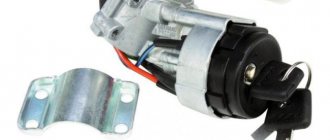
- Egnition lock;
- Circuit breakers;
- Switch;
- Spark moment sensor;
- Coil;
- Candles;
All elements are connected to each other by wiring.
Using the ignition switch, the driver controls the power supply to the system from a source - the battery, while the voltage passes through the auxiliary relay and fuses. The lock has three positions - “0”, in which all electrical consumers are turned off, “1” - voltage is supplied to the ignition system and a number of other devices, and “2” - current is supplied to the starter. This switching sequence ensures that the ignition system is activated at the moment the engine starts.
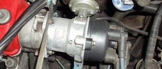
Spark torque sensor
The spark timing sensor is one of the main ignition components, since it sets pulses that are subsequently converted into a spark discharge between the spark plug contacts. This sensor is driven by the camshaft, which allows you to accurately set the timing of the spark in the cylinders.
The main working elements of the unit are the Hall sensor and a special screen with slots mounted on the drive shaft interacting with the camshaft. The interaction of these elements leads to the emergence of control impulses.
The sensor not only sets pulses, it also “adjusts” to the operating conditions of the motor, adjusting the advance angle depending on the operating conditions of the motor (speed, load).
The adjustment is carried out by two regulators - vacuum and centrifugal, included in the design of the spark generation moment sensor.
Until 1989, Oka used a sensor of type 55.3706, and after that it was replaced by model 5520.3706.
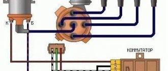
Switch
The switch acts as a circuit breaker for the primary winding of the coil, using control pulses coming from the spark sensor. Circuit interruption in the switch is performed by the output transistor. The switch is completely electronic, without any moving elements, so the ignition system is contactless.
Several types of switches were installed on the VAZ-1111 and 11113 - 36.3734, 3620.3734, as well as HIM-52. The switch is installed in the engine compartment near the engine panel. It is secured with two bolts, so replacing the switch is quite simple.
Coil
Oka received a two-terminal ignition coil, which made it possible to remove the distributor from the design.
It is noteworthy that the high voltage in this coil is supplied simultaneously to both spark plugs. Moreover, due to the offset strokes in the engine cylinders, only one spark discharge is working, the spark on the second spark plug is the so-called “idle”.
The standard coil on the Oka is type 29.3705, but it has an analogue that is suitable for use on a small car - 3012.3705.
Wires, spark plugs
All wiring consists of low and high voltage wires. The first ones are used to connect all the components up to the coil. These are ordinary wires of small cross-section, which is quite sufficient, since the voltage in the circuit up to the coil is low.
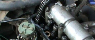
Oka gas distribution mechanism
If you compare old VAZ classic engines with a timing chain drive, you will notice significant differences in the design of the drive. The bulky metal chain was replaced with a timing belt. The design of the cylinder block has become shorter and lighter, since the opening for the chain in the timing drive mechanism has disappeared. The designers changed the principle of opening valves, it became simpler. If on old engines the camshaft cam pressed on the valve stem through the rocker arm, now it acts on it through the adjusting washer. The thermal gap is set on a cold engine by selecting a washer of the required thickness. Manufacturers make them in different sizes, the values of which are marked on the ends of the washer. If the driver adjusts the thermal gap independently, he will have to purchase a certain number of such washers, which is not always economically feasible.
The design of the timing mechanism drive is such that the belt drives the pump in the Oka engine cooling system. Often it is because of the breakdown of this pump that the toothed belt drive fails. Therefore, car manufacturers recommend that the belt drive and pump in the engine cooling system be replaced at the same time. When inspecting, you should pay attention to the condition of the tension roller in the timing mechanism.
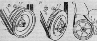
Belt replacement procedure
The process of replacing a timing belt on Oka is not very difficult. If you carefully study the process before doing this, you can do it yourself. The work can be done on any level surface.
Before starting the operation, install wheel chocks under the rear wheels and tighten the hand brake cable. The front wheels are turned to the right as far as possible (all the way), and the battery is disconnected. The further procedure will be something like this:
- In the engine compartment, remove the spare wheel and the windshield washer fluid reservoir. You will also have to dismantle the air filter housing and ignition coil.
- After loosening the tension on the generator set drive belt, remove it from the pulleys.
- After this, you can remove the protective plastic timing case.
- Next, rotate the crankshaft clockwise until all the timing marks in the timing drive are aligned.
- It is not yet possible to remove the toothed belt; the generator set drive pulley on the engine crankshaft is in the way. There is a hole on the right mudguard in the direction of travel of the car. A 19mm socket wrench is inserted into it to unscrew the bolt on the crankshaft pulley. Before doing this, you should secure the motor from turning. This can be done through a hole in the top of the flywheel housing by inserting a strong screwdriver or suitable pry bar between the flywheel teeth. An assistant should hold it.
- Unscrew the bolt securing the generator pulley and remove it from the shaft.
- Next, loosen the tension of the timing belt. To do this, you need a 17mm wrench to loosen the tension roller nut. If it is replaced, then completely remove it from the axle. There is an adjusting washer in front of the roller on the block side.
- If the pump in the engine cooling system is being replaced, drain the antifreeze and then remove it from the engine block.
- Remove the toothed belt. Important! The engine cannot be cranked after this, so as not to bend the valves.
- Carefully inspect the condition of the timing drive pulleys, clean them of possible contamination and traces of engine oil.
- Installing a new timing belt is done in the reverse order. Before this, carefully check once again how the timing marks in the timing drive mechanism match. At the end of the work, manually turn the engine several times, and again check how the marks match.
How it all works
The principle of operation of the ignition system is as follows: after turning the key to position “1” el. Energy from the battery is supplied to the ignition system components through the lock, fuses and auxiliary relay. In this case, high voltage pulses are not generated, since the spark torque sensor is not yet operational.
After activating the starter, the timing drive begins to rotate the camshaft, and accordingly the sensor shaft - the Hall sensor begins to interact with the screen, due to which control pulses are created.
Arriving at the commutator, these pulses interrupt the power supply circuit of the coil winding. When the power circuit is broken, a high voltage pulse is induced in the coil, which is transmitted through high-voltage wires to the spark plug, which leads to the formation of a spark between its electrodes.
Malfunctions
The simplified design of the ignition system and the absence of moving components ensures high reliability and ease of maintenance.
There are not so many malfunctions in the Oka ignition system:
- Switch failure;
- Hall sensor malfunction;
- Coil failure;
- Breakage or breakdown of wires, oxidation of contacts;
- Spark plug malfunction;
- Violation of the ignition timing;
Since the ignition system is directly involved in the operation of the engine, any malfunction in it immediately affects the performance of the engine - interruptions occur, the unit does not develop power, popping noises appear, or the unit simply does not start.
Diagnosis of a malfunction is carried out by visual inspection of the wiring and its connections, as well as by sequentially replacing all components with known good ones. A check using measuring instruments allows you to more accurately determine the faulty element.
The search for the problematic element is carried out from the candles. That is, first the presence of a spark is checked on them, then the high-voltage wires are inspected, and then the performance of the coil, switch, and Hall sensor is diagnosed.
The components of the ignition system are non-repairable, so if they break down they must be replaced.
Malfunctions and ways to eliminate them
In this article we will focus on the malfunctions that are inherent in the VAZ Oka. The ignition system is an electronic thing and something can break down in it quite unpredictably. It is also worth knowing that maintenance must be carried out on this element of the machine too. Usually the driver has thoughts like this: “Oh, what could happen there, a bunch of wires.” But wiping the commutator and coil from dirt will not be superfluous and will extend the life of these elements. Next, let's look at the main possible breakdowns and how to fix them yourself in the garage or on the road.
The first and most noticeable failure is the VAZ Oka engine that will not start. The first thing that can fail here is the ignition system. First, let's look at the switch, which receives pulses from a contactless sensor; here a signal may not be sent to the Hall sensor. You need to check the Hall sensor itself, however, you also need to look at all the wires, perhaps a contact has simply come loose somewhere. Or it just needs to be cleaned, which, by the way, serves as a reminder of the importance of maintenance.
If a break is found, you just need to replace the wire. Next, if this breakdown was not detected, you need to pay attention to the spark plugs and high-voltage wires. It is possible that the high-voltage wire is not tightly inserted into the distributor cover. The reason for the lack of ignition can also be the coil.
If faults are visually noticed in it, then it needs to be replaced. The most common cause of coil failure is a loosely connected high-voltage wire, which causes the plastic cover to burn out and damage the integrity of one of the windings.
There may also be an option when the engine does start, but does not work stably and stalls at idle. Here you need to check the ignition timing sensor and check the ignition timing against reference indicators. If necessary, you will have to adjust the torque. If this does not help or no violations are found in the ignition timing, then you need to unscrew all the spark plugs and use a feeler gauge to check the gap between the contacts. If the gap is too large, then you can fix it simply by lightly pressing the bent contact, that's all.
Setting the advance angle
Setting the ignition timing is the only operation that is performed in the ignition system.
A strobe light is used to set the angle correctly. The technology for performing the work is not complicated. The algorithm of actions is as follows:
- We connect the strobe to the power source and the tip of the spark plug of the 1st cylinder (according to the instructions for the device);
- Remove the plug from the inspection window on the clutch housing;
- We start the engine (it should be idling);
- We direct the beam of light from the strobe into the viewing window;
- We determine the position of the marks (with the angle correctly set, the mark on the flywheel at the moment the strobe light beam flashes should be located between the central and rear marks on the crankcase);
- If the marks are not positioned correctly, make adjustments. To do this, loosen the bolts securing the spark moment sensor and rotating it around its axis until the marks match;
After adjustment, tighten the sensor fasteners, turn off the engine, disconnect the strobe light and replace the plug.