If you were unable to start your car and after checking the spark on the spark plug, it turned out that there was simply no spark, then you should check the entire ignition system of the VAZ 2106 and find a malfunction of a specific element.
In personal practice, I have had several cases that were accompanied by loss of spark. And then I will give them and talk about each in more detail.
Again, I will make a reservation that this is not a complete list of all the problems that can cause it, but I will try to list most of them. For experienced owners, you can supplement your thoughts by
One of the spark plugs is faulty
If, when checking a spark plug, a spark does not appear between the electrodes, then the first thing to do is check the spark plug itself. It is possible that this was the cause of this problem. Take a working spark plug (it’s better to always carry a spare one with you) and crank it a little with the starter. Observe the performance of the candle. If a spark appears, great; if not, you should look for the cause further. Also, you can see the problems that cause the spark to disappear here: https://atlib.ru/blog/164-net-iskry
How to carry out repairs
If a breakdown is detected, the damaged coil must be removed. To complete the work you will need a set of wrenches.
After installing the new module, engine operation is checked; additional ignition settings are not required.
Removing the module
To remove a faulty unit, you will need:
- Disconnect the battery from the on-board network and remove the air filter housing.
- Disconnect the high-voltage cables and wiring harness.
- Remove the 3 nuts that hold the assembly to the mounting pad.
Failure of high-voltage spark plug wires or the central wire of the ignition coil
If there is no spark on any one cylinder, then try swapping the high-voltage wires. When after this the operation of the previous cylinder was restored, but the other cylinder, on the contrary, stopped working, this indicates a failure of the spark plug wire.
If a spark does not reach any of the VAZ 2106 spark plugs, then you should check the integrity and functionality of the central wire. This can be done in a similar way as I wrote in the last paragraph. Also, you should just try to stick the wire harder into the coil and the distributor cover. Perhaps the wire has just jumped out a little in one of these places and there is no necessary contact.
Checking the quality of the ignition switch installation
First of all, the changes affected the engine management system and control instruments. In particular:
- The wiring diagram for Niva 21213 received an additional wiring harness in the engine compartment for connecting a microcontroller and sensors;
- On the Niva model of recent years of production, a more advanced power unit with the VAZ-21214 index is installed. Instead of a carburetor, it has a fuel frame with injectors from GM. The price of a car with injection has increased because of this;
- The instrument panel has changed - the design is borrowed from the VAZ 2108 model.
The operation of the Niva 21213 system depends on the condition of its parts. High-voltage wires must have a distributed resistance, the value of which is in a certain range. Too much resistance will result in the ignition coil not having enough power to cause a breakdown. Low resistance increases interference.
The high temperature inside the cylinders greatly heats the spark plugs. Therefore, even when the ignition is turned off, ignition occurs from heated spark plugs.
It is important that all spark plugs have the correct gap between the electrodes. This will ensure high-quality ignition of the mixture. The distributor cover must be clean from dirt, since its presence can lead to current leakage.
Read news about the new Niva
- Removing the fuel tank. VAZ 21213, 21214 (Niva)
- Niva 21214 clutch malfunction
- FROST car air conditioners // Online store // Prices // Air conditioners for cars Lada VAZ, VolksWagen Polo, Daewoo Matiz
- Removing the engine from the car. VAZ 21213, 21214 (Niva)
- Ignition relay Niva Chevrolet where is it located
- How to connect a speed sensor in a field
- Phase sensor Niva Chevrolet symptoms of malfunction, DPRV high signal level
- Chevrolet Niva won't start: reason, what to do?
Failure of the switch or hall sensor and no spark
This item applies to owners of a VAZ 2106 with electronic ignition. If there is no spark, then these two elements can cause this disaster. It is necessary to diagnose the malfunction of these parts and replace them with new ones if necessary.
If you have a BSC installed on your VAZ 2106, then you can carry a hall sensor with you as a spare. Which, in fact, is the most common cause of malfunction. Or, as a last resort, do like me. Carefully fold the old contact ignition kit and let it lie in the trunk. It doesn't take up much space, but it can help you out a lot somewhere on the road. For example, if one of the BSZ elements burns out!
If any of the owners have encountered other reasons for the disappearance of the spark, then please share in the comments. I think that for many owners this information will be very useful!
We carry out the adjustment ourselves
- The first step is to install the cylinder in the correct position. Installation is carried out so that the mark on the pulley is exactly at 0 degrees.
- Set how the slider is positioned. It should be aimed at the first pin in the cylinder.
- Use a strobe light and make sure the ignition is working properly.
- Make the electrical connections in the battery: minus to ground, plus to plus.
- The sensor must be connected to the high-voltage wire on the cylinder. The mark should connect to the crankshaft pulley.
- Start the engine at low speed (up to 800 rpm). Use a stroboscope to illuminate the pulley, and if the mark coincides with the middle mark, then the ignition is set correctly.
- Otherwise, the engine should be turned off and the meter should be loosened. In order to decrease the angle, turn the sensor clockwise; to increase it, turn it counterclockwise. Record and test the calibration again with the ignition on.
- Next, you should perform manipulations with the distribution sensor. Open the lid. Match the stator and rotor mark.
- Start the engine, bring the temperature to 75-80 degrees. When the speed is 50 km/h, sharply press the gas pedal.
- If the ignition was installed correctly, a short-term detonation will occur when you press the gas.
Also interesting: Chevrolet Niva fan does not turn on
Then there are two possible developments: early and late ignition. Let's consider solutions for both cases:
- In the case of late ignition, when there is no detonation, you should change the position of the sensor clockwise.
- In the case of early ignition, when detonation lasts longer than necessary, the sensor is rotated counterclockwise.
Niva 21213 can be subject to adjustment of the starting system by the gap at the edges of the valves, if the carburetor is removed, or by the crankshaft speed directly on the car. In the first case, the gap at the location of the lower edge (in the direction of air movement) from the throttle valve is set to a width of 1.1 mm.
It is adjusted with a screw that has a 0.7 cm hexagon on the head and a slot from the shank. This operation is carried out with the cam lever turned counterclockwise from the starting system control (all the way). In the same position, the gap at the lower edge of the air damper is set to 3 mm using a screw in the cover from the diaphragm mechanism in the starting system (you need to loosen the lock nut).
The principle of powering a carburetor engine Adjusting the Niva starting system directly in the car saves time: You need to remove the air filter from the engine, pull the control lever towards you from the air damper, and start the engine. When the air damper is forced to open (by touching a flat screwdriver to a third of its full angle of rotation) using a screw (next to the lever on the axis from the throttle valve from the first chamber), the initial rotation speed is set to 2.08.mar.0 thousand.
revolutions per minute (on a warm engine). Remove the screwdriver, lower the air damper and, using the screw stop (next to the diaphragm), set the frequency to be 100 rpm lower than the original one (you need to select the appropriate position of the air damper). The screw can then be secured using a locknut.
If you have a gas analyzer, then the carburetor adjustment in the starting system part can be done based on the amount of CO (carbon monoxide) in the exhaust gases. If, with the choke control lever fully extended, the gas rate is 8%, then everything is in order. If there is less gas than this value, then the screw on the cover of the diaphragm mechanism is tightened; if there is more, it is unscrewed and repeated measurements are taken.
It is necessary to adjust the idle speed of the Niva 2121 so that there is less carbon monoxide in the exhaust gases and so that the engine runs stably. At service stations, such work is carried out with gas analyzers on the MV. In the garage, adjustments can be made using the tachometer.
Adjusting the device For these purposes, on a warm engine, pierce the plastic plug with a screwdriver, then the quality screw is rotated in different directions until the maximum idle speed is reached. Then, using the quantity screw (has a ribbed plastic handle), you need to set an increased speed (50-70 rpm.
VAZ 21213 no spark on the center wire
Part two - the engine starts, but does not run satisfactorily.
Necessary preconditions: 1) the engine is in good working order; 2) the marks of the crankshaft and camshaft match; 3) gasoline and air enter the suction manifold from the carburetor; 4) there are no barriers to the escape of exhaust gases (no one’s “kind hand” stuck a potato into the muffler);
Step one: check for spark from the ignition coil. How to check it alone: 1. Gearbox in neutral; 2. pull out the central wire from the distributor and fix the metal tip of this wire at a distance of 5-7 mm from the ground (it is convenient to squeeze the insulating cap between the brake cylinder and the outlet tube); 3. turn on the ignition; 4. remove the block with wires from the starter relay and short-circuit the thick wires in it (perpendicular to each other) with a jumper - the starter will work; At this moment, a spark will (should) begin to beat rhythmically from the main wire. If there is no spark at all, read step two. If the spark is weak and begins to skip with a slight increase in the air gap (up to 10-12mm), read step six. In passing, I note that an indicator of the reliability of a starting spark is its continuity and length (and not color and thickness).
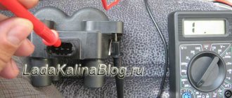
How to check the ignition coil of a VAZ with a multimeter, checking the circuit?
The first thing you need to decide is whether the coil is not working or something in front of it. To do this, take the terminal from the ignition coil in one hand and a milliliter in the other hand and begin testing. Although, before I continue my story, you probably need to familiarize yourself with the pinout of the wires. Therefore, look carefully at the following picture.
Now I’ll explain the picture, we have 4 wires, 2 signal wires, one ground and one power. You need to check all 4 wires, let's start in order; by the way, the pinouts A, B, C, D are not marked on the plug itself. Let's start checking with the power cable. Turn on the ignition, connect one multimeter probe to the negative terminal of the battery, and the other to terminal D. The voltage should be 12 volts.
My test shows 11.86 volts, now we know that voltage is coming to the coil. Next, let's check the ground; this is pin number C; for this, we connect the multimeter probe to pin C and the other to the positive terminal of the battery.
There is also contact with the ground. We can check both wires at once by connecting a milliliter to pins C and D, the voltage should also be 12 volts. Let's move on to checking the signal wires. A and B To do this, switch the multimeter to resistance measurement mode.
I stuck the wires in from different sides because it was impossible to hold everything in place with one hand. My multimeter showed 1.17 kOhm, sources on the Internet say that the resistance should be below 1 kOhm, most likely something, somewhere, has oxidized, by and large, it wouldn’t be a bad idea to start figuring it out, maybe there are problems in the ECU, but today we’re dealing with ignition coil.
Total: we found out that the voltage to the ignition coil comes with the signal wires, and everything is in order. So we move on to the ignition coil itself.
No spark on VAZ 2106
Sparking is an important process that ensures the startup and stable operation of the power unit, for which the ignition system is responsible. The latter can be contact or non-contact, but the essence of its work remains the same - to ensure the formation and distribution of a spark to the desired cylinder at a certain point in time. If this does not happen, the engine may either not start at all or run intermittently. Therefore, it is worth dwelling in more detail on what kind of spark there should be and what the reasons for its absence may be.
Purpose and design of the part
The purpose of this sensor is one thing - to supply a reliable spark to the combustion chamber of the car through high-voltage wires and a spark plug. To be more precise, the ignition module does not supply a spark, but only the voltage necessary to form a spark on the spark plug.
The design of the part is made of heat-resistant plastic, in which two coils are placed. Each of the coils is responsible for the operation of two cylinders. The coils have a primary and secondary winding in which high voltage is generated.
Module differences
There are two types of ignition modules for Niva. The first type was installed on Niva until 2006, and it migrated to the Lada 4x4 from the VAZ 2112.
VAZ 2112 module
The Niva received a new type of module from the VAZ 2111.
VAZ 2111 module
Visually, these two details are quite difficult to confuse. They differ from each other in weight and dimensions; the weight of the MZ from the VAZ 2112 is much greater than from the VAZ 2111.
Troubleshooting
Troubleshooting in the ignition system of the VAZ “Six” should be carried out using the method of elimination, checking element by element sequentially. This is worth dwelling on in more detail.
Battery check
Since when starting a car, the power source is the battery, it is by checking this device that diagnostics should begin. Malfunctions with the battery appear when you try to start the engine. At this moment, the indicator lights on the instrument panel go out. The reason could be either poor contact on the terminals themselves, or simply a weak battery charge. Therefore, the condition of the terminals should be checked and, if you need to clean them, tighten the fastening. To prevent future oxidation, it is recommended to cover the contacts with a graphite coating. If the battery is discharged, it is charged using an appropriate device.
Spark plug wires
The next elements that require mandatory checking in case of problems with sparking are explosive wires. Upon external inspection, the cables should not show any damage (cracks, breaks, etc.). To assess whether a spark passes through the wire or not, you will need to remove the tip from the spark plug and place it near a ground (5–8 mm), for example, near the engine block, and crank the starter for a few seconds.
At this time, a powerful spark should jump. The absence of one will indicate the need to check the high-voltage coil. Since it is impossible to determine by ear which of the cylinders does not spark, the test should be performed one by one with all wires.
Video: diagnostics of explosive wires with a multimeter
Spark plug
Spark plugs, although infrequently, still fail. If a malfunction occurs, it is with one element, and not with all of them at once. If a spark is present on the spark plug wires, then to check the spark plugs themselves, they are unscrewed from the cylinder head of the “six” and an explosive cable is put on. The metal body of the spark plug touches the masses and turns the starter. If the spark plug element is working, then a spark will jump between the electrodes. However, it may also be absent from a working spark plug when the electrodes are filled with fuel.
Malfunctions and solutions
As a rule, most malfunctions occur due to the fault of spark plugs and high-voltage wires. However, other reasons cannot be ruled out. In non-contact systems, you cannot disconnect the terminal from the battery to check the operation of the generator. Otherwise, the switch may fail. A malfunction of the ignition coil can be determined by measuring the resistance of its windings. Replace with a suitable one. A coil from a contact system will not work, because its parameters are different. The commutator can be checked by examining its pulses to the coil. In this case, all conditions are necessary to ensure its operation. For example, the health of the Hall sensor. The easiest way to check spark plugs is to replace them with ones that are known to work with the same gap and preferably of the same type. Burnt distributor contacts and jammed carbon contribute to deterioration of spark formation.
Therefore, it is necessary to carry out a visual inspection at least once a year. Some engine malfunctions are not necessarily caused by ignition problems.
In addition, it is worth paying attention to the correct setting of the lead angle. Some experts do not believe the strobe data and rely on engine operation in different modes. If piston pin sounds are heard, this indicates that the advance angle needs to be reduced.
Checking the contact distributor
The need to check the distributor-breaker arises if problems arise with sparking, but during the diagnostics of the ignition system elements the problem could not be identified.
Cover and rotor
First of all, we inspect the cover and rotor of the device. The check consists of the following steps:
- We dismantle the distributor cover and inspect it inside and out. There should be no cracks, chips, or burnt contacts on it. If damage is found, the part must be replaced.
contact Group
The main malfunctions of the ignition distributor contact group are burnt contacts and incorrect clearance between them. In case of burning, the contacts are cleaned with fine sandpaper. If they are severely damaged, it is better to replace them. As for the gap itself, to check it it is necessary to remove the cover of the distributor-breaker and turn the engine crankshaft so that the cam on the distributor shaft opens the contacts as much as possible. We check the gap with a feeler gauge and if it differs from the norm, then we adjust the contacts by unscrewing the corresponding screws and moving the contact plate.
Capacitor
If a capacitor is installed on the distributor of your “six”, then sometimes the part can fail as a result of a breakdown. The malfunction appears as follows:
- problems starting the engine;
- sudden engine stop while driving.
You can check an element in the following ways:
- Control lamp. Disconnect the wiring coming from the coil and the capacitor wire from the distributor according to the figure. We connect a light bulb to the open circuit and turn on the ignition. If the lamp lights up, it means that the part being tested is broken and requires replacement. If not, then it's OK.
Device and connection diagram
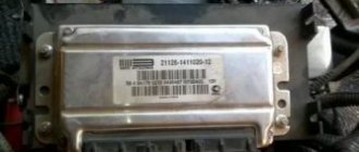
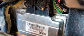
Inside the ignition system module (catalog number 2111-3705010) there are voltage converters and electronic components that distribute pulses based on signals from an external sensor. The elements are connected by jumpers, which are attached with tin-lead solder. The housing is made of dielectric material that does not collapse under the influence of vibrations and temperature changes. The outputs are equipped with contact plates to which mating elements of high-voltage cables are connected.
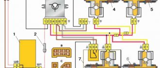
Ignition system diagram.
Connection instructions
Switching algorithm:
- Install the coil onto the cylinder block and secure with screws.
- Connect the plug of the engine wiring harness.
- Connect the outputs of the coil to the spark plugs with high-voltage wires, observing the serial numbers of the cylinders. The numbers are printed on the module body. On the engine, the cylinders are counted from the accessory drive pulley.
- Connect the battery and crank the crankshaft with the starter to start the engine.
Checking the contactless distributor
If the “six” is equipped with a contactless ignition system, then checking elements such as spark plugs, coil, and explosive wires is performed in the same way as with a contact one. The differences lie in checking the switch and the Hall sensor installed instead of the contacts.
Hall Sensor
The easiest way to diagnose a Hall sensor is to install a known working element. But since the part may not always be at hand, you have to look for other possible options.
Checking the removed sensor
During the test, the voltage at the sensor output is determined. We determine the serviceability of the element removed from the machine according to the presented diagram by applying a voltage in the range of 8–14 V.
By placing a screwdriver in the gap of the sensor, the voltage should change within 0.3–4 V. If the distributor has been completely removed, then by turning its shaft, we measure the voltage in the same way.
Checking the sensor without removing it
The performance of the Hall sensor can be assessed without removing the part from the car, using the diagram provided.
The essence of the test comes down to connecting a voltmeter to the corresponding contacts on the sensor connector. After this, turn on the ignition and turn the crankshaft with a special key. The presence of voltage at the output, which corresponds to the above values, will indicate the serviceability of the element.
Video: Hall sensor diagnostics
Switch
Since the formation of a spark also depends on the switch, you need to know how to check this device too.
You can purchase a new part or perform the following sequence of actions using a control light:
- Unscrew the nut and remove the brown wire from contact “K” of the coil.
- We connect a light bulb to the resulting open circuit.
- Turn on the ignition and crank the starter several times. If the switch is working properly, the light will light up. Otherwise, the element being diagnosed will need to be replaced.
Video: checking the ignition system switch
The performance of the systems and components of the VAZ “six” must be constantly monitored. The occurrence of problems with sparking will not go unnoticed. Troubleshooting and troubleshooting does not require special tools or skills. A minimal set consisting of keys, a screwdriver and a light bulb will be quite sufficient for diagnostics and repairs. The main thing is to know and understand how a spark is formed, and what elements of the ignition system can affect its absence or poor quality.
Non-contact ignition system device
Contact ignitions are obsolete, but are still used in older cars.
On rear-wheel drive VAZ models, contactless was first installed on 2107. The BSZ device for carburetor engines consists of:
- Distributor. This is a device that is responsible for creating a spark at the right moment. It is also called the ignition system distributor.
- High voltage coil. This element in the ignition system receives low voltage from the battery, converts it and supplies high voltage. Therefore, high-voltage wires come from it. The coil consists of two windings. The primary one is made of a large cross-section wire (connected to the electrical part of the car via the ignition switch relay), the secondary one is made of many turns of thin wire (connected with a high-voltage wire to the distributor).
- Switch. This element of the contactless ignition system is responsible for the formation of a spark. In simple words, a switch is a signal amplifier. The switch is only available in the ignition system of internal combustion engines with a carburetor. By the way, SOLEKS is considered the best carburetor. On injection VAZ 2107, as well as on others, a switch is not needed, since its functions are performed by the on-board computer controller.
- High voltage and normal wiring. High voltage wiring must meet heavy insulation requirements.
- Terminals. Serve for connections and must be strong.
https://www.youtube.com/watch?v=SqqIBAU8osQ
Electronic and contactless ignition systems are the same device. It got its name due to the absence of a contact group in the system design. The ignition switch also has a contact group, which is a common cause of engine failure.
To install the BSZ with your own hands, you will need the following tools:
- Screwdrivers (flat and Phillips);
- Open-end wrenches 8, 10, 13 mm;
- Pliers (pliers);
- Candle key;
- Drill or screwdriver with a drill diameter of 3-3.5 mm. You will have to drill two holes in the body to secure the switch.
- A special wrench for rotating the crankshaft of an internal combustion engine or a regular open-end wrench of 30 mm.
This video covers all the nuances.
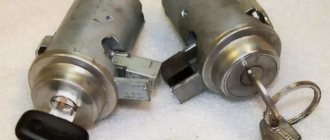
First of all, it is important to make sure that the problem is in the lock. Therefore, the spark plugs, distributor and ignition coil are inspected. Often these parts of the internal combustion engine become the reason for failures of correct operation. If breakdowns in them are excluded, then the ignition switch (IZ) should be replaced. Removal order:
- Disconnect battery.
- Remove the steering column.
- Mark the wires going to the 3Z contact area. Using a flat-head screwdriver, unscrew the bolts securing the switch to the steering column (left and right).
- Insert the key into position 0. By pressing the screwdriver, press the lock slightly through the hole (do not touch the key).
- Lightly pull the 3Z towards you and dismantle it. The ignition switch Niva 21213 is switched off according to the wiring diagram (the contact part is changed if required). To do this, be sure to remove the retaining ring with a screwdriver.
- Remove the key, install the contact part so that the wide protrusions of the body and the parts coincide.
- The remaining parts are assembled in the reverse order.
If you strictly follow the instructions and wiring diagram, no problems should arise. This is facilitated by the simplicity of the design. Moreover, the part can even be repaired if the damage is not critical.
It is logical that errors are possible when connecting contacts or incorrect installation of the lock itself. Therefore, it is necessary to test the protection in the installed state. You will need an ohmmeter and a voltmeter. Performance diagnostics:
- Checking the resistance between the terminals of the secondary winding: connect the probes to cylinders 1 and 4, then to cylinders 2 and 3. The data should approximately match. An error greater than 100 ohms indicates damage to the secondary winding.
- The wiring is checked with a voltmeter. The first control - one probe is placed on contact A, the second - on ground. Start the engine and record the data. Turn off the car and repeat the procedure with contact B. The readings should be about 12 volts.
- In addition, if there is no voltage, check the fuse, the possibility of broken wiring or corrosion of the contacts.
The last case is especially unpleasant, since you will have to check almost all the wiring, contact elements, etc. If there are possible suspicions about the electrical network, it is better to take the car to a professional auto electrician. Repairing it requires a thorough knowledge of the circuit and experience in finding defects.
| №1 | Rear fog lamp relay |
| №2 | Rear window heating relay |
| №3 | Low beam relay |
| №4 | High beam relay |
Some owners of classic cars of the VAZ 2101-07 family are constantly trying to improve, modify, add electronics and convenience. One of these improvements is the installation of contactless electronic ignition.
- Distributor. This is a device that is responsible for creating a spark at the right moment. It is also called the ignition system distributor.
- High voltage coil. This element in the ignition system receives low voltage from the battery, converts it and supplies high voltage. Therefore, high-voltage wires come from it. The coil consists of two windings. The primary one is made of a large cross-section wire (connected to the electrical part of the car via the ignition switch relay), the secondary one is made of many turns of thin wire (connected with a high-voltage wire to the distributor).
- Switch. This element of the contactless ignition system is responsible for the formation of a spark. In simple words, a switch is a signal amplifier. The switch is only available in the ignition system of internal combustion engines with a carburetor. By the way, SOLEKS is considered the best carburetor. On injection VAZ 2107, as well as on others, a switch is not needed, since its functions are performed by the on-board computer controller.
- High voltage and normal wiring. High voltage wiring must meet heavy insulation requirements.
- Terminals. Serve for connections and must be strong.
And also interesting: Connection points for the Niva Chevrolet alarm system.
The ignition system is contactless. Consists of a distribution sensor, switch, ignition coil, spark plugs, ignition switch and high and low voltage wires.
The ignition distributor sensor 3810.3706 is a four-spark type, with a contactless control pulse sensor and built-in vacuum and centrifugal ignition timing regulators.
The initial ignition timing angle at a crankshaft speed of 750–800 rpm should be 1±1° BTDC.
The distribution sensor performs two main functions: firstly, it sets the moment of spark formation depending on its initial setting, the number of revolutions of the crankshaft and the load on the engine, and secondly, it distributes high voltage pulses (“spark”) among the cylinders in accordance with the order of their operation - a rotor (runner) is used for this.
In order to avoid mistakes during assembly, the slider is installed on the support plate of the centrifugal regulator in only one position.
The slider has a 1 kOhm noise suppression resistor.
The operation of a contactless sensor is based on the Hall effect.
When the ignition is turned on, power supply is supplied to the sensor. When the sensor-distributor roller rotates, a steel screen with rectangular cutouts passes through the sensor gap.
While there is a screen plate in the gap, the voltage is removed from the control terminal of the sensor; as soon as there is a cutout in the gap, the voltage at the control terminal drops sharply.
Thus, the contactless sensor produces four rectangular pulses (according to the number of cutouts in the screen) for each revolution of the distributor shaft, which corresponds to the ignition moment in each of the engine cylinders.
You can check the functionality of the contactless sensor by assembling the circuit shown in the figure.
Slowly rotating the ignition distributor shaft, monitor the voltmeter readings.
The voltage should change sharply from the minimum (no more than 0.4 V) to the maximum (no more than 3 V less than the supply voltage).
A faulty sensor cannot be repaired (except for a break in the wires between the sensor itself and the block on the sensor-distributor housing).
If a steel screen with slots touches the sensor (determined by slight jamming or a scratching sound when the roller rotates, as well as visually after partial disassembly of the distributor sensor), check the axial play of the roller and the fit of the screen.
If necessary, replace the distributor sensor. The centrifugal regulator increases the ignition timing with increasing engine speed, coming into operation at 900–1400 rpm.
When the sensor-distributor roller rotates, the regulator weights diverge under the action of centrifugal forces, overcoming the resistance of the springs, and shift the support plate of the centrifugal regulator clockwise relative to the roller.
For optimal operation of the regulator, the springs have different stiffnesses.
A stiffer (thicker) spring comes into operation later, approximately in the middle of the full stroke of the plate - therefore it is put on the stand with a gap, while a softer (thin) spring is always tense.
The maximum movement of the support plate is limited by the cutout in it and is about 12° along the distributor, which corresponds to an ignition timing angle of about 24° along the crankshaft.
When inspecting the centrifugal regulator, make sure that the weights move freely on the axles, their damper plastic rings are not lost, the thin spring is tensioned, and the support plate returns under the action of the springs to its original position. If necessary, lubricate the distributor shaft with a few drops of engine oil.
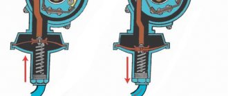
The vacuum regulator increases the ignition timing depending on the engine load. It consists of a vacuum chamber with a steel spring-loaded membrane, which is connected by a rod to the base plate of the proximity sensor.
Under the influence of vacuum, the membrane bends, overcoming the resistance of the spring, and turns the support plate counterclockwise.
The maximum movement is limited by the cutout on the rod and is about 9° at the distributor (18° at the crankshaft).
The vacuum for the operation of the vacuum regulator is taken from the hole in the mixing chamber of the carburetor opposite the throttle valve of the first chamber. When the damper is partially opened (partial load), the vacuum behind it is large, and the regulator shifts the moment of spark formation as much as possible towards the advance.
