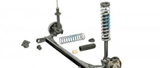
The rear suspension is dependent, with 12 coil springs and 10 double-acting hydraulic telescopic shock absorbers.
The main load-bearing element of the suspension is a beam consisting of trailing arms 14 and a connector 13, welded together through reinforcements.
At the rear, brackets 15 with eyes for attaching shock absorbers 10 and flanges for attaching the rear wheel axles and brake shields are welded to the suspension arms.
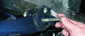
At the front, the levers 14 are equipped with welded bushings with silent blocks 3 pressed into them. A bolt passes through the central bushing of the silent block, connecting the lever to the bracket 2.
To attach the bracket to the body side member, three welded bolts are provided.
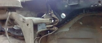
The suspension spring 12 rests with its lower end on a cup welded to the shock absorber reservoir, and with its upper end, through a rubber gasket 11, on a support welded from the inside to the body arch. The lower eye of the shock absorber is bolted to bracket 15 of the suspension arm, and its rod is secured to the upper support of the suspension spring through two rubber pads 8 (one at the bottom of the support, the other at the top) and a support washer 7 (under the nut).
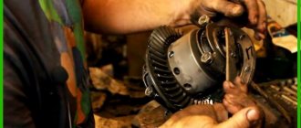
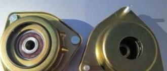
The hub has a double-row angular contact ball bearing, similar to the front wheel hub bearing, but smaller.
The bearing fit on the axle is transitional (with slight interference or clearance).
During operation, the bearing does not require adjustment or replenishment of lubricant. It is not allowed to eliminate the resulting play by tightening the nut; the bearing should be replaced.
When the hub is pressed out, the bearing is destroyed, so it is not recommended to disassemble the hub if the bearing is in good condition.
Rear beam device
The metal rear beam, a photo of which is presented on our resource, is structurally represented by 2 longitudinal levers and connection elements, which are connected by welding through reinforcement components. At the rear of the product there are special holders with holes for mounting shock-absorbing elements. There are also flanges with holes for fastening the axles of the rear wheel pair together with the casings of the stern brake systems.
In the front part of the rear axle beam of the VAZ 2110 there are levers with welded bushings, in which rubber-metal type hinges are installed by pressing. The rear beam mounts pass through them, which connect the lever part of the stern suspension to stamped-welded type holders. Those, in turn, are mounted with welded bolts to the body side members.
The spring elements of the suspension rest with one plane on the support of the shock absorber strut, and with the other, through a rubber insulating gasket, into the welded support of the hidden arch of the body tail. The shock absorber strut of the rear suspension beam of the VAZ 2110 is a hydraulic telescopic system of a two-way operating principle.
Through fasteners in the form of a bolted connection, it is articulated with the holder of the longitudinal-type stern suspension arm. The upper fastener of the rack is made in the form of a pin connection, while the fastening of the rod to the upper support is made through rubber pads and a support washer.
The factory “tens” rear beam, the dimensions of which differ from the parameters of similar products, has the item number 2110-2914008, while the “eight” beam has the catalog number 2108-2914008-10.
Garage or service station
All car owners can be divided into two categories:
- Those who carry out most of the repairs themselves in their garage, and only in emergency cases turn to a car service;
- Those who prefer not to touch anything with their own hands, but completely entrust repairs and maintenance to the masters of service stations.
Each of them is right in their own way. Therefore, we have no right to reproach those who do not want to carry out repairs themselves. After all, garage and professional repair of silent blocks, like other components, has its advantages.
STO has the following advantages:
- A high-quality, responsible car service provides a guarantee for repairs performed;
- In the event of a repeated breakdown covered by the warranty, repairs will be carried out free of charge;
- Professionals are professionals; they have extensive experience and knowledge, which allows them to competently perform their work.
But first you need to find such a car service, which, alas, is not an easy matter. Many provide a guarantee, but when you re-apply, they do everything possible to prove that the breakdown does not comply with the terms of the guarantee. A banal trick.
Repairing your garage will provide the following advantages:
- Significant financial savings, since you only have to spend money on consumables;
- The quality of the work performed by a master is always in doubt if you do not know this person personally. So self-repair may be much better than at a service station;
- You purchase the silent block, and the master only installs it. Why pay money for work that you can do yourself?!;
- Guarantee that a new one will be installed instead of the old silent block. Questionable service stations can easily install an old, more or less usable silent block instead of the one you gave them. You know what the result is.
Here are the benefits you can get:
- Firstly, such a procedure will cost much less than at a car dealership.
- Secondly, it is not known how well the master will complete everything. After all, it’s no secret that very often they do everything badly, so that they will soon be turned to for help again. Of course, there are also conscientious car mechanics, but this is rare.
- In any case, you will need to purchase a silent block yourself and give it to the master. At the car dealership he will only install it. That is, payment will only be made for work that you can do yourself.
- And finally, no one knows whether the master will install a new silent block or will make do with some old one that still functions.
Removing and installing the rear beam and its elements
If during the operation of the vehicle the rear suspension beam of the VAZ 2110 bursts, then in the future it will need to be replaced. Of course, as a temporary aid, it can be restored by welding. But this is done solely in order to get to the maintenance site where it needs to be replaced.
Operating a vehicle with a welded beam rear suspension of the VAZ 2110 not only creates an emergency situation on the road, but also leads to disruption of vehicle stability and accelerated wear of the vehicle tires. The market value of the rear beam is quite high, but its replacement in this case is simply necessary.
We replace a product such as a rear beam, which can be purchased at any specialized automotive store, according to the following scenario:
- We place the vehicle on an electric lift or a special repair pit.
- We remove the brake pads from the rear wheels and release the hand brake cables from the rear beam and holders.
- We remove the brake pipes from the rear cylinders, and the hoses from the stern beam.
- We remove the drive-type pressure regulator fasteners from the stern beam.
- Remove the 4 bolts securing the hub axle to the aft beam using a wrench set to “17”.
- We dismantle the hub axle together with the brake mechanism casing.
- Having removed the fastening bracket, we dismantle the brake system pipe.
- If the need arises, we disconnect the hub axle and the brake mechanism housing, while freeing 2 screws with a curly screwdriver.
- We detach the lower fasteners of the shock absorbers from the rear beam.
- Remove the fasteners of the rear suspension beam to the holders.
- Place the rear beam on the ground.
- Having removed the fasteners, we dismantle the product.
- We remove the fasteners of the holder to the bodywork and dismantle the bracket.
- Installing the rear suspension component is carried out in the reverse order.
- We complete the fastening of the rear beam and the lower part of the shock absorber struts with the vehicle installed on the site.
- We finish the job by bleeding the brake system.
And now the procedure for replacing the silent block:
1. Unscrew the fastening nuts from the bolts of the stern beam, remove the retaining bracket on the left and disconnect the control brake rod. 2. We release the bolt from the technological hole and slightly raise the vehicle on a jack, moving the beam eye to the lower plane. We use a wooden beam as a spacer between the body surface and the rear beam. 3. Press out the silent block of the rear beam using a puller or drift. 4. We lubricate the working surfaces of the product and the eye with a solution that facilitates its installation, and press the product into place. 5. We take out the beam, use another jack to coaxially install the rear installation beam eye with the bracket and secure it with fasteners. 6. We tighten the stern beam fasteners on the car removed from the lifting mechanisms.
The selection of rear beam silent blocks for the VAZ 2110 is carried out in accordance with the item number 2110-2914054. The fundamental difference between these products and similar spare parts from the VAZ model range is the size of the outer diameters of the product. The standard silent block of the rear beam, which can be replaced on an electric lift or on an overpass or driver's pit, is purchased at auto stores using the appropriate catalog code.
Watch the video:
- < Central locking for VAZ 2106 and its installation
- What is the best way to replace the rear struts of a VAZ 2110 >
Removing the rear suspension beam VAZ 2110,2111,2112 – watch video online in My World
My homeland))))) Super top 106,497 11/24/2017 Well, we parted ways) Super top 77,488 11/24/2017 Multi-colored lakes) Super top 12,450 11/24/2017 How to get close to a chicken unnoticed) Super top 23,626 11/24/2017 Fable. Dog and an inverted cup) Super top 14,820 11/24/2017 Meeting of accordionists) Super top 8,692 11/24/2017 Baby gecko) Super top 7,378 11/24/2017 When you're tired of dieting))) Super top 5 901 11/24/2017 When you prepare food according to a recipe bloggers) Super top 4,926 11/24/2017 When you're in a video game) Super top 4,145 11/24/2017 When you forget basic things) Super top 4,543 11/24/2017 When you don't want to part with something you love) Super top 4,495 11/24/2017 Oops ) Super top 4,002 11/24/2017 Start and continue) Super top 3,166 11/24/2017 Positive)) Super top 2,975 11/24/2017 Little children and a dog are completely positive Super top 2,406 11/24/2017 Children and dolphins. Super top 1,729 11/24/2017 And everyone would think a UFO) Super top 1,757 11/24/2017 The last waltz of autumn Super top 1,039 11/24/2017 Extract from the maternity hospital. This needs to be seen and heard Super top 1,737 11/24/2017 A stubborn puppy and a treadmill Super top 1,568 11/24/2017 A child eats to the beatbox rhythm Super top 1,746 11/24/2017 A husband needs it Super top 1,480 11/24/2017 Italians' reaction to Yeralash Super top 933 11/24/2017 Gorilla adopted a boy Super top 1 902 11/24/2017
Removal and installation of the rear beam VAZ 2110, VAZ 2111, VAZ 2112
Rear beam Installation and repair of the rear suspension of VAZ 2110, VAZ 2111, VAZ 2112 do-it-yourself chassis repair rear suspension, do-it-yourself check, repair
We carry out the work on an inspection ditch or a lift.
We remove the rear brake pads of the VAZ 2110 and disconnect the parking brake cables from the rear suspension beam and brackets. Disconnect the brake pipes from the rear brake cylinders, and the rear brake hoses from the beam. We disconnect the elastic lever of the pressure regulator drive from the beam (see chapter Brake system VAZ 2111).
Using a 17mm wrench, unscrew the four bolts securing the hub axle to the rear suspension beam.
We remove the hub axle together with the brake shield of the VAZ 2111.
Having unbent the fastening bracket, remove the brake pipe.
If necessary, separate the hub axle and the brake shield by unscrewing two screws with a Phillips screwdriver.
Brake shield and hub with axle
We disconnect the lower ends of the shock absorbers from the VAZ 2111 beam (see Removing the shock absorber and spring). We unscrew the nuts of the bolts securing the beam to the brackets (see Replacing silent blocks of the rear suspension of a VAZ 2110).
We lower the beam.
After removing the bolts, remove it.
Using a 17mm socket, unscrew the three nuts securing the bracket to the body of the VAZ 2112.
. and remove it.
Install the beam in reverse order. We tighten the bolts securing the beam and the lower ends of the shock absorbers in the “car on wheels” position. After this, we bleed the hydraulic brake drive of the VAZ 2112 (see Bleeding the brakes).
Rear suspension of VAZ 2110, VAZ 2111, VAZ 2112
Rear suspension design
Rear suspension of VAZ 2110, VAZ 2111, VAZ 2112
Possible faults
If a knocking noise occurs when the car is moving, it is possible due to the fact that:
- the shock absorber failed;
- the fastening of the rod has become loose or the place where it fits is “broken”;
- rubber bushings are worn out;
- the spring has burst or the cup of its support has broken;
- The rubber buffer-limiter has collapsed.
A faulty shock absorber is indicated by leaks coming from it. By sharply pressing down and releasing the corner of the car, you need to see how long it will swing. A good stance, working to slow down in any direction of movement, will stop the vibrations in one, maximum two cycles without knocking.
The design of a modern shock absorber is quite complex; repairs require skill and precision in the manufacture of parts. Replacement is much simpler and more profitable, especially since the choice of suitable characteristics and manufacturers is large.
Shock absorber device
The upper mounting point of the rack is located in the trunk; for access and visual inspection, you need to remove the shelf and rubber plugs. Bushings, springs, and buffers are inspected from below on a lift or overpass. Rubber-metal hinges should not have cracks or bulging rubber; in addition, their quality is checked by shaking the levers with a crowbar or a mounting tool. A knock when the buffer breaks occurs when the rear axle is loaded on uneven roads during suspension breakdown. Spring breakage is usually manifested by a pull to the side when moving and a kind of sharp irregular knocking.
You can read about possible malfunctions of the front suspension of this car here:
Shock absorbers and springs are replaced in pairs, simultaneously on the left and right, even if the part has failed on only one side.
Repair of VAZ 2110 (Lada) Replacement of the rear suspension beam
- Repair manuals
- Repair manual for VAZ 2110 (Lada) 1996+.
- Replacing the rear suspension beam
4.2.4. Replacing the rear suspension beam
If, after removing the beam, you intend to disassemble it, first loosen the tightening of the wheel bolts and hub nuts.
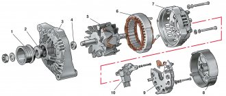
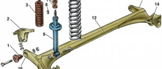
| ArcheologyArchitectureAstronomyAuditBiologyBotanyAccountingMilitaryGeneticsGeographyGeologyDesignArtHistoryCinemaCookingCultureLiteratureMathematicsMetallurgyMythologyMusicPsychologyReligionSportsConstructionTechnologyTransportTourismEstatePhysicsPhotographyChemistryEcologyElectricityE electronicsenergy | 4.1 Rear beam structure The rear suspension beam for cars of the VAZ 2110 family consists of two longitudinal arms 13 (Fig. 1) and a connector 12, which are welded together through amplifiers. In the rear part, brackets 14 with eyes for attaching shock absorbers are welded to the suspension arms, as well as flanges 15, to which the rear wheel axles are bolted together with the wheel brake shields. At the front, the suspension arms have welded bushings 16 into which rubber-metal hinges 1 are pressed. Bolts pass through the hinges connecting the suspension arms to stamped-welded brackets 2, which are attached to the side members of the car body VAZ 2110, VAZ 2111, VAZ 2112 with welded bolts. Springs 11 (see Fig. 1) of the suspension rest with one end on the shock absorber cup 9, with the other, through an insulating rubber gasket 10, in a support welded to the inner arch of the body of the VAZ 2110 family of cars. The rear suspension shock absorber of the VAZ 2110 family of cars is hydraulic, telescopic, double-sided actions. It is attached with bolt 9 (Fig. 2) to the trailing arm suspension bracket of the VAZ 2110 car. The upper shock absorber mounting is pin-type: the rod is attached to the upper support 5 of the suspension spring through rubber cushions 6 and support washer 3. The shock absorber parts are shown in Fig. 3. In hub 13 (see Fig. 2) there is a double-row angular contact bearing 12, similar to the front wheel hub bearing, but smaller in size. Unlike the front wheel hub, where the inner bearing ring is installed on the hub with guaranteed interference, bearing 12 on axle 14 has a transitional fit. Fig.1. Rear suspension parts: 1 – rubber-metal hinge; 2 – suspension arm mounting bracket; 3 – shock absorber casing; 4 – compression stroke buffer; 5 – casing cover; 6 – support washer; 7 – shock absorber cushion; 8 – spacer sleeve; 9 – shock absorber; 10 – insulating gasket; 11 – rear suspension spring; 12 – lever connector; 13 – lever of the rear suspension beam; 14 – shock absorber mounting bracket; 15 – flange; 16 – lever bushing | Rice. 2. Shock absorber mounting: 1 – protective casing; 2 – compression progress buffer; 3 – support washer; 4 – spring insulating gasket; 5 – upper support cup of the suspension spring; 6 – shock absorber rod mounting pads; 7 – lower spring support cup; 8 – shock absorber; 9 – shock absorber mounting bolt; 10 – wheel hub axle mounting bolt; 11 – brake drum; 12 – hub bearing; 13 – wheel hub; 14 – axis; 15 – nut; 16 – retaining ring; 17 – locating pin | Rice. 3. Rear suspension shock absorber parts: 1 – recoil valve nut; 2 – recoil valve spring; 3 – recoil valve plate; 4 – washer; 5 – recoil valve disc; 6 – throttle disk of the recoil valve; 7 – piston; 8 – piston ring; 9 – bypass valve plate; 10 – bypass valve spring; 11 – limit plate; 12 – spacer sleeve; 13 – reservoir; 14 – rod; 15 – compression buffer support; 16 – nut; 17 – oil seal cage; 18 – rod protective ring; 19 – oil seal; 20 – sealing ring of the tank; 21 – rod guide bushing; 22 – cylinder; 23 – compression valve cage; 24 – intake valve spring; 25 – compression valve plate; 26 – throttle disk of the compression valve; 27 - compression valve discs; 28 – compression valve body; 29 – rubber-metal hinge |
When replacing worn rubber-metal hinges of the rear suspension beam arms, special tools and skill are required, so it is recommended to replace the hinges in a specialized workshop.
| EXECUTION ORDER |
| 1. Remove the rear suspension shock absorbers on both sides of the car (see subsection 4.2.2). | |
| 2. Disconnect the parking brake cables from the equalizer, remove the shells of both cables from the bracket on the body, bend two brackets securing each cable to the body and remove both cables from the rear suspension beam mounting brackets, for easy access to the beam mounting bolt (see subsection 6.10 .3). | |
| 3. Disconnect the elastic arm of the pressure regulator drive from the bracket on the rear suspension beam (see subsection 6.4.1). | |
| 4. Disconnect one brake hose on both sides from the tubes on the rear suspension beam. Plug the hose holes. | |
| 5. Unscrew one nut on both sides of the bolts securing the beam to the brackets, knock out the bolts and remove the beam by rolling it out from under the car on wheels. | |
| Recommendation | |
The manufacturer recommends removing the beam together with the brackets by unscrewing three nuts securing them. However, after prolonged use, rusted studs may break. Therefore, it is better to remove the beam by disconnecting it from the brackets that remain on the body.
Finally tighten the nuts of the beam mounting bolts with the vehicle standing on the ground. After installation, bleed the brake system and adjust the parking brake. Download information from the page
What affects the cost?
Excluding such conventions as country of production, brand, type of packaging and warranty, it is worth considering the main pricing factors, namely:
- Lever connector thickness.
- Complete set (replacement of rubber silent blocks with polyurethane ones, stretching bolts with hardened ones).
- The size of the seat for the silent block (standard 48 mm, from LADA Priora 51 mm).
- Application of dependent reaction rods (transverse and longitudinal deformation stabilizers).
- Delivered with brake drums, linings and working cylinders.
- Implementation of internal mortgages for fastening the brake line.
The thickness of the beam refers to its central part, excluding the welded jibs and the rear stabilizing rod.