Perhaps someone will be interested!
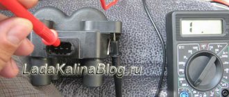
Somehow, I searched the entire network on the topic of pinout and design of the so-called individual coils 2112 and did not find anything intelligible, so I decided to buy one and find out everything myself - what is its pinout, is there a transistor inside and a diode at the output. I bought it for RUR 600, produced by Itelma (Russia). Bosch were sold for 800, but naturally, this is the same thing only of better quality.
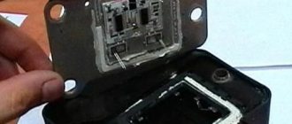
In general, what happens is that there is no transistor inside (and that’s good!), the connector is three-pin, the two outermost contacts go only to the primary, the middle contact is the “ground” of the secondary (ground), and is connected to the same middle contact (ground). and the coil screen is a metal “wrapper” on the coil body, but the “hot” high-voltage output of the secondary goes to the central electrode of the spark plug THROUGH A DIODE. Since these coils work in a TRANSISTOR ignition system, before the moment of spark formation, the coil core is magnetized, and spark formation occurs due to the “reverse” emission (self-induction) of the coil, so this vile diode guarantees the absence of a spark at the moment the core begins to magnetize, that is, before necessary.
Personally, I was interested in these coils as the basis for a mega-powerful, multi-spark but at the same time “non-noising” system. ignition, so the fact of the presence of a diode is extremely disappointing. It turns out that such coils cannot work in a MULTI-SPARK system, since they release only a “minus” relative to the mass onto the spark plug. Of course, there is a way out - simply drill out this nasty diode and put a “short one” in its place, or “break through it to hell.” In general, we will try)
By the way, there is another problem - the length of the coil installed on the spark plug from the top edge of its cutout to the spark plug gasket is already 200 mm! ! ! This will not fit everywhere) However, if, for example, you remove the diode, you can undoubtedly shorten it.
Schematic electrical diagrams, connecting devices and pinouts of connectors
Today we will look at the design and diagrams of ignition systems for VAZ cars of all major models. Since carburetor versions of VAZ are practically history, we will dwell in detail on the ignition systems of injection cars. Their ignition system is based on an electronic ignition module. We also recommend that you carefully consider the choice of spark plugs and the quality of high-voltage wires, because the quality of the spark and, accordingly, the operation of the ignition system as a whole will depend on them. The information is intended as a reference guide for self-repairing a car.
Pinout, connection diagram and check of the VAZ ignition coil
Today we will look at the design and diagrams of ignition systems for VAZ cars of all major models. Since carburetor versions of VAZ are practically history, we will dwell in detail on the ignition systems of injection cars. Their ignition system is based on an electronic ignition module. We also recommend that you carefully consider the choice of spark plugs and the quality of high-voltage wires, because the quality of the spark and, accordingly, the operation of the ignition system as a whole will depend on them. The information is intended as a reference guide for self-repairing a car.
Purpose and principle of operation
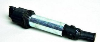
The ignition coil 407.3705 is an electromechanical device that generates the high voltage necessary to produce electrical sparks between the spark plug electrodes. Which serve to ignite the combustible mixture in the engine cylinders. In fact, this is a step-up transformer based on two windings, converting 12V automotive network into high voltage pulses, up to 35kV. They are installed on the valve cover of a car engine in the amount of four pieces.
When the ignition is turned on, the voltage from the on-board network supplied to the input of the ignition coil enters the primary winding. As a result, a magnetic field is formed. Under the influence of an electromotive force, which is proportional to the number of turns in the circuit, the secondary winding generates high-voltage pulses that are supplied to the spark plug. On the spark plug, under the influence of these pulses, a spark is formed between the electrodes. The spark ignites the compressed fuel-air mixture in the engine cylinder. The coil transmits high voltage to the spark plug, which, in turn, ignites the combustible mixture.
General view of the individual ignition coil 407.3705:
Pinout and diagram of the VAZ ignition coil
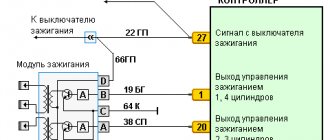
Pinout of ignition coil modules for various car models of the VAZ family:
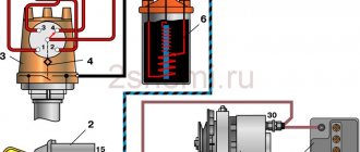
Ignition VAZ 2101
1 – generator; 2 – ignition switch; 3 – ignition distributor; 4 – breaker cam; 5 – spark plugs; 6 – ignition coil; 7 – battery.
Ignition VAZ 2106
1 – ignition switch; 2 – fuse and relay block; 3 – EPHH control unit; 4 – generator; 5 – solenoid valve; 6 – microswitch; 7 – spark plugs; 8 – ignition distributor; 9 – ignition coil; 10 – battery.
Ignition VAZ 2108, 2109
Ignition VAZ 2110
Ignition VAZ 2111
Ignition VAZ 2112
Ignition VAZ 2114
Diagram of a non-contact ignition system: 1 – non-contact sensor; 2 – ignition distributor sensor; 3 – spark plugs; 4 – switch; 5 – ignition coil; 6 – mounting block; 7 – ignition relay; 8 – ignition switch.
How to check the ignition coil of a VAZ
If the ignition coil is faulty, the engine will not start. A characteristic sign of a faulty coil is its increased temperature when the ignition is turned off. This is easy to determine by touch.
Signs of a faulty ignition module may include the following:
- hesitant engine starting or failure to start;
- failures during sudden changes in speed;
- high fuel consumption;
- two cylinders do not work, the engine is feverish;
- lack of dynamics;
- a sharp drop in power;
- drop in power and thrust after warming up.
These symptoms may not only be caused by the ignition module. To determine the malfunction, it is enough to spend a few minutes diagnosing spark plugs, high-voltage wires and caps. This will eliminate the remaining elements of the ignition system and make sure that it is the ignition module that is faulty.
Checking the ignition coil is performed in one of 2 ways. The simplest one is to remove the central wire from the breaker-distributor, bring it to the motor housing and turn it with the starter, and a running spark should appear. After this, we check the energy supply to a separate spark plug, for which we unscrew the working spark plug, bring its contact to ground and attempt to start the engine. In this case, the spark should come from the wire to ground. If it is absent, the reason will be a malfunction of a system element such as the ignition coil.
To check the module in the second way, we only need a multimeter, then follow the step-by-step instructions:
- We check the power supply and the presence of pulses supplied from the ECU. We check the power between the central terminal (15) of the wire block connected to the module and the engine ground. When the ignition is on, the voltage should not be less than 12 V. Otherwise, either the battery is dead or the ECU does not work.
- We check the pulses from the ECU on the wiring block. We install one tester probe on connector 15, the second on the far right, then on the far left. The assistant cranks the engine with the starter, and at this time we record short-term voltage surges with a tester. If there are no impulses from the ECU, it is he who is to blame.
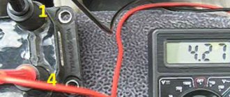
- We check the resistance on the secondary windings of the coils. We put the tester in resistance measurement mode and measure it at the high-voltage terminals of the module cover. Between pins 1 and 4 and pins 2-3, the resistance should be 5.4 kOhm. Otherwise, the module must be replaced.
- We check the resistance of the primary windings between contacts 15 and the rightmost, then the leftmost terminals. Nominal - 0.5 Ohm. Deviation is not allowed.
- Check the module for a short circuit. In ohmmeter mode, install one multimeter probe on the central terminal, the second on the metal body. There shouldn't be any resistance. If the device detects at least some resistance (other than unity or infinity), the module must be replaced.
How are ignition wires different from regular ones?
ATTENTION! A completely simple way to reduce fuel consumption has been found! Don't believe me? An auto mechanic with 15 years of experience also didn’t believe it until he tried it. And now he saves 35,000 rubles a year on gasoline!
So, the ignition system wires are otherwise called high-voltage or armored wires. This is an essential part of the system through which electrical impulses are transmitted. At the moment when voltage is applied to the spark plugs, the combustible mixture (FA) ignites. Thanks to this, a new cycle of operation of the internal combustion engine begins.
The design of armored wires, in contrast to conventional ones, differs markedly. So, in addition to the copper core, which is responsible for conducting current and protection (insulation), they also contain tips and plastic caps.
What are metal tips and protective caps for? The former successfully perform the functions of contacts, the latter protect the wires from dirt and dust. In addition, the armored wire ends are manufactured to fit precisely into the spark plug sockets and into the holes on the distributor.
Important point. The resource and service life of the armored wires as a whole depends on how well the tips are made.
When choosing between one or another armored wire model, you should keep two important points in mind. The first is resistance, and the second is their breakdown voltage. The relatively better transmission of electrical impulses is, of course, associated with a low resistance value. As for the second value, it directly affects the resistance to electrical breakdowns and short circuits.
The table below shows various resistance values of armored wiring from manufacturers Tesla, Caesar, Elephant and others. Of course, Tesla has received the most approval from car owners around the world. And along with good resistance, they are also distinguished by excellent breakdown voltage.
The price for a set of Tesla armored wiring does not, as a rule, exceed 500-600 rubles.
| Manufacturer | Resistance on cylinder No. 1 (kOhm) | Resistance on cylinder No. 2 | Resistance on cylinder No. 3 | Resistance on cylinder No. 4 | Breakdown voltage (kV) |
| Tesla | 3..27 | 4..16 | 5..02 | 6..26 | 50 |
| Cezar | 3..1 | 3..53 | 4..23 | 5..34 | 50 |
| Finwhale | 1..95 | 2..18 | 2..6 | 3..42 | 50 |
| Ween | 6..17 | 6..57 | 7..52 | 9..89 | 35 |
| Slon | 4..24 | 4..74 | 5..19 | 7..6 | 50 |
Connecting and replacing VAZ short circuit
The procedure for removing and installing the ignition coil on old VAZ models:
- First, disconnect the central high-voltage wire leading to the distributor (ignition distributor).
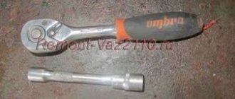
- Disconnect all power wires from the coil contacts. Since they are fastened with nuts, you will need an 8 wrench for this.
- If you don’t know which wires to connect to which connector later, it’s better to immediately remember or mark them somehow, so that later during installation you can connect them correctly.
- Unscrew the coil housing. It is attached to a clamp (clamp), which is pressed to the car body with two nuts.
- After the work has been done, you can remove the ignition coil and replace it if necessary.
For new type VAZ cars:
- We remove the “minus terminal” from the battery.
- Remove the top protective cover of the engine. If the engine volume is 1.5 liters, then this part is missing and this step is skipped.
- We remove the high-voltage wires from the coil.
- Now, using a 13mm wrench, unscrew the two fasteners.
- Using a 17mm wrench, loosen one bolt securing the coil.
- We take out the module.
- Use a hexagon to unscrew the coil from the holder.
- Assembly is carried out in reverse order.
Particular attention should be paid to the connection, since high-voltage wires must be located in the strict order provided for by the design. If this is not done, the car will stall or the engine may not start at all.
Replacing the ignition coil on a VAZ is quite simple. Even a novice motorist can do this in his garage, and if everything seems too complicated, contact a car service center. Particular attention should be paid to the choice of product, since this will determine how well the engine and ignition system will work.
Repair
So, for the VAZ 2110 the most common problem is the disappearance of voltage on cylinders 2 and 3. After some time, the engine starts working normally again if you press the rear plate of the module.
You should not put up with such a situation; it is better to immediately check the functionality of the unit, restore or replace it completely.
Removing the module
The procedure is quite simple.
- Disconnect the negative cable from the battery.
- Remove the plastic cover that covers the motor.
- Remove the wires from the spark plugs.
- Disconnect the wires from the ignition module. Their numbering is indicated on special white rings. And the cylinder number is indicated on the ignition module housing.
- Disconnect the connector from the ignition module.
- Using a 10mm socket, unscrew the three nuts that hold the block we are looking for.
- Carefully remove it, after which you can begin further work.
Now let's move directly to working with the module:
- Open the aluminum plate on the ignition module. A flathead screwdriver is useful for this.
- Inside you will find a small printed circuit board with electronic components. It is covered with a transparent layer of silicone, which will have to be removed.
- There are also wires that connect the board to the connector contacts. They are made of aluminum, so they can tear quickly.
- Tear off all the wires from the contacts, don’t be afraid. Others will be installed in their place. By the way, experts recommend using stranded wires used in computer mice.
- The ignition module circuit includes two switches and two powerful transresistors. If you decide to change these elements, you need to know that the switches are manufactured by SGS-THOMSON (model L497D1), and the transistors are of the BU931 type.
- The contacts are made of aluminum, so you will need a special flux to work with this metal.
- We solder the wiring to the board. It is more difficult to solder to the transistor collectors, since they are covered with a special material, the soldering of which is problematic. Therefore, try to hide the top coating from the element as carefully as possible. To prevent the soldering iron from transferring all the heat to the plate, place it on the stove and heat it to 180 degrees Celsius.
- Solder the wires to the contacts on the module so that they are as short as possible.
- Cover the areas where you soldered with varnish. Regular nail polish borrowed from your wife will do.
- Check if the ignition module is working.
- If everything is fine, coat the inner surface with a special autosealant, then reassemble in the reverse order.
- Upon completion of assembly, the wiring should be positioned fairly freely. Make sure that they are not compressed inside the box and that the integrity of the connections is not broken.
Carrying out a similar repair of the ignition module on a VAZ 2110 with your own hands will not be difficult.
But be careful, act carefully and consistently
Pay special attention to the soldering process
But keep in mind that we have addressed the problem of bad contacts. She is not the only one for the “ten”. You may need to pinout the ignition module on the VAZ 2110. For this, it is better to contact specialists.
If the cause of the malfunction lies elsewhere, then there is a high probability that it is better to simply replace the VAZ 2110 8-valve ignition module with a new one. The search may drag on without yielding results. Replacing the element will completely solve the current problem.
Possible causes of failure
The weak point of the ignition coils and modules is the secondary winding, which generates a high voltage pulse. A coil break or breakdown may occur in it. The following factors lead to this phenomenon:
- use of low-quality or unsuitable candles;
- operation with non-functioning high voltage wires;
- frequent attempts to check the spark.
The high-voltage pulse arising in the secondary winding must be realized (spent). If this does not happen (if the integrity of a high voltage wire is broken, for example), a high-energy electrical pulse seeks an outlet. He will find it, with a high degree of probability, in the thin secondary winding.
Often, a module malfunction occurs when the integrity of poor-quality factory soldering of wires going to the switch elements is violated. This happens from vibration. Also, the cause of non-working coils can be a banal contact failure in the incoming connector. Another factor leading to a malfunction of the ignition unit is often moisture that gets on the device during washing or driving in unusual conditions.
We check the ignition module on the injection VAZ-2110 8 valves with our own hands
At different times, different engines were installed on the VAZ-2110 car, both carburetor and injection. However, regardless of the type of power system and the number of valves (8 or 16), all engines are assembled on the unit base of the old engine 21083 and 21093. The most progressive of these engines is the 16-valve 1.6-liter VAZ 21124 engine with a power of 89 horsepower. Today we will touch on the ignition module for 8-valve engines 2111 and 21114 (1.6 l), check its performance and find a suitable replacement for the failed module.
Version of the module on the 8-valve VAZ-2110
The top ten was equipped with two 8-valve engines of different sizes - 1.5 (2111) and 1.6 liters (21114). The ignition modules for these engines are different.
- The one and a half liter engine has a module with article number 2112-3705010,
- and the 1600 cc engine is equipped with module 2111-3705010.
A module for a 1.5 liter engine costs about 1500-2100, and the second one is 500 rubles cheaper.
Which is better?
SOATE devices manufactured in Stary Oskol have proven themselves to be the most reliable ignition modules.
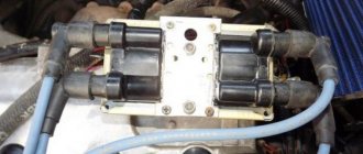
Module structure
The module consists of two ignition coils and two high-voltage switch switches.
The coil generates a high voltage pulse, and it is a simple transformer with two windings, primary (induction voltage about 500 V) and secondary (induction voltage at least 20 kV). All this is assembled in a single housing, on which there is a connector for signal wires (from the engine control unit) and four terminals for high-voltage wires.
The module operates on the principle of an idle spark - it distributes sparks in pairs to cylinders 1-4 and 2-3 according to impulses transmitted from the ECU.
Module design
Before you begin repairing the ignition module, it is worth understanding what it consists of. So, let's look at the design of this element:
- Two ignition coils generate a high voltage pulse.
- Dual channel switch.
If there are problems with the operation of the ignition module, there are reasons for this. It is worth warning that with this malfunction the “Check Engine” lamp does not light up: engine stops, loss of spark, interruptions in the operation of the power unit, etc.
Diagnosis and repair require basic knowledge not only of conventional electrical installation, but also of the principles of automotive electrical installation. In addition, the process will require skills in using a digital multimeter to be successful.
Repair process
Often the high-voltage pulse is lost in cylinders 2 and 3. So, in order to begin repairing the ignition module, of course, you will have to disassemble it. To do this, disconnect the high-voltage cables and unscrew the assembly itself from the supports. When the preparatory operations are completed, you can proceed directly to the repair process:
- We tear off the aluminum plate.
Open the aluminum plate with a screwdriver
Wire welding diagram and arrangement of elements on the boards
Diagram of the assembled ignition module
Fully assembled ignition module
Video about repairing the ignition module on a VAZ-2112
The video will tell you about repairing the ignition module and how to remove it from the car.
Signs
- If one of the module coils completely fails, then two cylinders do not work. This is clearly visible even to the naked eye - the engine is feverish at idle, starting is difficult, fuel consumption is sky-high, loss of dynamics.
- To eliminate all other components of the ignition system, make sure that the spark plugs are in working order. To do this, unscrew them and check the spark on each of the spark plugs by cranking the engine with the starter and placing the spark plug with the high-voltage wire on the head so that the body (threaded part) of the spark plug touches the engine mass. If there is no spark or it is weak, replace the spark plug with one that is known to work.
- If this does not lead to anything, check the high-voltage wires. Thus, we will exclude spark plugs, caps and high-voltage wires from the list of non-working elements. Next we will check the ignition module.
Spark plug
The VAZ-2101 used Soviet spark plugs of the A17DV brand, but now, when the market is filled with high-quality foreign-made brands, you can easily choose spark plugs with much better characteristics, the main thing is not to fall for a Chinese counterfeit.
Design features of candles
The length of the threaded part of the spark plug is 19 mm, with a pitch of 1.25. The hexagonal part (for the spark plug wrench) is made with a size of 20.8 mm.
The permissible gap between the spark plug electrodes is checked with a probe. According to the book, with a contact system, the gap of the VAZ 2101 spark plug should correspond to 0.5 - 0.6 mm.
How to check the ignition module?
- First of all, we carefully inspect the module body. There should be no chips, burns or cracks on its surface. A module with a damaged casing is replaced without any hassle.
- If the spark is unstable only on cylinders 1-4 or 2-3, one of the module coils is probably damaged. In any case, we will conduct a comprehensive check of the device. For this we will need a regular multimeter.
Repair
The design of the ignition module is quite complex: it includes one or more coils, a board, contacts and wires. Of all the above elements, only contact connections can be repaired; in some cases, replacement of parts (transistors, coils) is possible.
The module is dismantled and opened for repair purposes. For this you will need:
- Socket wrenches with heads 1, 13 and 17.
- Hexagon 5.
- Screwdriver.
- Soldering iron.
- Flux for aluminum.
- Stranded wire.
- Nail polish.
Repair of the ignition module is carried out in the following order:
- On the removed device, open the case by prying it off with a screwdriver.
- Remove the silicone film covering the board.
- All aluminum is removed from the explosive contacts.
- On the board, new wires are soldered in place of all the dismantled old ones. To do this, the surface of the collector is cleaned of deposits, after which the board is heated to 180°C (a characteristic smell will indicate when the desired temperature has been reached). During the soldering process, the ends of the wires are connected to the module.
- At the end of the operation, all contacts, the board and the module are covered with nail polish.
- The device is assembled in the reverse order, installed on the car and the engine is started. In case of normal operation, the ignition module is sealed tightly with sealant, while the wires are tucked inside the cavity so that they are not pinched at the edges by the plate.
If the device does not work, then a breakdown inside the module should be looked for more carefully. The transistor, electronic component may have failed, or there may be a break in the coil. Such a repair makes sense only if its price is significantly lower than the cost of a new part.
Diagnostic procedure
The diagnostic procedure can be as follows:
- Disconnect the connector with signal wires from the module.
- Turn on the ignition and check the voltage at terminal 15 (central) of the control wire block. The rated voltage is 12 V. A drop or absence of voltage when the battery is charged indicates that the engine control unit does not supply power to the module. This means the reason lies in the ECU.
- We check the resistance of the primary windings of the coils - put the multimeter in resistance measurement mode and take readings from the rightmost and central terminals, then from the leftmost and central terminals. The nominal resistance of the primary windings is approximately 0.5 Ohm.
We measure the resistance of the secondary windings between terminals 1-4 and 2-3 high-voltage wires. Nominal value: 5.4 kOhm. If the readings do not correspond to the nominal value, the coil is not working correctly.
Check the module for a short circuit. To do this, install one tester probe on the central pin 15, the second on the metal body. The device should show the absence of a short circuit (one or infinity). Otherwise, one of the coils has shorted to the housing.
Errors
A module malfunction can also be determined using an error scanner. Error codes associated with the module are:
- R-3000, R-3001, R-3002, R-3003 and R-3004 - gaps in sparking, the module itself, spark plugs, high-voltage wires or the ECU may be to blame;
- R-0351 - the coil of cylinders 1-4 does not work;
- R-0352 - the coil of 2-3 cylinders does not work.
The scanner readings do not yet indicate problems with the module itself.
It is possible that the spark plugs are not working or the high-voltage wires are broken, but if we initially diagnosed them, then the fault lies entirely with the ignition module. In this case, we can repair it ourselves, or buy a new one, which is faster, easier and guarantees uninterrupted operation of the ignition system. Good luck to everyone, strong spark and good roads!