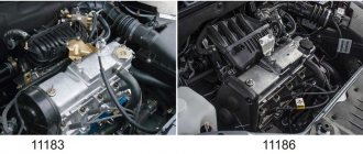
November 10, 2020 Lada.Online 18 085 0
To control the tightening torques of threaded connections of the engine, gearbox and other components of the Chevrolet Niva 2123, it is allowed to use torque and pointer wrenches from manufacturers that have certificates of conformity and type approval of measuring instruments in the Russian Federation. The tightening torques of threaded connections that must be controlled during assembly are given below.
Because all dynamo keys have an error. It is better to take the moment in the middle of the range. Minimum permissible - maximum tightening torque. For example: 100-110 Nm.
Engine
- Bolt for fastening the main bearing caps М10×1.25 68.31-84.38(6.97-8.61)*
- Oil pump mounting bolt MB 5.10-8.20 (0.52-0.85)
- Breather cover mounting stud M8 12.7-20.6(1.3-2.1)
- Breather cover mounting nut M8 12.7-20.6(1.3-2.1)
- Cylinder head bolt M8 31.36-39.10(3.20-3.99)
- Nut of the stud securing the inlet and outlet pipelines M8 20.87-25.77 (2.13-2.63)
- Connecting rod cover bolt nut M9x1 43.32-53.51 (4.42-5.46)
- Flywheel mounting bolt N110x1.25 60.96-87.42 (6.22-8.92)
- Chain tensioner shoe mounting bolt M10×1.25 41.2-51.0 (4.2-5.2)
- Bolt for fastening the head cover of the cylinder block MB 1.96-4.60 (0.20-0.47)
- Oil pump drive shaft sprocket mounting bolt М10×1.25 41.2-51.0(4.2-5.2)
- Camshaft sprocket mounting bolt М10×1.25 41.2-51.0(4.2-5.2)
- Spark plug M14x1.25 30.67-39.00 (3.13-3.99)
- Coolant pump mounting bolt M8 21.66-26.75(2.21-2.73)
- Nut for fastening the outlet pipe of the cooling jacket M8 15.97-22.64 (1.63-2.31)
- Crankshaft ratchet M20x1.5 101.30-125.64 (10.34-12.80)
- Generator bracket bolt M10×1.25 44.1-64.7(4.5-6.6)
- Generator bar mounting nut M10×1.25 28.03-45.27 (2.86-4.62)
- Nut of the bolt securing the generator to the bracket M12×1.25 58.3-72.0 (5.95-7.35)
- Nut securing the mounting bar to the generator M10×1.25 28.03-45.27 (2.86-4.62)
- Nut for fastening the front engine mount bracket M8 10.4-24.2(1.1-2.5)
- Nut securing the front support cushion to the cross member bracket M10×1.25 27.4-34.0 (2.80-3.46)
- Nut for fastening the cross member of the rear engine mount M8 15.0-18.6 (1.53-1.90)
- Nut securing the rear engine mount to the gearbox M8 28.3-28.8 (2.38-2.94)
- Nut securing the rear engine mount to the cross member M8 15.9-25.7 (1.62-2.62)
Cylinder head (cylinder head) bolt. M12×1.25:
1st step - tighten bolts 1–10 to a torque of 20 Nm; 2nd step - tighten bolts 1–10 to a torque of 70–86 Nm, and bolt 11 to a torque of 31–39 Nm. 3rd step - then turn bolts 1–10 by 90°; 4th move - and another 90°;
Camshaft bearing housing stud nut M8 18.33-22.64(1.87-2.30)
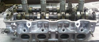
Torque and sequence of tightening the camshaft bed
Camshaft cover tightening sequence
Correct tightening of the camshaft bed, as well as other parts of the cylinder head, determines the normal functioning of all components and assemblies. So, in order to tighten threaded connections, a standard tightening pattern and a torque wrench are used.
Before installing the bolts in place, they must be washed thoroughly and lubricated with silicone grease.
In order to properly tighten the bolts, you need to know the sequence. It starts from the middle part and gradually moves directly to the edges. The detailed sequence can be seen in the photo below.
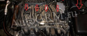
Tightening diagram for each camshaft bed bolt with numbering
As for the tightening force itself, it is 8.0-10.0 Nm . After the bed is installed on the block head, the connection bolts are tightened by hand or without much force using a ratchet with a head.
We tighten all the bolts by hand, but do not tighten them
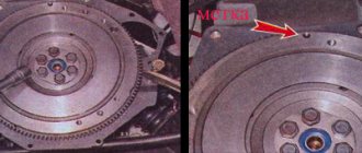
When all the bolts are in place, you need to take a torque wrench and tighten them according to the standards in the order indicated above.
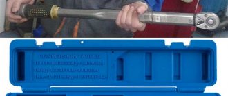
Torque wrench for tightening threaded connections
In what cases is it necessary to tighten the camshaft bed?
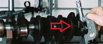
The bolts are tightened. Marked with arrows
Tightening the camshaft bed will be necessary if it was previously dismantled for restoration and repair work. So, in what cases will you need to remove the bed, let’s look at it in more detail:
- Replacing camshafts, lifters or valve seals.
- Overhaul of the block head.
- Engine repair operations.
- Replacement of individual elements of the cylinder head.
Consequences of improper bed tightening
The consequences of improperly tightening the camshaft bed include the following:
- Oil leakage due to a gap or loose connection.
- Passing air inside the cylinder head.
- Malfunction of the engine or cylinder head.
- Ingress of foreign objects (water, dirt, dust).
All these factors can negatively affect the performance of the cylinder head and main power unit.
Transmission
- Reversing light switch M14x1.5 28.4-45.1 (2.9-4.6)
- Bolt securing the clutch housing to the engine M12×1.25 53.9-87.2 (5.5-8.9)
- Nut securing the clutch housing to the gearbox M10×1.25 31.8-51.4 (3.25-5.25)
- Nut securing the clutch housing to the gearbox M8 15.7-25.5(1.6-2.6)
- Rod clamp cover bolt M8 15.7-25.5(1.6-2.6)
- Rear cover mounting nut M8 15.7-25.5(1.6-2.6)
- Nut of the rear end of the secondary shaft M20x1.0 66.6-82.3 (6.8-8.4)
- Intermediate shaft bearing clamping washer bolt M12×1.25 79.4-98.0 (8.1-10.0)
- Bolt securing the fork to the gearshift rod MB 11.7-18.6(1.2-1.9)
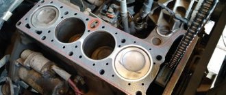
Installing piston rings
Now you need to install the piston rings on the piston. As a rule, three rings are installed on one piston. The upper and middle compression and lower oil rings are removable. The rings have an engraving, the inscription should be facing up,
if it is not there, then you can navigate by the chamfer, which is located either along the inner or outer diameter of the piston rings. This chamfer acts as a stiffening rib, which creates resistance to the loads that arise when gases expand in the combustion chamber. If there is a chamfer along the inner diameter, then the ring is placed with the chamfer up, if along the outer diameter, then with the chamfer down. The oil slip rings also have an engraving that should face up; if it is not there, then the direction of the ring does not matter.
The rings on the pistons must be placed in such a way that the ring connectors are not located under each other and do not fall into the groove under the pin. Since, for example, the middle ring connector is located on one side of the piston, the upper and lower ring connectors must be on the other side of the piston, and must be spaced apart from each other, but not fall into the piston pin recess
Transfer case
- Nut securing the suspension bracket to the pillow axis M10×1.25 26.5-32.3 (2.7-3.3)
- Nut securing the suspension bracket to the body M8 15.0-18.6(1.53-1.90)
- Nut securing transfer case housing covers, front axle drive housing, speedometer drive housing, control lever bracket M8 14.7-24.5(1.5-2.5)
- Differential lock switch M16×1.5 28.4-45.0 (2.9-4.6) Bolt securing the forks to the gear shift rods MB 11.8-18.6 (1.2-1.9)
- Bolt securing the forks to the differential lock rod M12×1.25 11.7-18.6(1.2-1.9)
- Nut securing the propeller shaft flange to the drive shaft and to the drive shafts of the front and rear axles M16×1.5 96.0-117.6(9.8-12.0)
- Driven gear mounting bolt М10×1.25 66.6-82.3 (6.8-8.4)
- Nut for securing the rear bearing of the drive shaft and the rear bearing of the intermediate shaft M18×1.5 96.0-117.6(9.8-12.0)
Signs of Camshaft Wear
The operation of the camshaft is associated with constant exposure to high loads, as a result of which the part gradually wears out and requires replacement. The need for repair arises when characteristic symptoms appear:
- knocking when the engine is running under load;
- reduction in power indicators.
There are a number of reasons why the RV fails:
- natural wear and tear;
- low-quality motor oil;
- low oil pressure in the lubrication system;
- insufficient oil level or so-called oil starvation;
- engine operation at high temperatures, which leads to deterioration of the lubricant properties;
- mechanical damage (wear or broken chain).
The main malfunctions that impair the performance of the camshaft are scuffing on the working surfaces (journals and cams) and deterioration of the limiter.
Over time, the camshaft's cams and journals wear out.
Knock
It is quite problematic to determine from the sounds coming from the engine compartment that the problem is related specifically to the camshaft, but it is still possible. The knocking sound of the engine resembles the dull blows of a hammer, which become more frequent as the engine speed increases. However, the best way to diagnose a shaft is to dismantle, disassemble and troubleshoot it. During inspection, the shaft should not move in the housing relative to the axis, otherwise a dull sound will be produced when hitting the limiter.
Video: reasons for the longitudinal play of the VAZ camshaft
Power reduction
The drop in power on classic Zhiguli cars is a phenomenon caused by wear of the camshaft and rockers. With proper engine operation (timely oil changes, monitoring its level and pressure), the problem only appears over long vehicle runs. When the cams wear out, the required phase width and valve lift at the intake are no longer ensured.
When the shaft and rockers wear out, the motor power may decrease several times
Deformation
The RV can become deformed under extreme heat, which is caused by problems in the cooling and lubrication systems. At first, the problem may manifest itself as a knocking sound. Therefore, if there is a suspicion of this breakdown, for example, the motor has overheated, then it is recommended to diagnose the shaft in order to avoid more serious troubles with the engine timing belt.
Front suspension
- Nut of the lower bolts securing the cross member to the body side members M 12×1.25 66.6-82.3 (6.8-8.4)
- Nut of the upper bolts securing the cross member to the body side members M 12×1.25 66.6-82.3 (6.8-8.4)
- Nut of the bolt securing the rebound buffer bracket to the cross member M8 15.1-18.6 (1.53-1.90)
- Nut of the upper arm axle mounting bolt M 12×1.25 66.6-82.3 (6.8-8.4)
- Nut securing the upper end of the shock absorber M10×1.25 27.4-34.0 (2.80-3.46)
- Nut securing the lower end of the shock absorber M10×1.25 50.0-61.7 (5.1-6.3)
- Front wheel hub bearing nut M 18×1.5 cm, “Chassis”, p. 169
- Bolt securing the caliper to the steering knuckle M10×1.25 29.1-36.0 (2.97-3.67)
- Anti-roll bar mounting nut M8 15.0-18.6(1.53-1.90)
- Nut securing ball pins to steering knuckle M 14×1.5 83.3-102.9 (8.5-10.5)
- Nut for fastening the brace to the suspension cross member M 12×1.25 66.6-82.3 (6.8-8.4)
- Nut for fastening the extension to the body M 16×1.5 104.9-169.5 (10.7-17.3)
- Nut connecting the lower arm axis to the cross member M 16×1.5 114.7-185.2(11.7-18.9)
- Nut for fastening ball joints to suspension arms M8 20.60-25.75 (2.10-2.63)
- Wheel bolt nut M 12×1.25 62.4-77.1 (6.37-7.87)
- Upper suspension arm axle nut M 14×1.5 63.7-102.9 (6.5-10.5)
- Nut of bolts securing the swing arm M 12×1.25 66.6-82.3 (6.8-8.4)
Approximate cost of replacement at a car service center
As you can see, replacing the camshaft is done with your own hands, in a home garage. You don't need any special equipment. On the other hand, this is an intervention in the engine design, which, if unsuccessful, can damage the power unit. One of the signs of malfunction is that after replacing the camshaft, the engine begins to trip. Therefore, in order to avoid major repairs and large expenses, many car owners trust the procedure to car services.
The price of replacing a camshaft starts at approximately 4,000 rubles. If you only need to replace the oil seal, the service station will charge the same amount. Replacing the shaft sensor costs 500 rubles. Replacing the timing chain of a passenger car equipped with a 4-cylinder engine is usually estimated at 6-7 thousand rubles. On SUVs and crossovers, this procedure costs more - 10-11 thousand rubles.
The camshaft is most often installed in the upper part of the cylinder head, but there are also systems with a lower location. The latter option is found mainly on old cars or cars with weak engines. The upper location of the element, on the contrary, is the calling card of powerful internal combustion engines with high operating speeds.
Steering
- Steering housing mounting bolt nut M10×1.25 33.3-41.2 (3.4-4.2)
- Nut of the pendulum arm bracket mounting bolt M10×1.25 33.3-41.2 (3.4-4.2)
- Ball pin nut for steering linkages** M 14×1.5 42.1-53.0 (4.3-5.4)
- Nut securing the steering shaft bracket and ignition switch M8 15.0-18.6 (1.53-1.90)
- Steering wheel nut M 16×1.5 31.4-51.0 (3.2-5.2)
- Bipod fastening nut M20x1.5 199.9-247.0 (20.4-25.2)
- Pendulum arm axis nut M 14×1.5 63.7-102.9 (6.5-10.5)
Camshaft replacement tools
The presence of these tools will simplify the procedure:
- a set of wrenches and sockets, including a ratchet;
- a set of screwdrivers - a slotted screwdriver for working with the seal or tweezers is required;
- micrometer;
- knob for clamping and rotation;
- dynamometer - a wrench for tightening threaded connections with a precisely specified torque;
- mount;
- puller and mandrel for pressing;
- hammer.
Before replacement, be sure to prepare a repair kit, which includes, in addition to the product itself: liners, oil seal, fastening bolts. If the system has hydraulic compensators, then these parts also need to be replaced.
Installing the clutch disc and basket
We install the clutch disc and basket on the flywheel. The clutch disc must be centered in relation to the internal bearing of the shaft cranks using a special shaft. On which there are two surfaces, one corresponds to the inner diameter of the bearing, the other corresponds to the inner diameter of the splined part of the clutch disc. The clutch disc is located with its protruding part towards the basket. After centering, install and tighten the clutch basket.
Installing the back cover
and the rear one after changing the seals in them.
Installing the oil pick-up
We install an oil intake and an emergency oil level sensor.
How to set the Timing Belt on a VAZ 2109 ~ AUTOINTERLINE.RU
Belt failure and installation procedure for VAZ 2109
Everyone needs to know how to set the operating time of a VAZ 2109, because no one is immune from the tape breaking. Fortunately, you are indescribable if you become the owner of a car with a 1.5 liter 8-valve engine. On them, when the belt is broken, the valves remain undamaged, but on the rest, unfortunately, the cylinder head must be repaired.
THIS IS INTERESTING: Audi A4 automatic transmission repair
How to determine if a timing belt is broken? Simply, because the spark disappears, the engine does not start and the crankshaft rotates faster than usual. Of course, you need to know how to correctly set the operating time of the VAZ 2109 when you replace the belt. Now let's consider this case.
How to remove the VAZ 2109 timing belt?
Before starting work, place chocks under the rear wheels and apply the handbrake. This will prevent the car from rolling away. Loosen the bolts on the right front wheel as it will need to be removed.
Lift the right side of the socket and finally remove the wheel (throw it under the engine crankcase so that if you fall, the car will not fall onto the brake disc). Open the hood and use a 10-key to remove the three bolts securing the camshaft guard. That's it, now you have a general idea about it, you can continue.
Now loosen the nut on the alternator and remove the drive belt. This will interfere with the replacement since you need to remove the pulley from the crankshaft. 19 key (you can even use a balloon), unscrew the bolt that screws the pulley to the crankshaft.
On carburetor versions of cars, you can insert a screwdriver into the groove of the pulley or a small key so as not to rotate the crankshaft. On the injector, you will have to use the help of a partner who will sit in the cabin and press the brake pedal (while you need to engage fifth speed).
When unscrewing the bolt, it is necessary to loosen the VAZ 2109 tension roller to facilitate belt removal. To do this, take a key up to 17 and unscrew the nut. And you can completely remove the VAZ 2109 timing belt, because when installing a new belt, it should also be replaced.
Remove the belt from the pulleys and pay attention to the condition of the pump. it should not have any gaps, pull its pulley to the sides
A characteristic feature of the presence of play and strong development of the liquid pump may be the appearance of development along the edge of the belt. If there is one, you should replace the pump immediately.
How to get to the camshaft?
To get to the VAZ 2109 camshaft, you will need to dismantle several parts. Arm yourself with the following tools:
- hexagon;
- wrench 13 or similar with a socket head;
- replaceable head for 10;
- ratchet handle.
To start work, turn off the power to your “nine” by disconnecting the battery. Then you need to set the piston of the first cylinder to the top dead center position.
Now we dismantle the devices that will interfere with the work in the following order:
- Air filter.
- Gasoline pump.
- Distributor.
- Let's take care of the gear. Remove the timing belt from it and assess its condition. Installation of a split gear will only be necessary if the old one has visual defects: chips, damage, deformation. If everything is in order, simply remove it by unscrewing the fastener. Don't forget to pick up the key so you don't lose it.
- Remove the drive housing on which the distributor is located.
- Now the path to the camshaft housing is clear.
- Remove all body fasteners, there are 10 of them in total.
- Next, pull out the fastening studs. Once all the pins have been removed, the housing can be removed.
- And here is the camshaft. Now he can be taken out of bed and examined.
The VAZ 2109 camshaft will need to be replaced if it is bent or the cams are damaged. A new one will cost about 1000 rubles. The camshaft is installed in the reverse order. Follow the order of tightening the bolts on the body so that part of the assembly is assembled normally and all parts take their position. More specific information on how to tighten can be found in your vehicle's owner's manual.