Code P0131 - Oxygen Sensor (Bank 1, Sensor 1) Circuit Low Voltage. Front O2 Sensor Circuit Low Voltage (Bank 1 Sensor 1).
The front oxygen sensor (Sensor 1) measures the amount of oxygen in the exhaust before the catalytic converter. The engine control unit (ECU) supplies a reference voltage to the oxygen sensor (OS). The sensor sends a signal voltage back to the ECU.
Low voltage means a lean air-fuel mixture—too much oxygen and too little fuel. High voltage means rich air/fuel mixture.
Code P0131 is set when the signal voltage from the front O2 sensor remains low. Modern cars use an air-fuel ratio sensor (A/F sensor) instead of an AC sensor, but it is also often called a front oxygen sensor. Bank 1 is the bank containing cylinder number 1. In a 4-cylinder engine, there is only bank 1.
Read more: What is bank 1, bank 2, sensor 1, sensor 2?
What does P0131 mean?
Trouble code P0131 indicates a problem with the oxygen sensor 1 (bank 1), also called the air fuel ratio sensor or heated oxygen sensor. This error indicates that the engine control module (ECM) has detected too low or incorrect voltage in the oxygen sensor circuit or an incorrect air-fuel ratio.
“Bank 1” refers to the left side of the engine, and “sensor 1” means that said sensor is located in the exhaust pipe before the catalytic converter.
VAZ errors and their solutions
Owners of domestic cars can easily find a problem with their car. This became possible thanks to the use of on-board computers and the introduction of modern equipment diagnostic tools. This article will describe in detail the errors and how to eliminate them in VAZ 2110, 2112, 2114, Kalina, Priora and how to eliminate them.
How to diagnose a car yourself
Do not rush to go to the service center. Although specialists use test benches to detect malfunctions, and their diagnostics are more accurate, every car owner is still able to find out the cause of the problem using information about the error codes of the on-board computer.
To view error codes recorded by the controller:
- Sit behind the wheel, then press and hold the odometer button. It is located at the bottom of the dashboard.
- Turn the key in the lock to position “1”. While turning the key, release the button. This will be followed by a quick set of readings on the instruments.
- After this, press the button again: the display will show the controller firmware version.
- Finally, press the button the last, third time to display the VAZ controller errors.
VAZ error codes:
- P0030 - Oxygen sensor heater before the converter, control circuit open
- P0031 - Oxygen sensor heater before the converter, control circuit short to ground
- P0032 - Heater of the oxygen sensor to the converter, short circuit of the control circuit to the board. net
- P0036 - Oxygen sensor heater after the converter, control circuit open
- P0037 - Oxygen sensor heater after the converter, control circuit short to ground
- P0038 - Heater of the oxygen sensor after the converter, short circuit of the control circuit to the board. net
- P0102 - Mass air flow sensor circuit, low signal level
- P0103 - Mass air flow sensor circuit, high signal level
- P0112 - Air temperature sensor circuit, low signal level
- P0113 - Air temperature sensor circuit, high signal level
- P0116 - Coolant temperature sensor circuit, signal out of acceptable range
- P0117 - Coolant temperature sensor circuit, low signal level
- P0118 - Coolant temperature sensor circuit, high signal level
- P0122 - Throttle Position Sensor Circuit Low Signal
- P0123 - Throttle Position Sensor Circuit High Signal
- P0130 - The oxygen sensor before the converter is faulty
- P0131 - Oxygen sensor circuit to converter, low output level
- P0132 - Oxygen sensor circuit to converter, high output level
- P0133 - Oxygen sensor circuit to the converter, slow response to changes in mixture composition
- P0134 - The oxygen sensor circuit to the converter is inactive
- P0136 - The oxygen sensor after the converter is faulty
- P0137 - Oxygen sensor circuit after the converter, low signal level
- P0138 - Oxygen sensor circuit after the converter, high signal level
- P0140 - The oxygen sensor circuit after the converter is inactive
- P0141 - Oxygen sensor after the converter, heater is faulty
- P0171 - Fuel supply system too lean
- P0172 - Fuel system too rich
- P0201 - Cylinder 1 injector, control circuit open
- P0202 - Cylinder 2 injector, control circuit open
- P0203 - Cylinder 3 injector, control circuit open
- P0204 - Cylinder 4 injector, control circuit open
- P0217 - Engine temperature is higher than permissible
- P0230 - Fuel pump relay circuit malfunction
- P0261 - Cylinder 1 injector, control circuit short to ground
- P0263 - Injector driver fault 1
- P0264 - Cylinder 2 injector, control circuit short to ground
- P0266 - Faulty injector driver 2
- P0267 - Cylinder 3 injector, control circuit short to ground
- P0269 - Injector 3 driver malfunction
- P0270 - Cylinder 4 injector, control circuit short to ground
- P0262 - Cylinder 1 injector, control circuit shorted to on-board network
- P0265 - Cylinder 2 injector, control circuit shorted to on-board network
- P0268 - Cylinder 3 injector, control circuit shorted to on-board network
- P0271 - Cylinder 4 injector, control circuit shorted to on-board network
- P0272 - Faulty injector driver 4
- P0300 - Random/multiple misfires detected
- P0301 - Cylinder 1, misfire detected
- P0302 - Cylinder 2, misfire detected
- P0303 - Cylinder 3, misfire detected
- P0304 - Cylinder 4, misfire detected
- P0326 - Knock sensor circuit, signal output out of acceptable range
- P0327 - Knock sensor circuit low signal
- P0328 - Knock sensor circuit, high signal level
- P0335 - Crankshaft position sensor circuit is faulty
- P0336 - Crankshaft position sensor circuit, signal out of acceptable range
- P0337 - Crankshaft position sensor, short to ground
- P0338 - Crankshaft position sensor, open circuit
- — Malfunction of the camshaft position sensor
- P0342 - Phase sensor circuit, low signal level
- P0343 - Phase sensor circuit, high signal level
- P0346 - Phase sensor circuit, signal output out of acceptable range
- P0351 - Ignition coil of cylinder 1 (1-4), control circuit open
- P0352 - Ignition coil of cylinder 2 (2-3), control circuit open
- P0353 - Ignition coil of cylinder 3, control circuit open
- P0354 - Ignition coil of cylinder 4, control circuit open
- P0363 - Misfire detected, fuel supply to idle cylinders is turned off
- P0422 - Neutralizer efficiency below threshold
- P0441 - Gasoline vapor recovery system, incorrect air flow through the canister purge valve
- P0444 - Canister purge valve, control circuit open
- P0445 - canister purge valve, control circuit short to ground or on-board network
- P0480 - Fan relay, control circuit open
- P0481 - Cooling fan 2 circuit malfunction
- P0500 - Vehicle speed sensor is faulty
- P0506 - Idle system, low engine speed
- P0507 - Idle system, high engine speed
- P0511 - Idle speed control, control circuit faulty
- P0560 - On-board network voltage is below the system operability threshold
- P0562 - On-board voltage, low level
- P0563 - On-board voltage, high level
- P0601 - Engine control system controller, ROM checksum error
- P0615 - Additional starter relay, control circuit open
- P0616 - Additional starter relay, control circuit short to ground
- P0617 - Additional starter relay, control circuit shorted to on-board network
- P0627 - Fuel pump relay, control circuit open
- P0628 - Fuel pump relay, control circuit short to ground
- P0629 - Fuel pump relay, control circuit shorted to on-board network
- P0645 - Air conditioning compressor clutch relay, control circuit open
- P0646 - Air conditioning compressor clutch relay, control circuit short to ground
- P0647 - Air conditioning compressor clutch relay, control circuit shorted to board. net
- P0650 - Malfunction indicator lamp, control circuit faulty
- P0654 - Instrument cluster tachometer, control circuit faulty
- P0685 - Main relay, control circuit open
- P0686 - Main relay, control circuit short to ground
- P0687 - Main relay, control circuit shorted to on-board network
- P0691 - Fan relay, control circuit short to ground
- P0692 - Fan relay, control circuit shorted to on-board network
- P1102 - Oxygen Sensor Heater Resistance Low
- P1115 - Faulty oxygen sensor heating circuit
- P1123 - Rich mixture at idle
- P1124 - Lean mixture at idle
- P1127 - Rich mixture at Partial Load
- P1128 - Lean mixture in Partial Load mode
- P1135 - Oxygen sensor heater circuit 1 open, short circuit
- P1136 - Rich mixture in Light Load mode
- P1137 - Lean mixture in Light Load mode
- P1140 - Measured load differs from calculation
- P1141 - Post-converter oxygen sensor 1 heater malfunction
- P1171 - Low level CO potentiometer
- P1172 - High level CO potentiometer
- P1301 - Cylinder 1, misfire detected, critical for the converter
- P1302 - Cylinder 2, misfire detected, critical for the converter
- P1303 - Cylinder 3, misfire detected, critical for the converter
- P1304 - Cylinder 4, misfire detected, critical for the converter
- P1386 - Knock Channel Test Error
- P1410 - Canister purge valve control circuit short circuit to +12V
- P1425 - Canister purge valve control circuit short circuit to ground
- P1426 - Canister purge valve control circuit open
- P1500 - Fuel pump relay control circuit open
- P1501 - Short circuit to ground of the fuel pump relay control circuit
- P1502 - Short circuit to +12V fuel pump relay control circuit
- P1509 - Idle Air Control Circuit Overload
- P1513 - Idle air control circuit short circuit to ground
- P1514 - Idle air control circuit short circuit to +12V, open
- P1541 - Fuel pump relay control circuit open
- P1570 - Immobilizer, circuit faulty
- P1602 - Engine control system controller, power supply loss
- P1606 - Rough road sensor circuit, signal out of acceptable range
- P1616 - Rough Road Sensor Circuit Low Signal
- P1617 - Rough road sensor circuit, high signal level
- P2301 - Ignition coil of cylinder 1 (1-4), control circuit shorted to board. net
- P2303 - Ignition coil of cylinder 2 (2-3), control circuit shorted to board. net
- P2305 - Ignition coil of cylinder 3, control circuit shorted to board. net
- P2307 - Ignition coil of cylinder 4, control circuit shorted to board. net
Errors in ME17.9.7 and M74 controllers
Mass air flow sensor
- P0101 - Diagnosis of reality. Air flow is out of range
- P0102 - Low value diagnostics. The signal period is greater than the upper maximum permissible value
- P0103 - High value diagnostics. The signal period is less than the lower maximum permissible value
Intake air temperature sensor
- P0112 - Low value diagnostic. Voltage is less than the lower maximum permissible value
- P0113 - Diagnostics high value. Voltage is greater than the upper maximum permissible value
Coolant temperature sensor
- P0116 - Diagnosis of reality. Temperature is less than calculated value
- P0117 - Low value diagnostic. Voltage is less than the lower maximum permissible value
- P0118 - Diagnostics high value. Voltage is greater than the upper maximum permissible value
Throttle Position Sensors
- P2135 - Diagnostics of the mismatch between the signals of two sensors. The sensor voltages differ by the threshold value
- P0122 - Low value diagnostic (sensor 1). Voltage is less than the lower maximum permissible value
- P0123 - High value diagnostic (sensor 1). Voltage is greater than the upper maximum permissible value
- P0222 - Low value diagnostic (sensor 2). Voltage is less than the lower maximum permissible value
- P0223 - High value diagnostic (sensor 2). Voltage is greater than the upper maximum permissible value
Accelerator pedal position sensors
- P2138 - Diagnostics of the mismatch between the signals of two sensors. The sensor voltages differ by the threshold value
- P2122 - Low value diagnostic (sensor 1). Voltage is less than the lower maximum permissible value
- P2123 - High value diagnostic (sensor 1). Voltage is greater than the upper maximum permissible value
- P2127 - Low value diagnostic (sensor 2). Voltage is less than the lower maximum permissible value
- P2128 - High value diagnostic (sensor 2). Voltage is greater than the upper maximum permissible value
Injectors
- P0201, P0202, P0203, P0204 - Diagnostics of open control circuit. Driver diagnostics
- P0261, P0264, P0267, P0270 - Diagnosis of control circuit short circuit to ground.
- P0262, P0265, P0268, P0271 - Diagnostics of a short circuit in the control circuit to the on-board network.
Control oxygen sensor
- P0130 - Signal circuit integrity diagnostics. Voltage is less than the lower maximum permissible value or greater than the upper maximum permissible value
- P0131 - Low value diagnostic. Voltage is less than the lower maximum permissible value
- P0132 - Diagnostics high value. Voltage is greater than the upper maximum permissible value
- P0133 - Slow Response Diagnosis. The signal period is greater than the maximum permissible value
- P0134 - Activity Diagnostics. Voltage is less than the upper maximum permissible value and greater than the lower maximum permissible value
- P0030 - Diagnostics of open circuit of the heater. Driver diagnostics
- P0031 - Diagnostics of a short circuit of the heater circuit to ground.
- P0032 - Diagnostics of a short circuit of the heater circuit to the on-board network.
Diagnostic oxygen sensor
- P0136 - Signal circuit integrity diagnostics. Voltage is less than the lower maximum permissible value or greater than the upper maximum permissible value
- P0137 - Low value diagnostic. Voltage is less than the lower maximum permissible value
- P0138 - Diagnostics high value. voltage is greater than the upper maximum permissible value
- P0140 - Activity Diagnostics. Voltage is less than the upper maximum permissible value and greater than the lower maximum permissible value
- P0036 - Heater circuit open circuit diagnostics. Driver diagnostics
- P0037 - Diagnostics of a short circuit of the heater circuit to ground.
- P0038 - Diagnostics of a short circuit of the heater circuit to the on-board network.
Fuel supply system
- P0171 - Diagnosis of poor mixture composition. Fuel correction coefficients are greater than the upper maximum permissible value
- P2187 - Diagnosis of poor mixture composition (at idle).
- P0172 - Diagnostics of the richness of the mixture. Fuel correction coefficients are less than the lower maximum permissible value
- P2188 - Diagnostics of the richness of the mixture (at idle).
- Engine overheating - P0217. Engine temperature monitoring
Misfire for toxicity
- P0300, P0301, P0302, P0303, P0304 - Diagnosis of the presence of misfires affecting toxicity. The number of misfires is greater than the maximum permissible value
Misfire to protect the converter
- P0363, P1301, P1302, P1303, P1304 - Diagnosis of the presence of misfires affecting the converter. The number of misfires is greater than the maximum permissible value
Knock sensor
- P0326 - Low value diagnostics. Normalized signal level is outside the acceptable range
- P0327 - Low value diagnostics. The normalized signal level is less than the lower maximum permissible value
- P0328 - High value diagnostics. The normalized signal level is greater than the upper maximum permissible value
Crankshaft position sensor
- P0335 - Signal presence diagnostics. Change in air flow in the absence of a signal from the crankshaft position sensor above the maximum permissible value
- P0336 - Diagnosis of reality. The controller counts the wrong number of teeth per revolution of the crankshaft
Camshaft position sensor
- P0340 - Diagnostics of signal presence. The sensor signal does not change when the engine is running
- P0342 - Low value diagnostics. Low sensor signal for several crankshaft revolutions
- P0343 - High value diagnostics. High sensor signal for several crankshaft revolutions
Ignition coils
- P0351, P0352 - Diagnostics of open circuit. The primary circuit current is less than the maximum permissible value
- P2301, P2304 - Diagnostics of a short circuit to the on-board network. The primary circuit current is greater than the maximum permissible value
- Neutralizer - P0422. Determining the capacity of stored oxygen by comparing the amplitude range of the control and diagnostic oxygen sensors
Canister purge valve
- P0441 - Functional diagnostics. The response of the idle control system is greater or less than the maximum permissible value
- P0459 - Diagnostics of a short circuit to the on-board network. Driver diagnostics
- P0458 - Diagnostics of a short circuit to ground.
- P0444 - Open circuit diagnostics.
Cooling fan relay 1
- P0692 - Diagnostics of a short circuit to the on-board network. Driver diagnostics
- P0691 - Diagnostics of a short circuit to ground.
- P0480 - Open circuit diagnostics.
Cooling fan relay 2
- P0694 - Diagnostics of a short circuit to the on-board network. Driver diagnostics
- P0693 - Diagnostics of a short circuit to ground.
- P0481 - Open circuit diagnostics.
- Cooling fan - P0485. Diagnostics of cooling fan supply voltage
- Vehicle speed sensor - P0500. Signal presence diagnostics
- Brake pedal sensor - P0504. Diagnostics of sensor signal mismatch time
Onboard voltage
- P0560 - Diagnosis of value validity. voltage in circuits Cl. "30" and Cl. “15” differs by the threshold value
- P0562 - Low value diagnostic. Voltage is less than the lower maximum permissible value
- P0563 - High value diagnostic. Voltage is greater than the upper maximum permissible value
- P1602 - Supply voltage diagnostics. Power failure
Controller
- P1640 - EEPROM diagnostics. EEPROM test error
- P0601 - Software checksum diagnostics. Invalid checksum
- P0606 - Internal controller checks. ADC is faulty
- P2105 - The monitoring module is faulty.
Starter relay
- P0615 - Open circuit diagnostics. Driver diagnostics
- P0616 - Diagnosis of a short circuit to ground.
- P0617 - Diagnostics of a short circuit to the on-board network.
Fuel pump relay
- P0627 - Open circuit diagnostics. Driver diagnostics
- P0628 - Diagnosis of a short circuit to ground.
- P0629 - Diagnostics of a short circuit to the on-board network.
A/C clutch relay
- P0645 - Open circuit diagnostics. Driver diagnostics
- P0646 - Diagnostics of a short circuit to ground.
- P0647 - Diagnostics of a short circuit to the on-board network.
How to remove information about corrected errors from the controller memory
Sometimes, after troubleshooting, error messages remain in memory and periodically appear on the panel.
To clear an error code from memory:
- Write down and check for irrelevant codes that appear.
- Reset the daily mileage readings by pressing the corresponding button, after which the error code is guaranteed to be deleted from memory.
How to get rid of the "Check Engine" message
Sometimes drivers see a glowing orange icon at the bottom of the instrument panel. This is how the computer reports an engine malfunction. Self-diagnosis will not allow you to determine and correct the cause of the motor problem. However, the error often appears on serviceable cars. Therefore, to reset the problem code:
- Turn on the ignition, but do not start the car.
- Open the hood and use a wrench to loosen and remove the negative terminal on the battery.
- After a minute, return the terminal to its original position.
- Close the hood and turn the ignition key to position “0”.
- Turn the ignition back on and start the engine. After a short time the error should disappear.
If the above instructions did not help, it is worth carrying out a more accurate diagnosis of the car at a service center in order to correct the problem at an early stage.
What are the symptoms of P0131?
When a P0131 , the Check Engine light will illuminate on your vehicle's dashboard. The vehicle's ECM will put the engine into limp mode and set the air-fuel mixture ratio according to preset parameters. The engine will run on a leaner fuel mixture to prevent damage to the catalytic converter. This may lead to increased fuel consumption.
Failure of the oxygen sensor will lead to a drop in power and unstable engine operation. In the worst case scenario, the car's engine will stall and will not start again.
Posts 6
1 Topic by san 2013-11-25 14:07:10
- san
- Participant
- Inactive
- From: Len.O
- Registration: 2012-10-24
- Messages: 110 Thanks : 26
- Car: VAZ 21113 16 class, 1500
Topic: Resolved: 0134 No oxygen sensor signal
I apologize in advance to the Admin. The search turned up nothing. Here’s the problem: with the onset of cold weather, error 0134, lack of dk1 signal, began to pop up. but what’s interesting is not when you first start the engine in the morning, but after some time. I reset it with the on-board vehicle, but it pops up again (I reset it again) and then during the day it does not appear. In short, it pops up in a day or two or even three. Could these be symptoms that the sensor is bent? or the reason is something else. Please tell me.
2 Reply from iliaBkmz 2013-11-25 14:17:49
- iliaBkmz
- Forum legend
- Inactive
- Registration: 2012-11-12
- Posts: 2,042 Thanks : 584
- Car: outlander and 2104
Re: Resolved: 0134 No oxygen sensor signal
Most likely the sensor is bent. but there are other reasons: the catalyst dies, a crack in the intake pipe, etc. You can use any tester or control to check the sensor’s power supply, maybe the wires are coming off - this happens
3 Reply from Serg 2013-11-25 16:18:48
- Serg
- Lada2111.rf fan
- Inactive
- Registration: 2013-07-29
- Messages: 830 Thanks : 363
- Car: 2111 dwg 2114 year 2008
Re: Resolved: 0134 No oxygen sensor signal
The ECU periodically checks the operation of all sensors and operating mechanisms; the oxygen sensor is checked after the engine warms up after 5 minutes, so the error occurs after starting to move. I agree with iliaBkmz it doesn’t hurt to check (factory service life is up to 70 thousand km)
4 Reply from san 2013-11-26 12:41:21
- san
- Participant
- Inactive
- From: Len.O
- Registration: 2012-10-24
- Messages: 110 Thanks : 26
- Car: VAZ 21113 16 class, 1500
Re: Resolved: 0134 No oxygen sensor signal
Hello. Thanks for the answers, I'll go to work on Friday and try to ring the sensor. I have a sensor from the Elantra, I know for sure that it works, it may be possible to install it. And I have a catalyst drilled through with a 50 drill bit.
5 Reply from Serg 2013-11-27 08:19:27
- Serg
- Lada2111.rf fan
- Inactive
- Registration: 2013-07-29
- Messages: 830 Thanks : 363
- Car: 2111 dwg 2114 year 2008
Re: Resolved: 0134 No oxygen sensor signal
Ring the sensor, share your experience on how to do this (operating conditions of the sensor: temperature above 300 degrees, output resistance about 1 MΩ, presence of a backup voltage of 0.45 volts) There are sensors of 2 types of generation - pulse and broadband (current), and 5 types of materials used (and what kind of elantra is it, it’s not a basin that is born and dies with one engine, only the names of the cars change) So at home, you can only check the heater with a multimeter; for the rest, special equipment or a scanner
Good luck in the difficult field of diagnostics.
How does a mechanic diagnose a P0131 code?
To properly diagnose the P0131 , you will need an advanced diagnostic scanner that can not only read stored error codes, but also view readings from various sensors in real time.
First, the mechanic reads all the stored data and error codes using an OBD-II scanner to find out when and under what circumstances the P0131 . He will then clear the error codes from the computer's memory and test drive the vehicle to see if the P0131 again.
If the error code appears again, a mechanic will check the electrical wires and oxygen sensor connector for damage.
If the oxygen sensor wiring is OK, the mechanic will measure the voltage and resistance of the sensor and compare the readings to the manufacturer's specifications.
How to fix
Eliminating error p0134 involves the use of diagnostic equipment. To work, you will need an overpass or a “pit” so that you can crawl under the car. Otherwise, eliminating the error may cause additional difficulties with inspecting the place where the sensor is fixed and dismantling it.
The check is performed according to the following algorithm:
Sensor diagnostic procedure
Correct execution of lambda probe testing is carried out according to the following algorithm:
Important! Some foreign cars are equipped with a lambda probe with a slow response. That is, checking with a voltmeter will not give a high-quality result - you will need to contact a service center specialist. You need to check the fuse, it could have burned out, they write on the car interlock website - https://xn--80accna2agcwcxs. xn--p1ai/.
Thus, error p0134 is easily diagnosed and can be eliminated by simply replacing the sensor (in 95% of cases). According to the basic rules for operating vehicles, the lambda probe on the catalyst must be changed every 100 thousand kilometers. Therefore, if error p0134 occurs and the car’s speedometer reaches 100 thousand kilometers, you can safely replace the sensor with a new one - this will be the best solution to the problem. When replacing the sensor, be sure to remove one terminal from the battery for operational safety reasons.
Common mistakes when diagnosing code P0131
- The most common mistake when diagnosing a P0131 is neglecting to clear the error code from the computer's memory and test drive the vehicle, which is necessary to confirm the problem.
- It is also a mistake to believe that misfires in the engine cylinders are caused by a malfunction of the oxygen sensor, although, on the contrary, misfires in the cylinders are the cause of improper operation of the oxygen sensor.
- Another mistake is not understanding that the problem may be a faulty coolant temperature sensor.
On which cars is this problem most common?
The problem with code P0131 can occur on different machines, but there are always statistics on which brands this error occurs more often. Here is a list of some of them:
- Audi (Audi a4)
- BMW
- Buick (Buick LeSabre, Park Avenue, Regal)
- Chery
- Chevrolet (Chevrolet Aveo, Camaro, Cruz, Lanos, Lacetti, Rezzo, Silverado, Tahoe, Express)
- Chrysler
- Citroen
- Daewoo (Daewoo Matiz, Nexia)
- Ford (Ford Mondeo, Fiesta, Focus, Fusion)
- Geely (Emgrand)
- Great Wall (Hover H3, Hover H5)
- Honda (Honda Accord, Odyssey, SRV, Fit, Civic, HR-V)
- Hyundai (Hyundai Solaris)
- Infiniti
- Kia (Kia Rio)
- Lifan (Lifan x60)
- Mazda (Mazda 3, Mazda 6, Mazda cx7, Protege)
- Mercedes
- Mitsubishi (Mitsubishi Outlander, Pajero)
- Nissan
- Opel (Opel Antara, Astra, Zafira, Corsa)
- Peugeot (Peugeot 207)
- Skoda
- Ssangyong
- Subaru (Subaru Outback, Impreza, Legacy, Forester)
- Suzuki
- Toyota
- Volkswagen (Volkswagen Polo Sedan)
- Volvo
- VAZ 2107, 2110, 2112, 2114, 2115
- Lada Granta, Kalina, Niva, Priora
With fault code P0131, you can sometimes encounter other errors. The most common ones are: P0130, P0132, P0134, P0171, P0336, P0480, P0506, P0742.
Error Diagnosis Methods
In 2022, errors on the VAZ 2110 on-board computer can be identified in two ways.
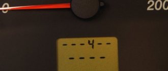
Self-diagnosis VAZ 2110: error codes
To enable self-diagnosis mode, the driver or technician will need to perform a certain sequence of actions.
If everything is done correctly, one of the following symbols will light up on the device:
Also, error 14 VAZ 2110 or another two-digit number will indicate the presence of two problems. Usually, with such a picture, the ciphers are summed up. For example, error 10 VAZ 2110 may indicate problems in circuits No. 4 and 6.
How to reset errors on a VAZ 2110
Typically, the procedure is carried out after repairing the unit for which the fault code is responsible. In this case, the symbol does not disappear - it must be forcibly reset. This is done quite simply. The user is required to enter the service mode (hold down the daily mileage button), then double-click on any control. After completing the manipulations, a code will appear on the display. To eliminate this, the daily mileage button is pressed for 3-4 seconds and the system is reset. The machine exits the dialog box automatically after 30 seconds of inactivity.
Why is a lambda probe needed in a car, location
A lambda probe is necessary to measure the oxygen content coefficient in a combustible mixture. It is always installed in the area of the exhaust pipe before the catalyst and measures the volume of unburned oxygen in the combustion products. This information will allow the ECU to prepare the optimal mixture.
A mixture containing 14.7 parts air and one part fuel burns most efficiently. These are optimal indicators; if oxygen is present in large quantities, then the mixture is lean; if there is less air, then it is rich.
Combustion of a rich mixture is less efficient - a decrease in power and increased fuel consumption can be observed.
Since the engines in cars operate in completely different modes, the optimal ratio of air and fuel may not be observed. Oxygen sensors are used to control the quality of the mixture in power systems.
Based on the signals from the lambda, the ECU can assess the quality of the mixture. If indicators are found that do not meet the standards, the mixture is adjusted.
Operating principle of the oxygen sensor
The principle of operation of the oxygen sensor is quite simple. The lambda probe must compare the readings with some ideal results in order to understand how the percentage of oxygen in the mixture changes, so measurements are taken in two places - atmospheric air and combustion products .
This approach allows the sensor to feel the difference if the fuel mixture ratio changes.
The ECU must receive an electrical impulse from the lambda probe. To do this, the sensor must be able to convert measurements into electrical signals. For measurements, special electrodes are used that can react with oxygen.
Lambda uses the principle of galvanic cells - changing the conditions of chemical reactions leads to a change in the voltage between the two electrodes. When the mixture is rich and the oxygen content is below the lower threshold, then the voltage rises. If the mixture is lean, the voltage will drop.
Next, the impulse that occurs at the stage of chemical reactions is sent to the ECU, where the parameters are compared with the fuel maps stored in the memory. As a result, the operation of the power system is adjusted.
The oxygen sensor operates on chemical reactions, but its design is relatively simple. The main element is a special tip made of ceramic materials. Zirconium dioxide and, less commonly, titanium dioxide are used as raw materials.
The tip is coated with platinum - it is this layer that reacts with oxygen. One side of this tip is in contact with the exhaust gases, the other side with the air in the atmosphere.
The lambda probe electrodes have one feature. So that the reaction is more efficient and the indicators are accurate, measurements of the oxygen content in the exhaust are carried out under certain temperatures.
In order for the tip to reach the performance characteristics and the required electrical conductivity, the temperature of the environment should be 300-400 degrees.
To ensure the required temperature regime, the lambda probe was initially installed in close proximity to the exhaust manifold. This ensured the desired temperature after warming up the internal combustion engine. The sensor did not start working immediately. Before the lambda warmed up enough and began to produce accurate parameters, the ECU used signals from other sensors. The optimal mixture was not prepared during the heating process.
Some oxygen sensor models are equipped with electric heaters. Thanks to them, the lambda can quickly reach operating temperature conditions. Heating uses energy from the vehicle's on-board network.
What does the error indicate?
The error with this code is quite common and is not considered particularly complex. Such a notification tells the driver that the information coming from the first oxygen sensor is incorrect or is issued with violations. You can diagnose the supply of incorrect information from the sensor to the ECU as follows:
What are the symptoms of code P0134?
In some cases, there may be no symptoms other than a stored DTC and CHECK ENGINE light. On the other hand, some consequences may be so severe in other cases that the vehicle becomes undriveable.
Also keep in mind that the severity of one or more symptoms may vary from vehicle to vehicle.
How to check a lambda probe with a multimeter
When there are jerks when driving, increased fuel consumption, and a lighted “check”, then it is worth carrying out diagnostics. These signs may indicate other malfunctions, but if you have a multimeter, you can check the oxygen sensor yourself. Experts recommend checking the lambda by measuring voltages.
But before any measurements, you need to warm up the internal combustion engine. If the lambda is cold, it will not work. It is also recommended to remove the sensor, if possible, and inspect it and the wiring for dirt or damage. If the sensor is deformed, the electrode is scratched or covered with soot or carbon deposits, then it is better to replace it.
Heating circuit voltage measurements
Turn on the ignition, pierce the wires that go to the heater with probes. You can also plug multimeter probes into the connector. The voltage will be approximately equal to the voltage in the on-board network. If the engine is not running, then there may be no voltage.
Usually the plus comes directly to the heater. The minus is supplied by the control unit. If there is no positive, you should check the circuits from the battery to the sensor. If there is no minus, then you need to check the circuit from the ECU to the sensor.
Heater check
You can check the functionality of the oxygen sensor using an ohmmeter. Very often the breakdown is associated with the heating coil or the wiring to it.
To check, an ohmmeter is connected between the heater contacts. If the heater is working properly, the ohmmeter will show a resistance of 2 to 10 ohms. In the heating circuit, the resistance will be from 1 kOhm to 10 mOhm. If there is no resistance, then you should look for a break in the wiring.
Functionality check
Many VAZ-2112 owners ask how to check the lambda probe (oxygen sensor) themselves. To do this you will need to do the following:
- It is necessary to turn off the engine and allow it to cool.
- After this, open the hood of the car and disconnect all contacts leading to the oxygen sensor.
- Take a multimeter and connect the end probes to the lambda probe.
- Then use the “Resistance” mode on the multimeter. If the arrow goes to infinity, then the device is working correctly and the readings are being transmitted correctly.
- In a situation where the arrow shows a value near zero, the measuring device is faulty and needs to be replaced.
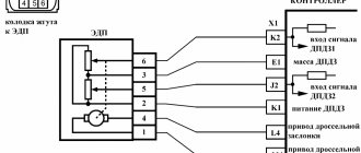
location of oxygen sensor bank1 sensor1 grant, viburnum 2
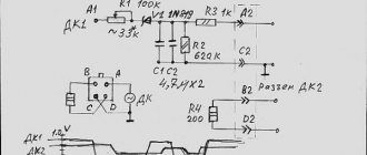
The UDC is installed on the receiving pipe (Fig. 1.1-06). Its sensitive element is located in the exhaust gas flow. The UDC generates a voltage varying in the range of 50...900 mV. This output voltage depends on the presence or absence of oxygen in the exhaust gases and on the temperature of the UDC sensing element. When the UDC is in a cold state, there is no output signal from the sensor, since in this state its internal electrical resistance is very high - several megohms. As the sensor warms up, the resistance drops and the ability to generate an output signal becomes possible. To operate effectively, the UDC must have a temperature of at least 300°C. For quick warm-up after starting the engine, the UDC is equipped with an internal electric heating element, which is controlled by a controller. The duty cycle of heater control pulse signals (the ratio of the duration of the on state to the pulse repetition period) depends on the temperature of the UDC and the operating mode of the engine.
If the sensor temperature is above 300°C, then at the moment of passing through the stoichiometry point, the sensor output signal switches between low level (50...200 mV) and high level (700...900 mV). A low signal level corresponds to a lean mixture (presence of oxygen), a high signal level corresponds to a rich mixture (no oxygen).
Reasons for error p0134
Unlike other errors in the ECU, code p0134 clearly indicates the original source of the problem - this is the first oxygen sensor of the catalyst. Therefore, the appearance of this error can only mean one thing: some problems have arisen in the lambda probe.
However, there may be several specific reasons for the error:
- breakdown of the oxygen sensor itself (natural wear);
- breaks and damage to the lambda probe wiring;
- presence of rust on the connectors;
- Short circuit in the network.
Using professional equipment to diagnose errors helps you quickly and accurately find out the cause of the problem. For example, if the auto scanner produces two errors at once - p0134 and p0171, then this indicates the presence of a short circuit in the network or a wiring break. Accordingly, it is possible to exclude a breakdown of the sensor itself as the cause of the malfunction.
According to existing statistics, in 95% of cases error p0134 appears due to a breakdown of the oxygen sensor itself. And only the remaining 5% of cases occur due to short circuit or insulation damage.
Replacing the lambda probe
In most cases, a part such as a lambda probe cannot be repaired, as evidenced by statements about the impossibility of repair from many automobile manufacturers. However, the inflated cost of such a unit from official dealers discourages anyone from purchasing it. The optimal way out of this situation could be a universal sensor, which costs much less than its native analogue and is suitable for almost all car brands. Also, as an alternative, you can purchase a used sensor, but with a warranty period, or a completely exhaust manifold with a lambda probe installed in it.
However, there are cases when the lambda probe operates with a certain error due to severe contamination as a result of combustion products deposited on it. In order to make sure that this is really the case, the sensor must be checked by specialists. After the lambda probe has been checked and its full functionality has been confirmed, it must be removed, cleaned and reinstalled.
In order to dismantle the oxygen level sensor, it is necessary to warm its surface to 50 degrees. After removal, the protective cap is removed from it and only after that you can start cleaning. It is recommended to use phosphoric acid as a highly effective cleaning agent, which can easily cope with even the most stubborn flammable deposits. At the end of the soaking procedure, the lambda probe is rinsed in clean water, thoroughly dried and installed in place. At the same time, do not forget about lubricating the threads with a special sealant, which will ensure complete tightness.
The structure of a car is very complex, so it needs constant maintenance and timely preventative maintenance. Therefore, if there is a suspicion that the lambda probe is faulty, it is necessary to immediately diagnose its performance and, if the fact of failure is confirmed, replace the lambda probe. Thus, all the most important functions of the vehicle will be maintained at the same level, which will guarantee the absence of further problems with the engine and other important elements of the car.
Replacement problems
When replacing, the old sensor may stick to the pipe. In this case, proceed like this:
Oxygen sensor price
The price of an oxygen sensor will vary by region and model. It ranges from 1000 to 3000 rubles . Buy a lambda probe in specialized stores and only with a guarantee.