All modern cars are equipped with advanced devices for monitoring and recording breakdowns of on-board systems. Standard Lada Vesta error codes are detected and stored in long-term memory until they are read by a third-party device and completely reset. The car itself is a modern car that meets the requirements of advanced standards. The internal components and mechanisms of the car have been modified to the required level of reliability and service life.
On the other hand, motorists often complain about the reliability of electronic components. The on-board electronics malfunction when traveling on unpaved roads or when crossing fords, which causes errors to appear in the systems memory.
How does a mechanic diagnose a P0342 code?
First, the mechanic reads all stored error codes using an OBD-II scanner. He will then check and, if necessary, repair or replace all damaged wires, connectors and other electrical components of the system. The mechanic will then clear the error codes from the PCM memory and recheck the system. If the error code appears again, the mechanic will check the battery charge and also inspect the starter motor. It will then clear the error codes from the PCM memory again and check the system to see if P0342 appears again. This procedure must be performed every time after repair work is performed. This will help determine if the problem is resolved.
Lada Vesta errors decoding and description
The following are the most popular Vesta 1.8 and 1.6 errors associated with power plant components (P):
- 0030/31/32 – violation of the integrity of the sensor circuit installed in front of the neutralizer with a possible short circuit to the body or wiring;
- 0036-38 – similar for DK 2;
- 0106-108 – erroneous data received from the pressure sensor in the intake manifold with an open circuit or short circuit;
- 0111-113 – the same block responsible for the intake air temperature, signal failure;
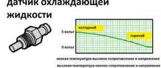
- 0116-118 – malfunction of the antifreeze temperature sensor;
- 0122-123 – the wiring of the throttle position sensor is faulty, the element itself may be damaged;
- 0130 – oxygen sensor has failed;
- 0131-134 – DK1 detected incorrect signal transmission to the on-board computer;
- 0135 – the part described above has failed;
- 0136 – DK2 is out of order;
- 0137/138/140 – breakdown of the DK2 highway;
- 0141 – malfunction of heater DK2;
- 0171/172 – excessively lean or enriched fuel mixture;
- 0201-204 – the injector control lines are out of order, respectively for each cylinder;
- 0217 – excessive heating of the cooling system, you need to stop and wait until the engine cools down;
- 0222/0223 – TPS B lines, produce a high or low signal;
- 0261/264/267/270 – short circuit to the body of the injector circuits for each cylinder in series;
- 0262/265/268/271 – similarly with touching other electrical wiring elements;
- 0300 - the on-board computer has detected multiple misfires - the fuel supply to the engine is turned off;
- 0301-304 – misfires in a single cylinder sequentially, the injectors of the corresponding cylinders are turned off;
- 0327/328 – the fuel mixture knock sensor sends incorrect signals;
- 0335/336 – DPKV circuit is faulty or the sensor itself is broken;
- 0340/342/343 – DPRV has failed or faults have been detected in its line;
- 0351-354 – open circuit for controlling the injector drivers for each cylinder in series;
- 0363 - error p0363 Vesta indicates that there are misfires, which provokes a cutoff of the combustible mixture supply;
- 0422 - the neutralizer is out of order or clogged - a line replacement of the unit is required;
- 0441 – incorrect oxygen flow through the CPA was detected;
- 0443/444/458/459 – there is a problem in the canister purge valve circuit; you need to check the entire line;
- 0480/481 – error p0480 Vesta and its analogue indicate an open circuit of fan relay 1/2;
- 0504 – violation of synchronization of brake pedal signals;
- 0513 – incorrect immobilizer key;
- 0522-523 - error p0523 Vesta and others like it say that the oil pressure sensor is giving an incorrect signal;
- 0560-563 – disturbances in the stability of the vehicle’s on-board network;
- 0601-604 – errors in the ECM;
- 0606 – processor malfunction;
- 0627-629 – failure of the main fuel pump control relay;
- 062F – EEPROM error;
- 0641-643 – there are problems within the sensor power supply circuit;
- 0645-647 – the air conditioner clutch control relay is out of order or there are wiring breaks;
- 0660-662 – the wiring of the valves of the intake length control system is shorted or broken;
- 691/692 – short circuit to the body/on-board circuit RV1;
- 693/694 – similar for RV2;
- 1301-1304 - error 1301 Vesta and the next three points indicate that critical misfires were detected, damaging the converter, for each cylinder sequentially;
- 1335 – the sensor finds the throttle position outside the permissible limit;
- 1336 – similarly for the specified element indicates a TPS mismatch;
- 1388 – similar desynchronization of the gas pedal;
- 1390/1391 – the throttle valve actuator is faulty or does not work correctly;
- 1545 – the position of the throttle valve on the instruments does not correspond to the actual location;
- 1558 – the DZ spring burst or flew off;
- 1559 – PDZ is outside the permissible limit at idle speed;
- 1564 – on-board PDZ systems interruption of zero position adaptation;
- 1570 – the immobilizer control circuit has failed or is damaged;
- 1578/1579 – problems in the remote control drive control system;
- 1602 – voltage to the ECM is lost;
- 1640 – there is an error in the EEPROM program for the ECM;
- 2100-2103 – problems with the electric throttle drive;
- 2105 - error p2105 Lada Vesta indicates incorrect operation of the spark plugs, usually happens after replacing parts;
- 2122/2123 – the signal level of the gas pedal sensor A is too low or high;
- 2127/2128 – similar for sensor B;
- 2135/2138 – mismatch between sensors A and B of the throttle/gas pedal position;
- 2176 – adaptation of the throttle valve drive has not been carried out;
- 2187/2188 – excessively lean/rich air-fuel mixture at idle speed;
- 2270/2271 – no response from DK2 to depletion or enrichment of the fuel mixture;
- 2301/2304/2307/2310 – closing the ignition coils for all cylinders in series with contact with the on-board wiring sections.
Additional comments for troubleshooting P0342
The camshaft position sensor is an integral part of the system that allows the vehicle to operate reliably, smoothly and quietly. If the sensor does not operate properly, symptoms will occur indicating a problem. If the problem is not solved for a long time, it can lead to more serious problems. Therefore, if a P0342 error is detected, it is recommended that you contact a qualified technician as soon as possible to diagnose and resolve the error.
It should also be noted that if this error code is stored in the PCM and the Check Engine Light illuminates, the vehicle will most likely fail an emissions test.
Symptoms of malfunction
The main driver symptom of P0342 is the MIL (Malfunction Indicator Light) illumination. It is also called Check engine or simply “check light”.
They can also appear as:
- The “Check engine” warning light on the control panel will light up (the code will be stored in the ECM memory as a malfunction).
- Decrease in engine power.
- Possible misfires in the engine cylinders. The car engine may also become unstable.
- Floating speed, as well as attempts to stall at idle.
- The engine stalls or has trouble starting.
- Increased fuel consumption.
The vehicle will most likely run with this trouble code. But it may be difficult to start, and there may also be a drop in power and unstable engine operation. To avoid damage to other engine components, if this code is detected, it is recommended that the problem be repaired as soon as possible.
Decoding Vesta errors related to the data bus (U)
- 0001 – pin failure at the physical level;
- 0002 – block wiring is damaged;
- 0009 – short circuit of lines touching the on-board circuit or body;
- 0073 – diagnostic output disabled;
- 0121 – there is no signal from the ABS unit;
- 0122 – ESP controller does not respond to the request;
- 0155 – open circuit of the control panel;
- 0167 – the immobilizer does not respond to the diagnostic scanner request;
- 0415 – standard error of ABS Vesta;
- 0416 – similar for the ESP system;
- 0426 – the immobilizer transmits incorrect information to the on-board computer system.
Motor Master Club
- ANNOUNCEMENTS, INFORMATION
- ↳ RULES
- ↳ Announcements
- ↳ Articles
- TECHNICAL SUPPORT
- ↳ Installation and update of “Motor-master” software
- ↳Motor-scan (scanner)
- ↳ Archive (questions about the scanner)
- ↳ Motor-Loader (loader)
- ↳ DiSco, DiSco-Express, Motor Tester, Test Master
- ↳ History of changes
- ↳ Other devices and sensors
- ↳ Alphameter ALC
- ↳ Archive (Questions to the manufacturer)
- MOTOR-MASTER
- ↳ Disco (oscilloscope, recorder, etc.)
- ↳ Motor-Tester (ignition systems)
- ↳ DiSco-Express (express diagnostics)
- ↳ Test Master (testing sensors and MI)
- ↳ Motor-Loader (loader)
- ↳ General questions
- ↳ Chip tuning VAZ, GAZ, UAZ
- ↳ Chip tuning of foreign cars
- ↳ Odometers (odometer programmer)
- ↳ General questions
- ↳ Removal and disassembly of instrument panels
- ↳ Help for newbies
- DIAGNOSTICS
- ↳ Diagnostics VAZ, GAZ, UAZ, ZAZ
- ↳ VAZ
- ↳ GAS
- ↳ UAZ
- ↳ ZAZ
- ↳ Diagnostics of foreign cars
- ↳ Europe
- ↳Japan
- ↳ Asia
- ↳America
- ↳ Diagnostics of diesel engines
- ↳ “Iron” questions
- ↳ Engines
- ↳ Power systems (hardware)
- ↳ Chassis
- ↳ Transmissions
- ↳ Body
- ↳ Exhaust system
- ↳ Lubricants
- ↳ Tools and consumables
- ↳ Selection of spare parts and components
- ↳ Diagnostic devices
- ↳ Electrical and electronics
- ↳ Autoelectrics
- ↳ Alarm and music
- ↳ Repair of ECU and other units
- ↳ Miscellaneous
- ↳ Section for beginners and car owners
- AUTHOR'S MATERIALS and PROGRAMS
- ↳ Section information
- ↳ Vijar
- ↳ kdv
- ↳SAW
- ↳ DataLook (program for configuring firmware)
- ↳ sts1968
- COMMERCIAL FIRMWARE
- ↳ About the Motor-Master Chip firmware store
- ↳ Articles and materials for beginners and more…
- ↳ Chip tuning
- ↳ Diagnostics
- ↳ Devices and accessories
- ↳ Information materials
- ↳ Representatives of Motor Master
- ↳ VAZ
- ↳ UAZ
- ↳ KOREA
- ↳Kefico 797
- ↳ Kefico M(G)798 Kia-Hyundai
- ↳ Bosch ME17911(12) Kia-Hyundai
- ↳Bosch ME17921
- ↳ RENAULT
- ↳EMS3132
- ↳ Valeo 40/42
- ↳EMS3120
- ↳EMS3125
- ↳CHEVROLET
- ↳ Simtec 7.6
- ↳ Announcements
- GENERAL ISSUES
- ↳ General questions
- ↳ Site operation
- ↳ Communication
- ↳ Flea market
- ↳ Car services (offer of services)
- ↳ All about our work
- ↳ Computers, laptops, etc.
- Moved topics
Re: 2114 high signal level of the phase sensor
I couldn't find a topic for my question, so I'll ask it here. The essence of the question: VAZ 2115 error: low signal level from the phase sensor. The client has already changed 3 sensors. This car came to me with a request to turn off the 2nd DC (leave the 1st DC partially). I did my job, but the client came with a complaint “the check light is on”, I connect the scanner and take a look. I say that there is an error in the phase sensor, but he tells me that he has already changed 4 sensors, but the result is the same. The sensor that was on his car was really “dead”, the voltage at the output “C” of the connector was really 0V. He replaced the sensor with another (which he was told was faulty) - the voltage rose to the required 11.8 V, installed it on the machine, the oscilloscope showed the pulses, even, with the marks in place. Released the client. Yesterday he arrived - the check light is on again, the error is again low signal level from the phase sensor. I connect, look, it’s really 0v. I disconnect the sensor (on the connector) 11.8 V, connect it to 11.8. I start the car - it works, the pulses go. (!) BUT the pulses go until you turn off the ignition and the main relay turns off, after which 0.43 V hangs at terminal “C” for some time, and then the voltage rises to 1, 35c. After this, turning on the ignition, the sensor displays 0.38V, which does not rise when starting. If you disconnect and connect the sensor connector, the voltage is restored to 11.8 and the sensor starts working. Again until the ignition is turned off. That's the problem. Today the client will bring another phase sensor, I'll try it. But for some reason I’m sinning on the ECU (it has a Bosch M7.3). If all else fails, I will reflash it without a phase sensor. Has anyone encountered this problem?
On which cars is this problem most common?
The problem with code P0342 can occur on different machines, but there are always statistics on which brands this error occurs more often. Here is a list of some of them:
- Cadillac (Cadillac CTS)
- Chery (Chery A15, Amulet)
- Chevrolet (Chevrolet Aveo, Captiva, Lanos, Lacetti, Optra, Rezzo, Spark)
- Chrysler
- Citroen (Citroen C4)
- Daewoo (Daewoo Lanos, Leganza, Matiz, Nexia, Nubira)
- Ford (Ford F-150)
- Hyundai (Hyundai Accent)
- Opel (Opel Corsa, Frontera)
- Peugeot (Peugeot 308, 3008)
- Skoda (Skoda Octavia, Fabia)
- Toyota
- Volkswagen (Volkswagen Passat)
- VAZ 2110, 2112, 2114, 2115
- Gazelle
- Lada Vesta, Kalina, Niva, Priora
- UAZ
With fault code P0342, you can sometimes encounter other errors. The most common ones are: P0008, P0022, P0335, P0340, P0341, P0343, P0345, P0346, P0347, P0348, P0349, P0365, P0366, P0367, P0368, P0369, P0390, P0391, P0392, P039 3, P0394, P1133, P1396 .
Source
Diagnostic methods
If error P2135 is recorded in the ECU memory, you should check the functionality and serviceability of the sensor. After all, it is the controller that determines the position in which the throttle assembly, that is, the damper, is located, is the culprit in this situation.
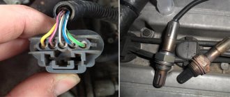
The whole point of diagnosing error P2135 comes down to checking the position sensor. To do this, it is recommended to perform the following operations:
- Arm yourself with a multimeter, select the dialing mode and connect to the contacts on the position sensor connector.
- By simulating the movements that the throttle makes, you should check how the sensor will react to these changes. The damper should be moved to its extreme positions. If wheezing appears on the multimeter, this indicates a malfunction.
- Additionally, the resistance of the sensors should be checked. Each car has its own optimal performance. They are specified in the technical documentation. Most often these values are around 10 kOhm.
- The resistance can be checked without removing the sensor from the throttle assembly. Here you need to disconnect the controller block and turn on the ignition. Now the plus of the multimeter is connected to the power wire in the sensor harness block, and the minus is placed on engine ground.
- In this case, numbers in the range from 4.8 to 5.2 V should appear on the measuring device (multimeter).
- Turn off the ignition and perform the same resistance test as suggested with the sensor removed.
- When the damper closes, the resistance should be less. When the damper is fully opened, the resistance increases.
- To check the sensor on a car with an electronically controlled throttle, the gas pedal is pressed to the floor, and then the voltage readings are checked with a multimeter. The sum of the readings from the first and second sensor should be about 5 V. This is considered a reference value indicating that the sensor is working.
auto electrician
Code P1336 Monitoring the control of the throttle valve drive, mismatch of signals from sensors “A” / “B” of the throttle position
Code P1336 is entered if: - the ignition is on; — the sum of the signals TPS A and TPS B differs from the reference voltage of 5 V by more than 0.3 V for 0.5 s.
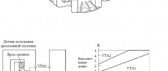
The malfunction indicator lights up 5 s after the fault code appears. Description of checks
1 Using a scan tool, check whether code P1336 is active at the time of diagnosis. 2 The check is carried out in accordance with the map for code P2135. Diagnostic information Diagnostic tool in “1 Parameters” mode; 6 Add. Options; 3 ADC inputs” shows the signals of TPS A (UDKP1) and TPS B (UDKP2) in volts. When the throttle valve is opened, the TPS A signal increases, the TPS B signal decreases. With the throttle valve fully closed, the TPS A signal should be in the range of 0.3...0.6 V, the TPS B signal should be in the range of 4.4...4.7 V. The controller recalculates the voltage signals of TPS A and TPS B into the percentage of throttle opening flaps. The diagnostic tool is in “1 Parameters” mode; 1 General view" displays the percentage of throttle valve opening WDKBA, which is calculated as the arithmetic average of the signals TPS A (%) and TPS B (%). 0% corresponds to a fully closed throttle. 100% corresponds to the maximum throttle opening per lever. The signals TPS A and TPS B are mismatched if the following condition is met: |5 V – (UDKP1 + UDKP2)| > 0.3 V If a mismatch between the TPS A and TPS B signals is detected, the engine control system will operate in emergency mode until the end of the current trip: de-energizing the electric throttle drive and limiting engine speed (2500 rpm). If the EDM or ECM is replaced, or the controller is reset using the diagnostic tool (mode “5 Additional tests; 1 ECM reset with initialization”), it is necessary to perform the throttle valve zero adaptation procedure. To do this, with the car standing, you need to turn on the ignition, wait 30 seconds, turn off the ignition, and wait until the main relay turns off. Adaptation will be interrupted if: — the engine is cranking; — the car is moving; — the accelerator pedal is pressed; — engine temperature below 5 °C or above 100 °C; — ambient air temperature below 5 °C. If the electric throttle actuator is de-energized, the throttle valve is held in the Limp home position (6-7%) using direct and return springs.
Related pages:
- Error P1336 Lada Priora, Kalina, 4x4 - ME17.9.7 /…
- Error P1336 Lada Vesta
- Errors P0122, P0123, P0222, P0223 Lada Kalina 2, Granta
- Lada Vesta error P0122, P0123
- Error P1545 Lada Priora, Kalina, 4x4 - ME17.9.7 /…
- Error P1564 Lada Vesta
Re: 2114 high signal level of the phase sensor
A high level is, as you were correctly told, a cliff. When the sensor is disabled, the level will be “High”. The sensor is checked very easily: remove the connector from the sensor, find 1 contact of the connector (wire white/black) - this is ground (GND), on the next contact (pink/black, I think) - +12V (power supply to the sensor, this is constant power from the output of the main relay ), on pin 3 (pink wire, I think) when the sensor is disconnected there should be 11.8-12.2 V, this is the signal power supply from the ECU. If all these voltages are present, then we proceed to checking the phase sensor itself: pull out the sensor, connect it to the connector, use a tester to test the negative probe on 1 contact, the positive probe on 3 contact. The voltage should be 11.8-12.2V, now bring a knife, screwdriver or flat metal plate to the end of the sensor (where type 13K is written) - the voltage should drop to 0V, removing the plate the voltage will rise to 11.8-12.2 volts. If all these conditions are met, the sensor is operational.
Diagnostics using the dashboard
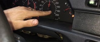
It is advisable for the owner of the Russian model we are considering to remember all the error codes that may periodically occur in the system. In addition, it is recommended that you learn how to diagnose the dashboard yourself. It is designed to reflect error codes that occur in the electronic components of the Lada Kalina.
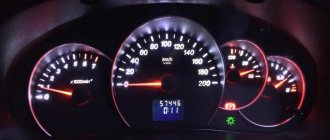
To start the diagnostic process, you will need to press a button that records the daily mileage. While holding it, turn on the ignition by turning the appropriate key. If this manipulation is performed correctly, the arrows on the scales of the speedometer, tachometer and auxiliary indicators will begin to move along a circular path, moving from the initial to the final position.
Upon completion of this movement of the arrows, the owner will need to switch the screen to another mode. This will be done by a special button located on the wiper switch under the steering wheel. Pressing displays a picture with performance indicators of a wide range of devices controlled by the ECU. The software version of the complex is also displayed here - self-diagnosis.
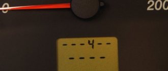
After updating the information three times, the error codes themselves appear on the device, expressed in digital form.
Let's look at the list of errors by number:
- No. 2 – the error indicates the presence of a deviation of the voltage indicator in the on-board network from the nominal parameter;
- No. 3 – “speaks” of a failed fuel level sensor in the tank;
- No. 4 - the so-called error 4 is activated if there is a break in the antifreeze temperature sensor circuit in the cooling circuit or the component itself has become unusable;
- No. 5 – indicates a breakdown of the outside temperature sensor;
- No. 6 - confirms the fact of engine overheating;
- No. 7 – states a critically low level of oil pressure in the corresponding engine circuit;
- No. 8 – error 8 for non-working brake components of the car;
- No. 9 – confirms the fact of battery discharge.
The “E” symbol deserves special attention, which indicates the presence of errors contained in the “EEPROM”. Each malfunction, including error 4 and error 8, requires attention from the car owner.
Self-diagnosis
The easiest and most common way to diagnose error codes on a VAZ Kalina is to search using the on-board network. The procedure looks like this.
Insert the key into the lock cylinder. Next, hold down the RESET key and, without releasing it, turn on the ignition. In this case, the device will automatically switch to diagnostic mode. At the same time, all the indications will light up, and the instrument arrows will make a full circle.
You should pay attention to the arrows and indicators - if any diode does not light up, you need to check the device for which the element is responsible. On the right steering column lever there is a button for scrolling through the options - you need to scroll to the required position (error codes). Next, the display will show the general error number; to reset the index, you need to hold RES for three seconds.
Note! The indicated sequence is relevant for Lada Kalina of the first and second modifications.
The position of the error codes will show one of the indices on the display:
- “2” – there is a surge in the BS power supply – a possible short circuit in the wiring;
- “3” – rupture of lines, or failure of the float inside the gas tank;
- error 4 Lada Kalina says that the coolant temperature sensor is broken or malfunctioning;
- “5” – the thermometer has gone astray, the element may be damaged or the circuit may be broken;
- “6” – exceeding the maximum permissible temperature of the internal combustion engine block, while the acoustic alarm is working;
- “7” – exceeding the permissible pressure thresholds inside the oil line;
- “8” - on a Lada Kalina car, error 8 appears when there is a malfunction of the calipers or a breakdown in the hydraulic drive line;
- “9” – critical voltage drop in the battery;
- “E” – incorrect reading or display of the EEPROM information module.
To return to the original part, it is enough to hold RES for 30 s. The disadvantage of this method is minimal accuracy - the procedure shows in which direction to look for a breakdown, but not a specific node. So, it is possible to understand exactly where the failure occurred only by the following method.