It is impossible to imagine the operation of any car without any devices powered by electric current. Starting from the most basic thing - supplying a spark, and ending with secondary functions that affect the comfort of the driver and passengers - heated seats, LCD monitor and audio system, GPS navigator, etc., they all require a certain amount of current for their operation.
There are not so many electrical appliances in the VAZ 2108 car, but still, they need constant recharging. Where it comes from, how it gets to each device, what methods of protection it has, etc., we will look at in this article.
Device and principle of operation
First, you need to determine: what type of power supply to the engine is currently subject to discussion. After all, the carburetor and the injector have completely different devices, and each of them has its own electrical circuit. You and I will talk about the type of power supply for the VAZ 2108 engine - a carburetor.
The wiring originates from the battery. Typically, a 12 volt (6 amp) battery is installed. On its way to various appliances, electricity passes through the fuse box. Further, it stabilizes its power using a number of devices: a switch, a voltmeter and an econometer.
After this, the electrical circuit is distributed directly to the main components of the VAZ 2108 devices. Let's start with the lighting devices. These include: headlights, low beam and high beam, engine compartment lighting, taillights, turn signals, interior lighting, and license plate lighting. Each of the above elements receives a different amount of energy. For example, for high beams, the current will be more powerful than for dimensions.
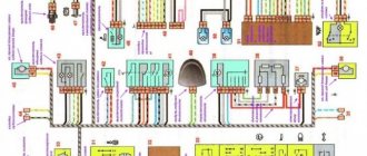
Complete wiring diagram for Lada 2107
As for the operation of the VAZ 2108 engine, the following devices are required: a generator, control systems responsible for the carburetor, starter, ignition coil, distributor and spark plugs. The wiring diagram transfers electricity from the ignition coil to the spark plugs. In this case, while the engine is running, the generator is turned on. The distributor is responsible for distributing the spark between the combustion chambers of the cylinders. Each cylinder has its own stroke sequence, which is determined by the engine diagram.
The control systems responsible for the carburetor must open the valves in time, helping to form the correct combustible mixture in the float chamber. They also regulate the operation of the solenoid valve.
The carburetor has a simpler wiring diagram than the injector. This is because the injector circuitry involves electrically controlling the injection and mixture formation, while the carburetor does most of this work mechanically.
Further, the electrical voltage circuit in the VAZ 2108 car includes devices designed to improve driving safety and comfort. These include: air conditioning, heater, windshield and headlight washers, radio, and horn.
Also, the VAZ 2108 car has sensors that determine the temperature and level of fluids necessary for engine operation. Each of them is also powered by a battery. Sensor indicators are displayed on the instrument panel so that the driver can see them. The dashboard of the VAZ 2108 includes 16 indicator lights, a speedometer and a tachometer.
Diagram of instrument warning lamps
What can be changed in the electrical circuit
Let's figure out what exactly car owners undergo alterations.
Moreover, we will indicate only those alterations that are not prohibited by the manufacturer and current regulations:
- Installation of a new instrument panel;
- Alteration of internal (interior) lighting;
- Installation of additional turn signal indicators in the rear view mirrors;
- Installation of additional headlights (fog lights);
- Installation of an acoustic and multimedia system;
- Immobilizer installation.
Wiring diagram for VAZ 2109i with a high panel
For reference: the visual differences between the standard panel and the “high” one are that the radio compartment is moved to the level of the dashboard. Accordingly, the wiring on the VAZ 2109 under the instrument panel must be replaced.
Interior modifications
Many owners come to mind with the desire to improve the lighting in the car interior.
Let us remind you that inside a passenger vehicle there are several places equipped with lighting sources:
- The salon itself (interior lighting);
- Glovebox;
- Cigarette lighter;
- Instrument panel (instrument cluster lamp and symbol lamp)
Layout of incandescent lamps for a VAZ 2109 car
If you, as the owner, like a high panel in the cabin, then you cannot do without replacing the standard wiring. Because the:
- Control devices have a different location on the panel;
- The standard length of wires is not enough;
- Terminal blocks may also differ.
Electrical wiring for a VAZ 2109 in the process of connecting to devices
Accordingly, without replacing the electrical wires it will not be possible to use:
- instrumentation;
- on/off buttons for various devices.
Differences in the terminal blocks of the “low” and “high” instrument panel
As for making changes to the instrument panel lighting, today there are sets of special lamps on sale along with the wiring with which they are connected to the car’s electrical network.
Why do you think the owner needs a GAZelle wiring diagram?
Tuned instrument panel lighting for VAZ 2109
You can install such kits yourself; it is only important to adhere to accuracy and safety rules.
Advice: carry out all electrical wiring replacements and connecting instrumentation only with the battery disconnected.
Malfunctions
If the electrical circuit of the car has any malfunctions, then they need to be eliminated as quickly as possible. Otherwise, this may affect the condition of the devices for which this circuit is responsible. In the event of a malfunction or short circuit, at best, some element of the electrical system will fail, and at worst, the car may catch fire.
In order to determine the state of any system, you need to pull out the fuse that is responsible for the circuit you are interested in. Inside the fuse there is a contact, which, in the event of a voltage drop or short circuit, simply burns out. In this case, it is necessary to inspect each element of the affected circuit. It is better to do this under the supervision of a specialist. Since electrical faults can end very sadly.
Prevention measures
What preventive measures will help maintain the health of electrical wiring:
- All problems that arise in the operation of electrical devices must be resolved as quickly as possible. If there are a lot of them, normal operation of the car will be impossible.
- When installing new devices, the wiring should be laid where there are no rubbing parts and mechanisms, this will preserve its integrity . In addition, when laying, keep in mind that all wires must be reliably insulated.
- The use of homemade fuses in the mounting block is not permitted. If the fuse element has blown, then homemade devices (coins or jumper wires) can be installed only to get to the nearest store. Using such fuses can cause short circuits and even fire, so be careful.
- Periodically diagnose the performance of the generator, in particular, we are talking about its belt. It is necessary to ensure that the strap is always properly tensioned, since insufficient or excessive tension will also affect the operation of the electrical system.
- Twice a year, charge the battery, check the presence of electrolyte in the banks, and visually inspect the case for damage or cracks. Damage and cracks in the structure will lead to leakage of electrolyte, which, in turn, will cause the device to discharge.
- Try not to use cheap Chinese devices and appliances, for example, cigarette lighter splitters. As you know, the cigarette lighter socket is designed for a certain power, and if you decide to connect several devices to it at the same time, the load on the socket will increase significantly.
Have you encountered problems with wiring in your car?
Survey
- Yes
- No
- I don’t know (I don’t repair my car)
Loading …
Electrical wiring diagrams
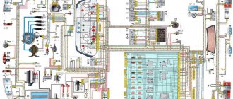
2108 with low instrument panel with mounting block type 17.3722
1 – block headlight; 2 – gear motor for headlight cleaner*; 3 – engine compartment lamp switch; 4 – sound signal; 5 – electric motor of the engine cooling system fan; 6 – fan motor activation sensor; 7 – generator; 8 – solenoid valve for turning on the headlight washers*; 9 – solenoid valve for turning on the rear window washer* (not installed on the VAZ-21099); 10 – solenoid valve for turning on the windshield washer; 11 – electric motor for glass washer; 12 – oil pressure warning lamp sensor; 13 – carburetor solenoid valve; 14 – carburetor limit switch; 15 – spark plugs; 16 – plug socket for a portable lamp; 17 – engine compartment lamp; 18 – ignition distributor sensor; 19 – carburetor solenoid valve control unit; 20 – windshield wiper gearmotor; 21 – switch; 22 – ignition coil; 23 – starter; 24 – top dead center sensor of the 1st cylinder**; 25 – diagnostic block**; 26 – starter activation relay; 27 – coolant temperature indicator sensor; 28 – reverse light switch; 29 – battery; 30 – brake fluid level sensor; 31 – mounting block; 32 – parking brake warning lamp switch; 33 – brake light switch; 34 – glove box lighting lamp; 35 – heater fan electric motor; 36 – additional resistor of the heater electric motor; 37 – heater fan switch; 38 – backlight lamp for heater levers; 39 – cigarette lighter; 40 – rear window heating switch; 41 – rear fog light switch; 42 – fog light circuit fuse; 43 – alarm switch; 44 – external lighting switch; 45 – ignition relay; 46 – ignition switch; 47 – steering column switch; 48 – instrument lighting switch; 49 – side direction indicator; 50 – lamp switch on the front door pillar; 51 – lamp switch on the rear door pillar (not installed on VAZ-2108 and VAZ-21083); 52 – lampshade; 53 – sockets for connecting individual interior lighting to the lampshade; 54 – switch for the carburetor air damper warning lamp; 55 – turn signal indicator lamp; 56 – indicator lamp for external lighting; 57 – rear fog light indicator lamp; 58 – backup warning lamp; 59 – control lamp for high beam headlights; 60 – indicator lamp for heated rear window; 61 – speedometer VAZ 2108; 62 – instrument cluster; 63 – instrument cluster lighting lamps; 64 – coolant temperature indicator; 65 – voltmeter; 66 – fuel level indicator with reserve indicator lamp; 67 – econometrician; 68 – “STOP” indicator lamp; 69 – battery charge indicator lamp; 70 – control lamp for the carburetor air damper; 71 – hazard warning lamp; 72 – brake fluid level warning lamp; 73 – parking brake warning lamp; 74 – oil pressure warning lamp; 75 – rear light; 76 – sensor for level indicator and fuel reserve; 77 – pads for connecting to the rear window heating element; 78 – license plate lights; 79 – rear window wiper gear motor* (not installed on VAZ-21099)
* Installed on parts of manufactured cars. ** Not installed since 1995
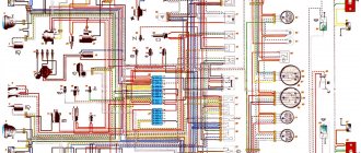
2108 with high instrument panel with mounting block type 17.3722
1 – block headlight; 2 – gear motor for headlight cleaner; 3 – fog lamp; 4 – sound signal; 5 – electric motor of the engine cooling system fan; 6 – engine compartment lamp switch; 7 – fan motor activation sensor; 8 – wire lugs connected to sensor 7 in case of installation of a mounting block type 17.3722; 9 – connectors for connecting to front brake pad wear sensors; 10 – washer fluid level sensor; 11 – solenoid valve for turning on the headlight washer; 12 – solenoid valve for turning on the rear window washer (not installed on the VAZ-21099); 13 – solenoid valve for turning on the windshield washer; 14 – windshield washer motor; 15 – oil level sensor; 16 – generator; 17 – oil pressure warning lamp sensor; 18 – carburetor limit switch; 19 – spark plugs; 20 – carburetor solenoid valve; 21 – engine compartment lamp; 22 – ignition distributor sensor; 23 – carburetor solenoid valve control unit; 24 – windshield wiper gearmotor; 25 – ignition coil; 26 – starter; 27 – switch; 28 – starter activation relay; 29 – coolant temperature indicator sensor; 30 – brake fluid level sensor; 31 – reverse light switch; 32 – battery; 33 – relay for turning on fog lights; 34 – coolant level sensor; 35 – mounting block; 36 – parking brake warning lamp switch; 37 – brake light switch; 38 – door lock control unit; 39 – cigarette lighter; 40 – glove box lighting lamp; 41 – heater fan electric motor; 42 – additional resistor of the heater electric motor; 43 – heater fan switch; 44 – backlight lamp for heater levers; 45 – gearmotors for electric windows of the front doors; 46 – gearmotors for locking front door locks; 47 – gearmotors for locking rear doors; 48 – headlight cleaner switch; 49 – power window switch for the right front door; 50 – ignition switch; 51 – power window switch of the left front door; 52 – ignition relay VAZ 2108; 53 – pads for connecting to the heating elements of the front seats; 54 – right front seat heating switch; 55 – left front seat heating switch; 56 – relay for turning on the heating of the front seats; 57 – front seat heating circuit fuse; 58 – instrument lighting switch; 59 – steering column switch; 60 – indicator lamp for turning on the heated rear window; 61 – rear window heating switch; 62 – control lamp for turning on fog lights; 63 – fog lamp switch; 64 – indicator lamp for turning on the rear fog light; 65 – rear fog light switch; 66 – side direction indicator; 67 – lamp switch on the rear door pillar (not installed on VAZ-21083); 68 – lamp switch on the front door pillar; 69 – canopy for individual interior lighting; 70 – lampshade; 71 – external lighting switch; 72 – instrument cluster; 73 – switch for the carburetor air damper warning lamp*; 74 – alarm switch; 75 – warning lamp for turning on the hazard warning lights; 76 – block for connection to the trip computer; 77 – rear light; 78 – block for connection to the rear window heating element; 79 – rear window wiper motor reducer (not installed on VAZ-21099); 80 – blocks for connecting to an additional brake light; 81 – license plate lights; 82 – level indicator and fuel reserve sensor
* Not installed on vehicles equipped with a carburetor with a semi-automatic starting device.
2108 with high instrument panel with mounting block type 2114-3722010
1 – block headlight; 2 – gear motor for headlight cleaner; 3 – fog lamp; 4 – sound signal; 5 – electric motor of the engine cooling system fan; 6 – engine compartment lamp switch; 7 – fan motor activation sensor; 8 – wire lugs connected to sensor 7 in case of installation of a mounting block type 17.3722; 9 – connectors for connecting to front brake pad wear sensors; 10 – washer fluid level sensor; 11 – solenoid valve for turning on the headlight washer; 12 – solenoid valve for turning on the rear window washer (not installed on the VAZ-21099); 13 – solenoid valve for turning on the windshield washer; 14 – windshield washer motor; 15 – oil level sensor; 16 – generator; 17 – oil pressure warning lamp sensor; 18 – carburetor limit switch; 19 – spark plugs; 20 – carburetor solenoid valve; 21 – engine compartment lamp; 22 – ignition distributor sensor; 23 – carburetor solenoid valve control unit; 24 – windshield wiper gearmotor; 25 – ignition coil; 26 – starter; 27 – switch; 28 – starter activation relay; 29 – coolant temperature indicator sensor; 30 – brake fluid level sensor; 31 – reverse light switch; 32 – battery; 33 – relay for turning on fog lights; 34 – coolant level sensor; 35 – mounting block; 36 – parking brake warning lamp switch; 37 – brake light switch; 38 – door lock control unit; 39 – cigarette lighter; 40 – glove box lighting lamp; 41 – heater fan electric motor; 42 – additional resistor of the heater electric motor; 43 – heater fan switch; 44 – backlight lamp for heater levers; 45 – gearmotors for electric windows of the front doors; 46 – gearmotors for locking front door locks; 47 – gearmotors for locking rear doors; 48 – headlight cleaner switch; 49 – power window switch for the right front door; 50 – ignition switch; 51 – power window switch of the left front door; 52 – ignition relay; 53 – pads for connecting to the heating elements of the front seats; 54 – right front seat heating switch; 55 – left front seat heating switch; 56 – relay for turning on the heating of the front seats; 57 – front seat heating circuit fuse; 58 – instrument lighting switch; 59 – steering column switch VAZ 2108; 60 – indicator lamp for turning on the heated rear window; 61 – rear window heating switch; 62 – control lamp for turning on fog lights; 63 – fog lamp switch; 64 – indicator lamp for turning on the rear fog light; 65 – rear fog light switch; 66 – side direction indicator; 67 – lamp switch on the rear door pillar (not installed on VAZ-21083); 68 – lamp switch on the front door pillar; 69 – canopy for individual interior lighting; 70 – lampshade; 71 – external lighting switch; 72 – instrument cluster; 73 – switch for the carburetor air damper warning lamp*; 74 – alarm switch; 75 – warning lamp for turning on the hazard warning lights; 76 – block for connection to the trip computer; 77 – rear light; 78 – block for connection to the rear window heating element; 79 – rear window wiper motor reducer (not installed on VAZ-21099); 80 – blocks for connecting to an additional brake light; 81 – license plate lights; 82 – level indicator and fuel reserve sensor
Useful: Pinout, connection diagram and checking the VAZ ignition coil
* Not installed on vehicles equipped with a carburetor with a semi-automatic starting device.
Electrical supply diagram
These are the main components of the VAZ-2104 power supply system.
Its full diagram is presented below:
| 1 | Block headlights (includes low and high beam lamps, front dimensions) | 40 | Lamp switches (in door pillars) |
| 2 | Side turn signals (located on the fenders) | 41 | Body interior lamp |
| 3 | battery | 42 | Rear window heating switch with indicator light |
| 4 | Starter relay | 43 | Handbrake control |
| 5 | Electro-pneumatic carburetor valve (idle speed) | 44 | Rear PTF activation control |
| 6 | TDC sensor of the first cylinder | 45 | Checking the brake fluid level |
| 7 | Starter | 46 | Switch for washing and cleaning the rear window |
| 8 | Carburetor microswitch | 47 | Hazard switch |
| 9 | Electric motors for headlight cleaners | 48 | Handbrake control relay breaker |
| 10 | Generator | 49 | Turn signal switch |
| 11 | Sound signals | 50 | Headlight switch |
| 12 | Candles; | 51 | Horn switch |
| 13 | Engine compartment lamp | 52 | Switch for washing and cleaning glass and headlights |
| 14 | Coolant temperature sensor | 53 | Warning lamp block |
| 15 | Oil pressure lamp sensor | 54 | Switch for washing and cleaning glass and headlights |
| 16 | Distributor-breaker | 55 | Egnition lock |
| 17 | Windshield washer motor | 56 | Instrument panel lighting switch |
| 18 | Coil | 57 | PTF switch in the rear headlights |
| 19 | Brake fluid level sensor | 58 | Coolant temperature indicator |
| 20 | Headlight washer motors | 59 | Dashboard |
| 21 | Pneumatic valve control unit | 60 | Oil pressure check |
| 22 | Diagnostic block | 61 | Gasoline level indicator with reserve control |
| 23 | Windshield wiper relay | 62 | Battery charge control |
| 24 | Turn signal and emergency flasher relay; | 63 | Voltmeter |
| 25 | Window cleaning system motor; | 64 | Speedometer |
| 26 | Socket for connecting a portable lamp; | 65 | Checking side lights |
| 27 | Brake light switch | 66 | Turn signal control |
| 28 | Engine with interior heating | 67 | High beam control |
| 29 | Heating motor resistor | 68 | Dashboard light bulb |
| 30 | Handbrake warning lamp switch | 69 | Engine switch with ventilation and heating |
| 31 | Reverse light switch | 70 | Rear window washer motor |
| 32 | Mounting block | 71 | Rear block lights |
| 33 | Low beam relay | 72 | License plate lights |
| 34 | High beam relay | 73 | Rear window heating element |
| 35 | Jumper (instead of horn relay) | 74 | Rear window wiper motor |
| 36 | Relay for turning on the headlight washer and cleaning system | 75 | Luggage compartment lamp |
| 37 | Heated rear window relay | 76 | Gasoline level and reserve sensor |
| 38 | Glove box light | 77 | Ignition relay |
| 39 | Cigarette lighter |
Note that initially only export models of the VAZ-2104 were equipped with this electrical equipment system. It became standard for the subsequent modification of the station wagon - 21043.
For comparison, below is a diagram of the electrical equipment of the VAZ-2105, which was standard for the first station wagon models:
The diagram shows that the first station wagons were not equipped with a rear window heating and cleaning system, headlight washers and cleaners, as well as their control mechanisms. The rest of the electrical circuit is identical.
The electrical circuit of the VAZ-2104 injector is different in that this car already uses electrical equipment borrowed from the VAZ-2107 injection model. This modification of the station wagon was designated VAZ-21047 and it was the last in the history of this car.
Diagram of the VAZ-2104 dashboard, control sensors
The driver monitors the operation of the power plant and car systems using sensors installed on the dashboard in the cabin.
I – temperature sensor; II – instrument panel; III – oil pressure lamp; IV – gasoline level sensor; V – circuit diagram for connecting electrical devices.
| 1 | Thermistor | 27 | Voltmeter |
| 2 | Contact spring | 28 | Dashboard |
| 3 | cylinder head | 29 | Gasoline level indicator |
| 4 | Paper insulation | 30 | Fuel reserve warning lamp |
| 5 | Frame | 31 | PTF rear light switch |
| 6 | Lid | 32 | Lubricant Pressure Sensor Filter |
| 7 | Pointer balancer | 33 | Spring |
| 8 | Permanent magnet arrow axis | 34 | Movable contact |
| 9 | Frame with sensor coils | 35 | Fixed contact (massed) |
| 10 | Protection diode | 36 | Diaphragm |
| 11 | External lighting switch | 37 | Crankcase |
| 12 | Oil pressure lamp | 38 | Reserve warning lamp contact |
| 13 | Coolant temperature gauge | 39 | Rheostat |
| 14 | Battery charge indicator lamp | 40 | Rheostat moving contact |
| 15 | Control lamp block | 41 | Gasoline level and reserve sensor |
| 16 | Brake fluid level lamp | 42 | Float with lever |
| 17 | Handbrake lamp | 43 | battery |
| 18 | PTF switching lamp | 44 | Generator |
| 19 | Speedometer | 45 | Oil pressure sensor |
| 20 | Odometer | 46 | Coolant temperature sensor |
| 21 | Rear defogger switch | 47 | Brake fluid level sensor |
| 22 | Dashboard mounting screw caps | 48 | Mounting block |
| 23 | Interior ventilation and heating fan switch | 49 | Egnition lock |
| 24 | High beam warning light | 50 | Handbrake lamp breaker relay |
| 25 | Turn signal lamp | 51 | Handbrake lamp switch |
| 26 | Exterior lamp |
Devices that provide comfort include a heating and ventilation system, a cigarette lighter, and small lighting fixtures.
To ensure safety and prevent burnout of electrical appliances, all wiring is insulated. Additionally, all equipment is powered through fuses, which are collected in one unit. That is, for example, if the dimensions do not work, there is a high probability that there is a short circuit in the electrical wiring through which these lighting devices are powered. The electrical diagram of the VAZ-2104 fuse box is printed on its cover, which allows you to quickly find which section of the circuit and equipment fuse has blown.
What elements does the diagram include?
The main components of the electrical circuit in the VAZ 2108:
- ignition system, including a lock, starter, spark plugs, distributor, as well as high-voltage wires transmitting current;
- sound signal unit;
- electric windows, if the car is equipped with them;
- heating system;
- heated rear window;
- lighting, including headlights, side lights, turn signals, brake lights, interior lights, as well as fog lights, if the car is equipped with them;
- a windshield and rear window washing system, including windshield wiper blades and an electric motor;
- cooling Fan;
- dashboard, where the speedometer, tachometer, fuel and engine temperature gauges, econometric gauge, as well as all indicators are located;
- steering column switches for controlling turn signals, washer systems, and high beams;
- battery;
- generator unit.
Full diagram of the G8 equipment
In general, the electrical circuit consists of many devices, and it doesn’t matter whether we are talking about an injector or a carburetor, whether the car is equipped with a high tidy or a low panel.
The main components of any electrical system, without which engine operation is impossible, are the following:
- Dashboard. If it fails, operation of the vehicle will be impossible. Even if the car starts, the driver will not be able to know how fast it is moving, what the engine temperature is, or how much fuel is left in the tank.
- An ignition system that combines several components that we have already talked about.
- The battery, thanks to which the power unit is started, also allows electrical appliances and equipment to operate when the engine is turned off.
- The generator unit is one of the main ones, since it is it that supplies power to all electrical equipment when the motor is functioning. When the car is running, the generator also powers the battery, allowing it to replenish the energy it expended to start the engine.
- Mounting block with fuses located in the engine compartment, under the windshield opposite the driver's seat.
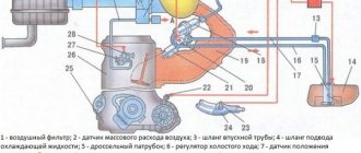
1. Generator device connection diagram
2. Contactless ignition system
Ignition circuit for VAZ 2108
VAZ 2108 vehicles use a non-contact ignition system. There is no breaker in it, and the moment of sparking is controlled electronically. Below is its electrical diagram and a description of the main elements.
- Accumulator battery. Provides electrical current when starting the engine.
- Generator. Provides electric current when the car engine is running. In particular, it powers the ignition system.
- Fuse and relay mounting block. Serves for switching low voltage wires, in particular the ignition system.
- Ignition coil. Provides high voltage current to the ignition distributor.
- Switch. Provides a pulse for sparking (opening the power circuit of the primary winding of the ignition coil) in one or another cylinder according to a signal from the Hall sensor.
- Hall Sensor. Generates a control pulse (reducing voltage) for the switch, signaling the need for sparking in one or another engine cylinder.
- Ignition distributor (distributor) with vacuum and centrifugal ignition timing regulators. Serves to generate a control pulse to the switch (Hall sensor), distribute high voltage pulses across the spark plugs (“slider”), correct the ignition timing in accordance with the engine operating mode (centrifugal and vacuum regulators).
- High-voltage wires (armored wires). They serve to transmit high voltage current from the ignition coil to the distributor cover and then to the spark plugs.
- Egnition lock. Serves to close the ignition system circuit. Through it, electric current flows into the ignition system.
- Ignition relay. Serves to relieve the contacts of the ignition switch (lock) and supply voltage to the coil and switch.
- Spark plug. Serve to generate a spark in the engine cylinders.
One of the most important elements of the circuit is the photoelectric Hall sensor built into the ignition distributor. With its help, the BSZ (non-contact ignition system) fixes the position of the engine camshaft and determines the moment of spark formation.
When the car engine starts and during its further operation, the Hall sensor at the right times generates electrical impulses necessary for the formation of a spark at certain times. These pulses are then sent to an electronic switch, which amplifies them and transmits them to a high-voltage coil.