02/04/2022 15 408 VAZ 2107
Author: Ivan Baranov
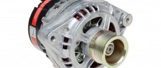
As with any car, the generator on the VAZ 2107 injector works in parallel with the battery - these are two power sources for the car, which are used in different modes. The article discusses the generator 37.3701, the principle of operation of the generator with different characteristics, including a maximum current of 80 Amperes, and provides instructions for connecting the unit. The G222 generator set is similar, you just need to pay attention to some differences.
[Hide]
Carburetor engines
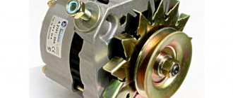
The connection diagram for the VAZ-2107 generator (carburetor and injector) depends on the year of manufacture of the car. The first carburetor models had a G-222 generator installed. The same device can be found on commercially produced VAZ-2105 and VAZ-2104 models with a carburetor injection system.
The maximum output current for such an installation is 55 amperes. But in recent years, cars with fuel injection systems have become widespread. Its use implies a large current consumption, so it is necessary to use a generator with a high current to ensure a normal charge level and power supply to all consumers.
How to test a generator using a light bulb and a multimeter
Checking the functionality of the generator is possible in several ways; for this you will need to use certain methods - this could be measuring the output current of the generator, the voltage drop on the wires connecting the current output of the generator to the battery, or checking the regulated voltage.
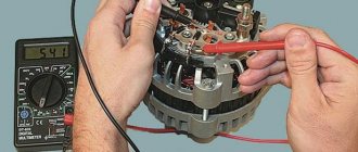
For diagnostics, you will need a multimeter, a battery and a light bulb with wires soldered to its contacts, wires to connect the generator to the battery, and you can also take a drill with a specific head - it may be needed to rotate the rotor through the pulley nut.
The connection diagram is as follows: output terminal “B+” and rotor D+. The lamp fits between the generator output and the D+ contact. Then the power wires connect the negative on the battery to the generator ground. “Plus” from the battery, respectively, with the plus of the generator and the B+ terminal. The structure is securely fixed in a vice and connected.
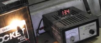
The multimeter is switched to DC voltage measurement mode, one probe is connected to the “plus” of the battery, and the second to the “minus”. If everything is in order, the lamp will light up, and the voltage should be 12.4 volts.
Then, use a drill to spin the generator. At this moment, the lamp should go out and the voltage should rise to 14.9 V. Then a load is added - for this purpose you can use an H4 halogen lamp. It is also hung on the battery terminals, after which it should light up.
Next, the generator is turned again with a drill. The voltmeter should record a voltage of 13.9 volts. Without a drill, the battery should produce approximately 12.2 volts. If this does not happen or the readings are very different, then the generator is faulty.
Injection engines
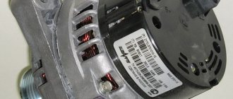
On injection engines, generator sets 5142.3771 or similar are used. They have increased energy, the maximum current is about 80-90 A, it all depends on the design option. Cars of the seventh series and similar models are good because they are like a designer set. You can install almost any generator on them, similar in design to the “native” one.
For tuning, installations with an output current of 100 amperes and higher are used. But the use of such devices is justified only if many powerful consumers are connected to the electrical equipment. Regardless of the design, the generators produce alternating current; a voltage regulator, capacitor and diode block are installed in the housing.
How to excite a gene
So, what needs to be done to excite the generator? As mentioned above, the tablet should be removed from the generator, since the malfunction arose precisely there. Next, connect the positive terminals of both devices, and cut the negative terminal in the chocolate bar. During the assembly process, connect it to a mass of brushes.
Insulate the wire from terminal “30” of the gene, connect an indicator with a power of no more than 15 W to the output circuit “15”. This applies to the genes of the G222 series. If the units are of other models, then they must be excited by connecting the indicator to terminal “B”.
Self-excitation of a generator can be imagined this way.
In the diagram above, the leftmost arrows indicate diodes. They are installed only in generators of modern models; they do not exist in older units. More precisely, the circuit without the presented diodes is considered classic, and with them - modernized, modern.
In some gene models, the anchors imply the presence of brushes. They are also removed and the tablet is drilled out. One contact goes directly to the armature through the diodes to the plus, as can be seen in the diagram, the second contact goes to the minus (lowest arrow).
Accordingly, the diagram shows: plus and minus.
The current will not begin to flow immediately, that is, not at low speeds. Somewhere, if you look at the tachometer, voltage will begin to be generated after 4000 rpm. In other words, we rev up to 4 thousand rpm and current appears. If we go down to 1 thousand rpm or less, the voltage disappears and we will need to rev the throttle again. This is approximately the principle of current generation during self-excitation.
Some cars have a low-speed engine. In this case, you will have to do something with the pulleys to increase the initial rotation speed. For a normal engine everything should be fine.
Go ahead. The output is not 12 volts, you should know this from the beginning. Without a regulator, the gene will output whatever it can, up to 20-30 volts. For example, during start it reaches 36 volts. This can be checked by using a light bulb of this voltage connected to the outputs. Then it drops to 20 volts.
The scheme can certainly be improved. For example, embed a capacitor into the positive wire going to the armature. This is done in order to prevent a drop in voltage when the engine speed drops. A good capacitor can also be placed at the output to smooth out the first voltage surge and regulate and smooth out dips.
When implementing this circuit, it is important to remember about delivering high voltage. This is not 12 volts, you can easily burn out light bulbs, the ECU and basically all the car electrics.
Warning. In self-excitation mode, the gene will give everything it can without any restrictions, which is fraught with overheating for itself. A little more load, and write a eulogy to the generating device. Therefore, this method is applicable only as a necessary measure, again, if you are left on the road and need to get to the nearest service station.
Forget about fines from cameras! An absolutely legal new product - Traffic Police Camera Jammer, hides your license plates from the cameras that are installed in all cities. More details at the link.
Cars before 1986
The G-222 generator was used in cars. The connection diagram for the VAZ-2107 is almost the same as on later models. But there are features, among the main ones - there is a control lamp indicating battery charging. Moreover, it worked using an electromagnetic relay.
When the ignition is turned on, power is supplied from the lock through the instrument panel fuse to the electromagnetic relay of the battery charge lamp and the coil contact. The second contact of the coil is connected to the center wire on the generator (the point where the three windings connect).
The electromagnetic relay has normally closed contacts, so when the ignition is turned on, the lamp lights up. But as soon as the engine starts running, the generator produces current. And a current flows through the control lamp coil, which causes the armature to attract and open the contacts.
At the same time, the power to the incandescent lamp stops and it goes out. This indicates that the battery is charging normally. Only when the power supply to the lamp stops will voltage be applied to the excitation winding and the generator will be able to return to operating mode.
Additional resistors that work in conjunction with the light bulb
Some circuits use useful additional resistors that are located in the instrument panel, in the same place as the light bulb.
Resistor R 1 is connected in parallel with the light bulb; if the light bulb burns out, the generator will still work because the initial excitation current will flow through this resistor. Resistor R2 is needed if the rotor or brushes break, the generator immediately stops working, and the light should light up, indicating that there is no charging, but in this case the light will not light up because the circuit is broken. If there is a resistor R2, it diverts the light bulb current to ground and it will light up, because the plus is on the additional side. diodes will disappear.
1200 rub. for the photo report
We pay for photo reports on car repairs. Earnings from 10,000 rubles/month.
Write:
The most basic function of the generator is to charge the battery and power the electrical equipment of the engine.
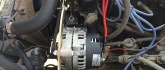
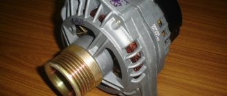
A generator is a mechanism that converts mechanical energy into electrical energy. The generator has a shaft on which a pulley is mounted, through which it receives rotation from the engine crankshaft.
Interactive image of the generator circuit. Works on mouseover
A car generator is used to power electrical consumers, such as the ignition system, on-board computer, car lighting, diagnostic system, and it is also possible to charge a car battery. The power of a passenger car generator is approximately 1 kW. Car generators are quite reliable in operation because they ensure uninterrupted operation of many devices in the car, and therefore the requirements for them are appropriate.
Cars manufactured in 1996 and later (carburetor engines)
The connection diagram for the G222 generator on a VAZ-2107 after 1996 differs from the previous one in one small feature - the power supply to the excitation winding has been changed. Cars have been improved, and some improvements make it possible to kill two birds with one stone - simplify the design and make the fate of the driver easier.
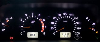
After 1996, instead of a warning lamp, they began to install a voltmeter, which more or less accurately shows the battery charge level. And if the lamp allows you to monitor only the presence or absence of voltage on the generator, then using a voltmeter the driver visually assesses the level. And if necessary, it can understand that repairs or maintenance are necessary.
Causes of breakdowns
Common causes of generator malfunctions are simple wear and corrosion. Almost all mechanical failures, be it worn brushes or collapsed bearings, are a consequence of long-term use. Modern generators are equipped with sealed (non-maintenance) bearings, which simply must be replaced after a certain period or mileage of the vehicle. The same applies to the electrical part - often the entire components must be replaced.
Also reasons may be:
- low quality components;
- violation of operating rules or operation outside normal operating conditions;
- external factors (salt, liquids, high temperature, road chemicals, dirt).
Generator circuit for injection engines
In fact, the design of the generator set is not much different from those installed on carburetor engines. Only the type of excitation and serviceability monitoring differ. The dashboard contains not only a warning lamp, but also a voltmeter; these two devices allow you to assess both the presence and level of charging. Current flows through the lamp filament and is supplied to the field winding when the engine starts. The connection diagram for the VAZ-2107 generator, regardless of the year of manufacture, implies operation in the following mode:
- When the ignition is turned on, power is supplied to the excitation winding. A magnetic field appears around the armature.
- When the crankshaft rotates with the starter, the generator armature also begins to move. With the help of movement and a magnetic field, a potential difference arises at the ends of the stator windings.
- From the windings, voltage (alternating, three-phase) is supplied to the rectifier unit, and from it to terminal “30” of the generator.
- Pin “30” is connected to the battery (positive terminal). Consequently, the entire electrical system is powered and the battery is charged.
In this case, the battery and generator G221A work in parallel. The connection diagram for the VAZ-2107 with carburetor and injection engines is almost identical, with only minor features.
Basic information about the excitation effect
ATTENTION! A completely simple way to reduce fuel consumption has been found! Don't believe me? An auto mechanic with 15 years of experience also didn’t believe it until he tried it. And now he saves 35,000 rubles a year on gasoline! Read more"
As is known, the voltage generated by the gene at different engine speeds is regulated by excitation windings. The current is maintained at a constant voltage - 13.8-14.2 V.
To provide the automotive system (numerous consumers) with current, a regulator or LV is provided. It can be found on domestic cars and some foreign cars; as a rule, it is built inside the generator. In everyday life, such a regulator is called a chocolate bar, a tablet, etc.
The gene is connected to the positive terminal of the battery through terminal “30”. It is also called plus, "B" or "BAT". As for the negative output, it is designated as “31” or minus. Also in everyday life there are other designations: “D”, “B-”, etc. The tablet terminal used to supply power from the vehicle network when the ignition is on - terminal “15” or “S”. Finally, the terminal designed to supply current to the charging test lamp is designated “61” or “D+”.
If the battery stops charging, this in most cases indicates damage to the chocolate bar. However, you shouldn’t despair here, because it will be enough to apply voltage to the windings, that is, to excite the generator in order to get to the store or the nearest service station.
So, in order to get to the right place without subjecting the battery to a deep discharge, you need to remove the chocolate bar and excite the gene.
Electrical diagram VAZ-2107 carburetor
Electrical diagram of VAZ 2107, 21074 produced in 1988-2001 with generator 37.3701
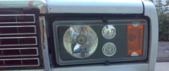
- block headlights
- side direction indicators
- accumulator battery
- starter relay
- carburetor electro-pneumatic valve
- carburetor microswitch
- generator 37.3701
- gearmotors for headlight cleaners *
- Fan motor switch sensor
- engine cooling fan motor
- sound signals
- distributor
- spark plug
- starter
- coolant temperature gauge sensor
- engine compartment lamp
- low oil pressure warning sensor
- low brake fluid level indicator sensor
- windshield wiper motor
- carburetor electro-pneumatic valve control unit
- ignition coil
- headlight washer pump motor *
- windshield washer pump motor
- mounting block
- windshield wiper relay
- hazard warning and direction indicator relay
- brake light switch
- reverse light switch
- ignition relay
- ignition switch
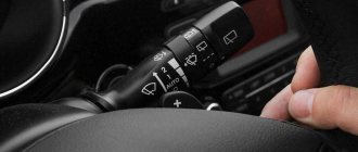
- three lever switch
- hazard switch
- socket for portable lamp**
- heater fan switch
- additional resistor for the electric motor of the heater (stove)
- rear window heating indicator lamp
- low brake fluid level warning lamp
- signaling unit
- heater fan electric motor
- glove compartment lamp
- light switches on the front door pillars
- switches for warning lights of open front doors ***
- front door open warning lights ***
- connection block
- cigarette lighter
- watch
- instrument light switch
- diode for checking the serviceability of the low brake fluid level indicator lamp
- fuel level indicator
- fuel reserve indicator lamp
- speedometer
- turn signal indicator lamp
- carburetor choke indicator lamp
- battery charge indicator lamp
- carburetor choke warning switch
- instrument cluster
- econometrician
- light switches on the rear door pillars
- coolant temperature gauge
- tachometer
- parking brake indicator lamp ("handbrake")
- low oil pressure warning lamp
- high beam indicator lamp
- indicator lamp for turning on external lighting
- voltmeter
- parking brake indicator switch ("handbrake")
- outdoor light switch
- rear window heating switch with backlight
- rear fog light switch with on/off indicator *
- fog light circuit fuse
- lampshade ****
- tail lights
- level indicator and fuel reserve sensor
- connectors for connecting to the rear window heating element *
- license plate lights 2107
Wiring diagram VAZ-2107 carburetor - full view:
Troubleshooting battery failure
The first step is to check the tension of the alternator belt - it is what drives the alternator and coolant pump, so this malfunction can also manifest itself as engine overheating.
If the VAZ 2107 battery charging lamp does not light up, and the voltmeter shows the normal voltage of the on-board network and the battery does not charge, the reason is obviously in the contacts at the terminals.
You need to remove the terminals from the battery and clean them with sandpaper. If charging does not appear, it is necessary to measure the voltage at output “30” of the generator with the engine running. If the voltage readings at this output and the battery are very different, you need to clean the contacts and check the wire running from the generator to the battery. If the wire is faulty, it must be replaced.
Another reason for the lack of charging may be a short circuit or break in the stator or rotor winding, as well as a broken rectifier diode on the generator.
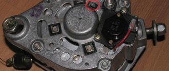
Diodes can be checked using a test lamp or multimeter. A multimeter is used to check the resistance of the diodes. To check the diodes using a test lamp, you need to remove the “+” terminal from the battery and connect the test lamp with one end to the positive terminal, and with the other you need to sequentially touch the three bolts shown in the figure below. Then do the same operation, only with the “-” terminal. If the control lamp lights up, then the diode being tested is broken.
If one of the diodes fails, it is necessary to replace the diode bridge assembly.
A malfunction of the stator winding can be determined with a multimeter by measuring the resistance between the rectifier unit mounting bolts. If there is no contact between them, then there is a winding break. In this case, the winding or generator assembly is changed.
Probably the most common cause of generator failure is brush wear. To check them, you need to remove the brush assembly. The length of the brushes must be more than 5 mm, otherwise they need to be replaced. Brushes can also become jammed or skewed in the wells.
Mounting block connection diagram
P1 — relay for turning on the heated rear window; P2 - relay for turning on the headlight cleaners and washer; P3 - relay for turning on sound signals; P4 - relay for switching on the electric motor of the engine cooling system fan; P5 - headlight high beam relay; P6 - low beam headlight relay; A - the order of conditional numbering of plugs in the mounting block blocks. The outer number with the letter “Ш” in the plug designation is the block number, and the inner number is the conventional number of the plug.
Schemes of individual blocks of the seven
Power supply system
Power plant starting system
1 - starter; 2 - relay; 3 — ignition switch; 4 - battery
Ignition system
1 - generator; 2 — ignition switch; 3 - distributor; 4 - breaker; 5 — candles; 6 - coil; 7 - battery
Contactless ignition system
External and internal lighting
Windshield wipers and washers
1 — electric motors of the windshield wiper; 2 — washer motor; 3 — mounting block; 4 — ignition switch; 5 - washer switch
Cooling Fan
1 — fan electric motor; 2 - sensor; 3 — mounting block; 4 - ignition relay; 5 - ignition switch.
Common battery problems:
- short circuit of battery electrodes/plates;
- mechanical or chemical damage to the battery plates;
- violation of the tightness of battery cans - cracks in the battery case as a result of impacts or improper installation;
- chemical oxidation of the battery terminals. The main causes of these malfunctions are:
- gross violations of operating rules;
- expiration of the product's service life;
- various manufacturing defects.
Wires for connecting electrical appliances
| Connection type | Section, mm 2 | Insulation color |
| Negative terminal of the battery - vehicle ground (body, engine) | 16 | Black |
| Starter positive terminal - battery | 16 | Red |
| Positive contact of the generator - plus battery | 6 | Black |
| Generator - black connector | 6 | Black |
| Terminal on the generator “30” – white MB block | 4 | Pink |
| Starter connector “50” – starter relay | 4 | Red |
| Starter Start Relay - Black Connector | 4 | Brown |
| Ignition switch relay - black connector | 4 | Blue |
| Ignition switch output “50” – blue connector | 4 | Red |
| Ignition switch connector “30” – green connector | 4 | Pink |
| Right headlight plug - ground | 2,5 | Black |
| Left headlight plug - blue connector | 2,5 | Green, gray |
| Generator output “15” – yellow connector | 2,5 | Orange |
| Right headlight connector - ground | 2,5 | Black |
| Left headlight connector - white connector | 2,5 | Green |
| Radiator fan - ground | 2,5 | Black |
| Radiator Fan - Red Connector | 2,5 | Blue |
| Ignition switch output “30/1” – ignition switch relay | 2,5 | Brown |
| Ignition switch contact “15” – single-pin connector | 2,5 | Blue |
| Right headlight - black connector | 2,5 | Grey |
| Ignition switch connector “INT” – black connector | 2,5 | Black |
| Six-pin block of the steering column switch - “ground” | 2,5 | Black |
| Two-pin block of the steering column switch - glove box illumination lamp | 1,5 | Black |
| Glove compartment light - cigarette lighter | 1,5 | Black |
| Cigarette lighter - blue block connector | 1,5 | Blue, red |
| Rear window defroster - white connector | 1,5 | Grey |
FakeHeader
Comments 16
My brain explodes at the end of the article! Maybe I didn’t understand correctly, but from what I read I concluded that from the generator, namely, from the brushes, we throw the wire to the relay on pin 67, and from pin 15 we throw the wire again on the generator, namely on the M8 threaded stud, where 2 thick wires. So? Did I understand everything correctly?
So, here it would be necessary to be more precise. if you have a wire from the brushes going to the diode bridge, then you need 67 from the brushes and 15 to the wire that was inserted into the brushes. if not, then the wire comes from the brushes at 67 and 15 goes to that pin. But in this and in the case that the wire is a pin, this is the + output.
In general, I have an Oda and it has a VAZ2105 type generator with a tablet in the generator on the brushes, I bought myself a generator from a VAZ 2101 and now I’m looking for information on how to connect it. I have only 2 wires coming from my original generator, one double, on the M8 stud, the other to the terminal on the generator, and now a terminal has formed from the brushes, that’s the question, that’s why I’m asking how to properly connect with an external relay. I myself am not an electrician, for me these are murky miracles))) That is, as I understand it, we loop the relay on the generator from brushes 67 and from 15 to the M8 pin, leaving everything else unchanged? I looked at the diagram in the article, where the wire from the gene goes to 67 in the relay, and from 15 to the fuse block, here I am in a stupor... firstly, where to connect in the block, and secondly, the option with a loop confused me, because . It turns out 2 different connection options.
Car wiring diagram
1 – radiator fan drive motor; 2 – relay and fuse block (mounting block); idle speed sensor; 4 – engine control unit; 5 – potentiometer; 6 – set of spark plugs; 7 – ignition control unit; 8 – electronic crankshaft sensor; 9 – electric fuel pump; 10 – tachometer 2107; 11 – lamp for monitoring the health of electronic systems; 12 – ignition system control relay; 13 – speed sensor; 14 – diagnostic connector; 15 – set of injectors; 16 – adsorber solenoid valve; 17, 18, 19 – fuse block protecting the injection system circuits; 21 – electronic fuel pump control relay; 22 – electronic relay for controlling the intake pipe heating system; 23 – intake pipe heating system; 24 – fuse protecting the heater circuit; 25 – electronic oxygen level sensor; 26 – cooling system temperature control sensor; 27 – electronic air damper sensor; 28 – air temperature sensor; 29 – pressure control sensor.
Fuse and relay diagram 2107
On newer “sevens” a block with 17 fuses and 6 relays is installed. VAZ 2107 fuses on the “new” unit protect the following electrical circuits and devices:
- Reversing lamps, heater fan, rear window defroster warning lamp and relay, rear wiper motor and rear washer pump.
- Electric motor for front wipers.
- Reserve socket.
- Reserve socket.
- Power supply for heated rear window.
- Clock, cigarette lighter, power socket “carrying”.
- Signal and radiator fan.
- Turn signal lamps in emergency mode.
- “Fog lights” and a relay that regulates the voltage of the on-board network.
- Instrument panel lamps.
- Brake light bulbs.
- Right high beam headlight.
- Left high beam headlight, high beam warning lamp.
- Side lights (rear right, front left), license plate and engine compartment lighting.
- Side lights (rear left, front right), glove compartment and cigarette lighter lamps.
- Low beam (right lamp).
- Low beam (left lamp).
The block relays perform the following functions:
- Heated rear window relay.
- Headlight cleaner and washer relay.
- Signal relay.
- Cooling system electric fan relay.
- High beam relay.
- Low beam relay.
The fuse block of the VAZ 2107 (injector) is no different from the block on the carburetor “seven”. Injection models are simply equipped with an additional relay and fuse box installed in the cabin under the glove compartment. The block includes three relays - the “main” relay, the fuel pump relay and the fan relay.
Troubleshooting
On modern cars, using the “old-fashioned” diagnostic method by removing it from the battery terminal can lead to serious damage to many of the car’s electronic systems. Significant voltage drops in the vehicle's on-board network can damage almost all on-board electronics. That is why modern generators are always checked only by measuring the voltage in the network or diagnosing the removed unit itself on a special stand. First, the voltage at the battery terminals is measured, the engine is started, and readings are taken while the engine is running. Before starting, the voltage should be about 12 V, after starting - from 13.8 to 14.7 V. A deviation towards the higher side indicates that you are “overcharging”, which implies a malfunction of the relay regulator, towards a lower level - that no current is flowing. The absence of recharging current indicates a malfunction of the generator or circuits.