There were problems with the generator, it wouldn’t charge me, this article might help someone.
Technical characteristics of the generator Maximum output current (at 13 V and 6000 min), A...80 Adjustable voltage limits, V...13.2-14.7 Gear ratio engine - generator...2.4
Features of the design of the VAZ 2110, VAZ 2111, VAZ 2112 generator Generator type 94.3701 - alternating current, three-phase, with a built-in rectifier unit and an electronic voltage regulator, right-hand rotation (on the drive side). Some cars of the VAZ 2110 family can be equipped with an AAK-5102 generator made in Slovenia. In terms of its characteristics and installation dimensions, this generator is interchangeable with the 94.3701 generator, but has some differences in the design of components and parts. This chapter describes only the 94.3701 generator. Stator 10 (Fig. 7-5) and covers 9 and 11 are tightened with four screws. The rotor shaft 16 rotates in bearings 3 and 13, which are installed in the covers. Power is supplied to the rotor winding (excitation winding) through brushes and slip rings 4. The three-phase alternating current induced in the stator winding is converted into direct current by a rectifier unit 1 attached to the cover 9. The electronic voltage regulator 7 is combined into one unit with a brush holder and is attached also to cover 9. The generator connection diagram is shown in Fig. 7-6. The voltage to excite the generator when the ignition is turned on is supplied to terminal “D+” of the regulator (terminal “D” of the generator) through a control lamp located in instrument cluster 5. After starting the engine, the excitation winding is powered by three additional diodes installed on the rectifier block of the generator. The “W” output of the generator is not used on cars of the VAZ 2110 family. The operation of the generator is controlled by a warning lamp in the instrument cluster. When the ignition is turned on, the lamp should be on, and after starting the engine it should go out if the generator is working. If the lamp burns brightly or glows at full intensity, it indicates a malfunction
rice. 7-5. Generator94.3701: 1 - rectifier unit; 2 — bearing sleeve; 3 — rear bearing of the rotor shaft; 4 — slip rings; 5 — output “B+” of the generator; 6 - casing; 7 — voltage regulator with brush holder; 8 — coupling screw; 9 — back cover; 10 - stator; 11 — front cover; 12 — spacer ring; 13 — front bearing; 14 - pulley; 15 — washer; 16 - rotor
rice. 7-6. Generator system connection diagram: 1 - battery; 2 - generator; 3 — mounting block; 4 — ignition switch; 6 - battery charge indicator lamp, located in the instrument cluster
Warnings: The negative of the battery must always be connected to ground, and the positive must be connected to the B+ terminal of the generator. Failure to turn the battery back on will immediately cause increased current through the generator valves and damage them. It is not allowed to operate the generator with the battery disconnected. This will cause the occurrence of short-term overvoltages at the B+ terminal of the generator, which can damage the generator voltage regulator and electronic devices in the on-board network of the VAZ 2110, VAZ 2111, VAZ 2112. It is prohibited to test the generator’s functionality “for spark” even by briefly connecting the “B+” terminal generator with 'mass'. In this case, significant current flows through the valves and they are damaged. The generator can only be checked using an ammeter and voltmeter. The generator valves are not allowed to be checked with a voltage of more than 12 V or with a megger, since it has a voltage too high for the valves and they will be broken during testing (a short circuit will occur). It is prohibited to check the vehicle's electrical wiring with a megger or a lamp powered by a voltage of more than 12 V. If such a check is necessary, you must first disconnect the wires from the generator. The insulation resistance of the generator stator winding with increased voltage should be checked only on a stand and always with the terminals of the phase windings disconnected from the valves. When electrically welding components and parts of the car body, you should disconnect the wires from all terminals of the generator and battery.
Possible malfunctions of the generator VAZ 2110, VAZ 2111, VAZ 2112, their causes and methods of elimination Cause of malfunction Method of elimination The warning lamp does not light up when the ignition is turned on The control devices do not work 1. Fuse F19 has blown in the mounting block 2. An open circuit in the power supply circuit of the instrument cluster: not voltage is supplied from the mounting block to the instrument cluster; no voltage is supplied from the ignition switch to mounting block 3. The ignition switch does not operate
1. Replace fuse 2. Do the following: check wire “O” and its connections from the mounting block to the instrument cluster; check the “GP” wire and its connections from the ignition switch to the mounting block 3. Check, replace the faulty contact part of the ignition switch The warning lamp does not light up when the ignition is turned on and does not light up when the engine is running The control devices are working The battery is discharged 1. The warning lamp is burnt out or insufficient pressing the lamp socket contacts to the printed circuit board 2. Open circuit between the instrument cluster and plug “D” of the generator 3. Worn or stuck brushes, oxidation of slip rings
4. The voltage regulator is damaged (break between the “DF” terminal and the “ground”) 5. The wire from the “D+” terminal of the brush holder is disconnected 6. Short circuit in the positive valves 7. Unsoldering the excitation winding terminals from the slip rings 1. Replace the burnt-out test lamp, bend the contacts of the lamp socket or replace it 2. Check the “KB” wire and its connections from the generator to the instrument cluster 3. Replace the brush holder with brushes, wipe the rings with a napkin soaked in gasoline 4. Replace the voltage regulator
5. Connect the wire 6. Replace the rectifier unit 7. Solder the leads or replace the generator rotor The control lamp is bright or glows at full intensity when the engine is running The battery is discharged 1. The generator drive belt is slipping 2. The voltage regulator is damaged 3. The valves of the rectifier unit are damaged 4. The field winding power diodes are damaged 5. Disconnection of the field winding leads from the slip rings 6. Open circuit or short circuit in the stator winding, shorting it to ground 1. Adjust the belt tension 2. Replace the voltage regulator 3. Replace the rectifier unit 4. Replace the diodes or rectifier unit 5. Solder the leads or replace the generator rotor 6. Replace the generator stator
Principle of operation
The principle of operation is this: you turn the key in the lock, and current flows to the excitation wire. The magnetic field that the armature creates penetrates the stator windings, at the terminals of which voltage appears. When the armature reaches a sufficiently high rotation speed, which is provided by the pulley and belt drive, the so-called self-excitation mode occurs.
The rectifier unit converts alternating current into direct current. The voltage regulator starts working when the crankshaft speed changes (accordingly, the armature rotates faster or slower) and regulates the time for which the field wire is turned on. Sometimes a generator malfunction may occur due to a blown fuse in the circuit.
Types of car generators
Generators have been developed for vehicles that produce direct and alternating current. The first vehicles were completed until 1960. At the moment, they have been completely replaced by more modern, reliable ones that provide constant current thanks to semiconductor rectifiers.
DC generator
These units met the requirements for vehicles until the early sixties. The electromagnets in them are stationary, the EMF (electromotive force) is in the rotor, the voltage on the brushes is of the same polarity, the current is removed from the half rings insulated from each other.
There are 3 types of these electric generators:
- with a winding connected to the battery;
- with parallel excitation (shunt circuit);
- with a series circuit for connecting the stator and armature windings.
Due to the ability to act as a motor if current is supplied to the armature, modern DC electric generators are installed in hybrid vehicles.
Progress in the production of cars with internal combustion engines required higher power, optimization of technical characteristics, reduction in size, and long service life.
DC equipment has many disadvantages:
- low power;
- low efficiency;
- inconvenient connection diagram;
- large dimensions and weight;
- frequent maintenance;
- need for constant monitoring
DC equipment was used for the longest time on the railway, but over time it was replaced by three-phase AC units.
Alternator
A lot of time has been spent developing compact, powerful, durable electric generators for cars. The new equipment is relatively lightweight, the starting speed is reduced, reliability is increased, the service life is longer, and maintenance costs are lower.
Functions performed
So, what is a generator for? First of all, in order to provide all VAZ 2110 equipment that runs on electricity with energy. Perhaps someone thinks that this is the battery's task. Not really, because the battery is needed to maintain functionality when the engine is not running (it starts the engine, supports the alarm, music system while parked, etc.).
But when the engine has already started, with the help of the battery, the generator comes into play. During the trip, it is he who supports the operation of all electronics, air conditioning, audio (or even video systems), and everything else that you have added to your VAZ 2110.
Another equally important function of the generator is charging the battery. This also happens when the engine is running. And if it weren’t for this device, the battery would not be able to cope with its tasks, and it would have to be charged all the time.
Considering that today on the VAZ 2110, in addition to the standard layout, many additional energy consumers are installed, it happens that the generator voltage is not enough. In this case, it makes sense to install a 120 amp generator.
Specifications
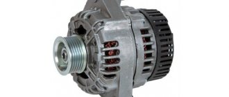
Most often, the VAZ 2110 is equipped with a Katek generator, usually designated by the numbers 5102.3771, but it can also be 94.3701. Both generators have a power of 80 amperes, and the output voltage is about 14V. But recently Katek has been releasing a new type of generator, also suitable for the VAZ 2110.
It produces a current of up to 120 amperes, and is more suitable for the high energy loads of a modern car. By installing a 120-amp generator, you can ensure simultaneous uninterrupted operation of almost all electricity consumers.
Device components
If the generator device is considered in terms of size, then there are compact and traditional ones. They also differ in their design features.
- drive pulley;
- excitation wire;
- bracket;
- anchor device.
They can be fastened with one bolt, or with several, and other “little things”. However, any generator has a general structure.
- The rotor (or armature) is the rotating part of the generator. The armature is designed to create a magnetic field using an excitation winding located on the shaft. The excitation wire is powered by slip rings located on the same shaft. The following are also located here: the excitation winding wire, the fan impellers (one or two), the drive pulley and the bearing assembly;
- The stator is the stationary part of the generator, consisting of three windings (three-phase), which create alternating current. These windings can be connected to each other by the so-called “star” or “delta”;
- The housing is most often made of lightweight non-magnetic aluminum alloy; it consists of two covers, secured with a bolt. The front cover is located in the same place as the drive pulley; the back cover is on the side where the slip rings are. Each bolt that connects the back and front covers is tightened. In the future, to disassemble the generator on a VAZ 2110, it is enough to remove the bolt mounts;
- Mounting the generator on a VAZ 2110. There is an upper mounting bracket that uses 2 bolts. The lower mounting bracket most often has one bolt, but there may be two, in which case minor modifications may be necessary. The bolt can be anything, the main thing is that the size is suitable, sometimes a sleeve is required for this. It is better not to redo the bracket itself. The bracket securely holds the generator, which has many responsibilities. And yet, we should not forget that the bracket, like the bolt, can break, so you need to monitor its condition;
- The structure of the brush assembly consists of two graphite brushes, springs that press them, and a brush holder;
- In modern Katek generators, the voltage wire and brush holder are located together in a non-separable unit. Therefore, if the voltage regulator fails, the entire assembly must be replaced. Structurally, this regulator can have a hybrid device - when radio elements with electronic devices are in the same circuit. But an integral is when the regulator is made in thin-film microelectronics technology. Many believe that the integral regulator copes better with its mission - controlling the duration and frequency of current pulses. The regulator changes the voltage used to charge the battery. At higher temperatures, less voltage goes to the battery. Although, in principle, it is not so important whether the integral is responsible for this regulation, or the hybrid;
- A rectifier unit with six diodes is responsible for converting the alternating current generated by the armature and stator into direct current, directly used by all on-board equipment. It also serves to charge the battery;
- The device is driven by a belt drive. It provides a significant increase in the speed at which the crankshaft rotates. In this case, the V-belt wears out faster if the pulley has a small diameter. If the driven pulley is small, it is better suited to a serpentine drive, which is more often used in modern generators.
Regulations
Taking into account the large number of electrical elements, a number of normative documents have been developed for their alphanumeric (hereinafter referred to as BO) and conventional graphic designations (UGO) to eliminate discrepancies. Below is a table showing the main standards.
Table 1. Standards for graphic designation of individual elements in installation and circuit diagrams.
| GOST number | Short description |
| 2.710 81 | This document contains GOST requirements for BO of various types of electrical elements, including electrical appliances. |
| 2.747 68 | Requirements for the dimensions of displaying elements in graphical form. |
| 21.614 88 | Accepted codes for electrical and wiring plans. |
| 2.755 87 | Display of switching devices and contact connections on diagrams |
| 2.756 76 | Standards for sensing parts of electromechanical equipment. |
| 2.709 89 | This standard regulates the standards in accordance with which contact connections and wires are indicated on diagrams. |
| 21.404 85 | Schematic symbols for equipment used in automation systems |
It should be taken into account that the element base changes over time, and accordingly changes are made to regulatory documents, although this process is more inert. Let's give a simple example: RCDs and automatic circuit breakers have been widely used in Russia for more than a decade, but there is still no single standard according to GOST 2.755-87 for these devices, unlike circuit breakers. It is quite possible that this issue will be resolved in the near future. To keep abreast of such innovations, professionals monitor changes in regulatory documents; amateurs do not have to do this; it is enough to know the decoding of the main symbols.
What to choose?
In terms of popularity and reliability, the first places are occupied by manufacturers Bosch (Bosch), Denso (Denso) and Delphi (Delphi). But you should know that Katek (KZATE) (made by us) are also quite reliable and do a good job of their duties on the VAZ 2110, creating the required voltage. Maybe somewhere they lose against Bosch, but compared to the Chinese they are at their best.
VAZ generators of the tenth family:
So it’s difficult to say for sure which generator is right for you; the best one is the one that provides the necessary power to operate electrical appliances and charge the battery. If we take the advantages that Katek clearly has, then this is sufficient reliability, and also - what is important - the availability of inexpensive spare parts for sale: you can always buy at least a fuse, a pulley, an armature, a voltage regulator, an excitation wire, etc.
A car generator is a mandatory element of the on-board network of any modern car, regardless of the type of engine and the fuel it consumes. It is he who provides energy to all systems and mechanisms that consume electric current.
In this article we will look at the design, technical characteristics and operating principle of the VAZ-2110 generator. In addition, we will talk about its malfunctions, diagnostic methods and troubleshooting methods.
Design Features
The stator core has a cylindrical shape. A three-phase winding is wound on it according to a star circuit, the ends of which are brought out to the rectifier block. The stator is protected from above by a housing consisting of two covers fastened together with four bolts. There is an anchor inside it. It is mounted on two ball bearings. Their purpose is to ensure uniform rotation of the shaft.
At the rear of the generator there is a rectifier module consisting of six diodes, as well as a voltage regulator with a brush holder and brushes. For protection purposes, these elements are covered with a steel casing.
Principle of operation
In order for the generator to supply current to the load, the field winding must be energized. This, in fact, happens when we turn on the ignition. Next, the crankshaft of a running engine causes the armature to rotate. At this time, electricity begins to be generated in the stator winding, which is sent to the on-board network.
In VAZ-2110 cars, the generator produces alternating current, and all consumers are designed for direct current. To convert it, a rectifying diode unit is used.
But that's not all. The fact is that the voltage produced by the generator constantly changes depending on the number of crankshaft revolutions. To stabilize it, a voltage regulator relay is used.
As a result, at the terminals of the device we have a constant electric current of stable voltage.
Generator system diagram
Visual diagram of generator circuit connections
1 – battery; 2 – generator; 3 – mounting block; 4 – ignition switch; 5 – battery charge indicator lamp, located in the instrument cluster
- The “minus” of the battery should always be connected to ground, and the “plus” should always be connected to the “B+” terminal of the generator. Failure to turn the battery back on will immediately cause increased current through the generator valves and they will fail.
- It is not allowed to operate the generator with the battery disconnected. This will cause short-term overvoltages to occur at the “B+” terminal of the generator, which can damage the generator voltage regulator and electronic devices in the vehicle’s on-board network.
- It is prohibited to check the functionality of the generator “for spark” even by briefly connecting the “B+” terminal of the generator to “ground”. In this case, a significant current flows through the valves, and they fail. The generator can only be checked using an ammeter and voltmeter.
- The generator valves are not allowed to be checked with a voltage of more than 12 V or with a megger, since it has a voltage too high for the valves and they will be broken during testing (a short circuit will occur).
- It is prohibited to check the vehicle's electrical wiring with a megger or a lamp powered by a voltage of more than 12 V. If such a check is necessary, you must first disconnect the wires from the generator.
- The insulation resistance of the generator stator winding with increased voltage should be checked only on a stand and always with the terminals of the phase windings disconnected from the valves.
- When electrically welding components and parts of the car body, you should disconnect the wires from all terminals of the generator and battery.
Generator type 94.3701 – alternating current, three-phase, with built-in rectifier unit and electronic voltage regulator, right rotation (drive side).
An AAK-5102 generator made in Slovenia can be installed on some vehicles. In terms of its characteristics and installation dimensions, this generator is interchangeable with the 94.3701 generator, but has some differences in the design of components and parts. This chapter describes the 94.3701 generator.
The stator and covers 10 and 11 (Fig. Generator 94.3701) are tightened with four screws. The rotor shaft 19 rotates in bearings 20 and 25, which are installed in the covers. Power is supplied to the rotor winding (excitation winding) through brushes and slip rings 27.
The three-phase alternating current induced in the stator winding is converted into direct current by a rectifier unit attached to the cover 10. The electronic voltage regulator 8 is combined into one unit with a brush holder and is also attached to the cover 10.
The generator connection diagram is shown in Fig. Generator system connection diagram. The voltage to excite the generator when the ignition is turned on is supplied to terminal “D+” of the regulator (terminal “D” of the generator) through indicator lamp 5 located in the instrument cluster. When the ignition is turned on, the lamp should be on, and after starting the engine, it should go out if the generator is working. A brightly burning lamp or glowing at full intensity indicates a malfunction.
After starting the engine, the excitation winding is powered by three additional diodes installed on the generator rectifier block.
The “W” output of the generator is not used on vehicles of the VAZ-2110 family.
Technical characteristics of generator type 94.3701:
— maximum output current at 13 V and 6000 rpm, A: 80 — regulated voltage limits, V: 13.2–14.7 — motor-generator gear ratio: 1:2.4 — capacitor capacity, μF: 2 .2±20%
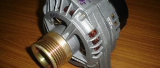
The generator is the basis for the functioning of the entire car. It can be compared to the human heart, since the generator is responsible for transporting electricity through all systems and components that depend on electricity. Mechanical energy is converted into electricity.
Like any other element of the machine, the VAZ 2110 generator has its own characteristics, functions, and operating principle. Today we will get to know him in as much detail as possible.
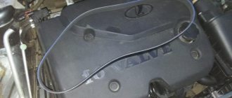
Appearance of the device
Malfunctions of the VAZ-2110 generator
Now let’s look at the breakdowns of the “tens” generator, which car owners have to deal with most often. These include:
- incorrect tension of the drive belt;
- bearing wear;
- failure of the rectifier unit;
- malfunction of the voltage regulator relay;
- break (short circuit) of the rotor or stator windings.
Let's look at each of the faults in detail separately.
Troubleshooting algorithm
There is no need to think that charging is not happening for some very serious reason. Immediately check the condition of fuse F10, which is responsible for powering the excitation winding of the VAZ 2107 generator. But before doing this, it is better to make sure that the drive belt is intact and its tension is normal. But also pay attention to the fact that you cannot over-tighten it - there will be no recharging of the battery (provided that the regulator is operating in the intended mode), but the bearings will fail much faster.
If charging is not going well, the lamp, for example, burns at half intensity, then the fault must be looked for in the wiring. Namely, in the connections between the battery and the car body. Very often oxidation occurs, which prevents normal contact. Unscrew the nut, thoroughly clean the terminal and body surface, and then install the wire in place.
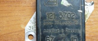
But if everything is fine with the switching, but charging still does not occur, you need to look further for the reason. And the first thing to suspect is the voltage regulator. With its help, the voltage at the generator output is stabilized. If this element fails, the battery overcharges or it does not charge well. Repair of this element is impossible, and the price in stores will be about 300 rubles. There are several options for regulators:
- A separate unit - installed on the body of a VAZ 2107 car.
- Combined with brushes - mounted directly in the generator.
How to check the regulator will be discussed in a separate article. If it is working properly, but charging still does not occur, or it is there, but it does not flow to the battery well, look for a fault in the brush assembly. It is quite possible that the wires that connect the brushes to the contacts have broken. But the most common thing is excessive wear or clogged brushes.
Somewhat less often, failure of the diode bridge or destruction of the stator or rotor windings occurs. To determine these breakdowns, you will need to completely disassemble the generator and carry out diagnostics using a tester and megger. Along the way, of course, it is best to replace the bearings in the VAZ 2107 generator.
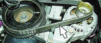
What's wrong with the belt
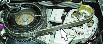
The VAZ-2110 generator belt serves as a drive for the rotor of the device. It transmits torque from the engine crankshaft to the armature pulley. The operation of the generator directly depends on its condition. An important point is belt tension. If it is loose, the pulley may slip. Because of this, the device will not be able to generate the current required parameters.
A sign of a loose belt is a characteristic “whistle”, which is more likely to occur in wet weather. The same symptoms indicate its wear and tear. Over-tensioning the belt distorts the rotor shaft. This contributes to accelerated wear of the device bearings.
The optimal belt tension is such that each of its fields in the middle between the pulleys can be shifted to the opposite side by a maximum of 15 mm.
How does it all work?
First you need to understand how everything works. So, on the VAZ-2107, the on-board network is powered from two sources - the battery and the generator. The first provides electricity to all consumers until the power plant is started. The battery itself is a storehouse of electrical charge, which it releases when needed.
A generator is a unit that generates electricity, but for this it is necessary that it perform a mechanical action (its rotor rotates). In order for the generator to operate and power the network, it is driven from the crankshaft via a belt drive.
Everything works simply: to start the engine, the battery energy is supplied to the power electric motor - the starter, as well as the ignition system. After the power plant starts, the generator will be driven by the drive, the generated energy of which will power all devices. It will also be supplied to the battery to restore the charge spent on starting the power plant.
Recharging the battery from the generator must be carried out without fail, otherwise after several starts of the power plant, the loss of electricity in the battery will be significant (the battery runs out), and it will simply not be able to start the engine.
Rectifier module
The rectifier module is designed to convert alternating current into direct current. It is based on six silicon diodes (gates): three positive and three negative. They are located on two horseshoe-shaped plates. To smooth out voltage surges, the terminals of the positive and negative diodes are connected through a 2.2 μF capacitor.
How to check the generator on a VAZ-2110 for the functionality of the rectifier unit with your own hands? To do this, you will need a regular car tester or test lamp. The essence of the test is based on the ability of diodes to pass current in only one direction. A faulty valve either does not pass current at all, or passes in both directions.
So, first you need to remove the casing of the rectifier unit. Next, connect the first wire of the test lamp to the “B+” terminal of the generator, and the second to the ground of the device. If the unit is working properly, the lamp should not light up. If it lights up, there is a short circuit in the rectifier and it needs to be replaced.
Don't be lazy to check the capacitor as well. Turn the tester into ohmmeter mode (1-10 MOhm) and measure its resistance. For a working capacitor, it should first take a minimum value and then gradually increase. If this does not happen, replace the capacitor.
Generator system diagram
Visual diagram of generator circuit connections
1 – battery; 2 – generator; 3 – mounting block; 4 – ignition switch; 5 – battery charge indicator lamp, located in the instrument cluster
- The “minus” of the battery should always be connected to ground, and the “plus” should always be connected to the “B+” terminal of the generator. Failure to turn the battery back on will immediately cause increased current through the generator valves and they will fail.
- It is not allowed to operate the generator with the battery disconnected. This will cause short-term overvoltages to occur at the “B+” terminal of the generator, which can damage the generator voltage regulator and electronic devices in the vehicle’s on-board network.
- It is prohibited to check the functionality of the generator “for spark” even by briefly connecting the “B+” terminal of the generator to “ground”. In this case, a significant current flows through the valves, and they fail. The generator can only be checked using an ammeter and voltmeter.
- The generator valves are not allowed to be checked with a voltage of more than 12 V or with a megger, since it has a voltage too high for the valves and they will be broken during testing (a short circuit will occur).
- It is prohibited to check the vehicle's electrical wiring with a megger or a lamp powered by a voltage of more than 12 V. If such a check is necessary, you must first disconnect the wires from the generator.
- The insulation resistance of the generator stator winding with increased voltage should be checked only on a stand and always with the terminals of the phase windings disconnected from the valves.
- When electrically welding components and parts of the car body, you should disconnect the wires from all terminals of the generator and battery.
Generator type 94.3701 – alternating current, three-phase, with built-in rectifier unit and electronic voltage regulator, right rotation (drive side).
An AAK-5102 generator made in Slovenia can be installed on some vehicles. In terms of its characteristics and installation dimensions, this generator is interchangeable with the 94.3701 generator, but has some differences in the design of components and parts. This chapter describes the 94.3701 generator.
The stator and covers 10 and 11 (Fig.) are tightened with four screws. The rotor shaft 19 rotates in bearings 20 and 25, which are installed in the covers. Power is supplied to the rotor winding (excitation winding) through brushes and slip rings 27.
The three-phase alternating current induced in the stator winding is converted into direct current by a rectifier unit attached to the cover 10. The electronic voltage regulator 8 is combined into one unit with a brush holder and is also attached to the cover 10.
The generator connection diagram is shown in Fig. . The voltage to excite the generator when the ignition is turned on is supplied to terminal “D+” of the regulator (terminal “D” of the generator) through indicator lamp 5 located in the instrument cluster. When the ignition is turned on, the lamp should be on, and after starting the engine, it should go out if the generator is working. A brightly burning lamp or glowing at full intensity indicates a malfunction.
After starting the engine, the excitation winding is powered by three additional diodes installed on the generator rectifier block.
The “W” output of the generator is not used on vehicles of the VAZ-2110 family.
Technical characteristics of generator type 94.3701:
— maximum output current at 13 V and 6000 rpm, A: 80 — regulated voltage limits, V: 13.2–14.7 — motor-generator gear ratio: 1:2.4 — capacitor capacity, μF: 2 .2±20%
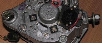
Voltage regulator
The regulator performs the function of a kind of stabilizer. Thanks to it, the voltage of the vehicle’s on-board network is the same, regardless of the number of revolutions of the running engine.
Essentially, a regulator is a relay that closes and opens a circuit. It happens like this. The voltage dropped below the required value, or rose above the norm - the relay disconnected the generator from the network. The voltage has reached the desired range - the regulator connected the device.
There are no electromechanical elements in the VAZ-2110 generator relay. It is built on semiconductors. In addition, its design also includes a brush holder with brushes. It is almost impossible to repair the regulator on your own. It's easier to replace it with a new one.
Checking the functionality of the relay takes no more than five minutes. Yes, and there is no need to disassemble anything here. The diagnostic procedure is as follows.
- We start the engine and warm it up to operating temperature.
- Turn on the low beam headlights and the heater fan.
- Using a tester turned on in voltmeter mode, we measure the voltage at the battery terminals.
The voltage should not go beyond 13.2 - 14.7 V. If it is higher or lower, the relay is faulty.
A regulator is considered faulty if its brushes are damaged or excessively worn. The minimum length of brushes is 5 mm.
What to do if the voltage relay fails?
It happens that the relay fails at the most inopportune moment, when you still have a drive home and the battery is not charging. The battery capacity in economical mode can ensure fairly long engine operation, which will allow you to get to the repair site without any problems. Below we will provide a list of recommendations that will help you drive, as they call it, “on battery power” and not stall.
- If the battery is overcharged, the relay must be disconnected from the circuit. To do this, the contact wires are removed from it and left hanging. In the case of the “ten”, it is enough to unplug the plug with the wire from the generator brush connector. Thus, battery charging is turned off, and further movement will no longer harm the battery.
- Many experts suggest going the other way - turning off the generator excitation winding. To do this, remove the corresponding fuse. However, this can be done if you know where the fuse is located.
- If the battery is weakly charged, then there is practically no reason to panic. To get to your destination, you need to maintain high speeds in order to, at least a little, bring the voltage value to the nominal value. Before stopping the engine, it is recommended to maintain the speed at 3000 rpm for a few seconds using the gas pedal. This will prepare the battery for the next start.
- Avoid using music, power windows, headlights (especially high beams), and other electrical devices unless their use is absolutely necessary. This will save battery power well.
Open circuit (short circuit) in the windings
In a VAZ-2110, the generator may also fail due to a break (short circuit) in the rotor or stator windings. Such a malfunction does not bode well, since it is almost impossible to eliminate it on your own. Here you will need to either rewind the windings or replace the faulty element (rotor or stator).
Before checking the generator on the VAZ-2110, it will need to be removed from the car and disassembled. Let's start with the stator. We take the tester, turn it on in ohmmeter mode and measure the resistance between each winding terminal and the housing. For a working stator it should tend to infinity. If the device shows less than 50 kOhm, there is a short circuit in the winding.
Let's move on to the rotor. Here it is necessary to measure the resistance between the slip rings. It should be within a few ohms. If the resistance is close to zero, the winding turns are closed. If the device produces too high readings, a break may occur.
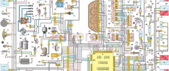
Battery charging circuit
The same scheme is used not only on the VAZ 2107; a similar one is used in any other car. The only difference is in the components - they are designed for different currents and operating modes. Charging circuit:
The circuit is not simple, it has a lot of elements that can fail. The contact may even break, causing the alternator to not charge the battery well. And all this affects your nerves - panic immediately begins.
1 - battery; 2 — Generator impeller; 3 - Protection diodes; 4 - Drive pulley; 5 - Rectifier diodes; 6 - Stator winding; 7 - Voltage regulator; 8 - Excitation winding; 9 - Filter capacitor; 10 - Fuse block; 11 - Indicator lamp on the dashboard; 12 - Voltmeter; 13 - Ignition switch relay; 14 - Ignition switch.
But there is no need to panic, it is enough just to diagnose the condition of all elements of the system. And even if you have an injector installed on a VAZ 2107, the car will be able to withstand the journey to the nearest service station or auto parts store. If the battery is in good condition, of course.
Do-it-yourself replacement of a VAZ-2110 generator
In some cases, it is not practical to repair the generator. The service life of the device declared by the manufacturer is 140 thousand km. If you are faced with a serious malfunction of the current-generating device in your "ten", estimate how much it will cost you to repair it, and compare it with the cost of a new generator. And it’s not that expensive – about five thousand rubles. But for this five thousand you will receive a new device with a guarantee, if used correctly, your car will drive for several years without any problems.
Replacing the VAZ-2110 generator can be done by hand. All that is required for this is an inspection hole, keys to “10” and “13”. The hole is needed to make it easier to get to the device mount. The replacement procedure is as follows.
- We place the car on the inspection hole, fix it, and remove the engine protection.
- Disconnect the negative terminal from the battery. Disconnect the wire from the generator that powers the rotor field winding (at the connector).
- Using a “10” wrench, unscrew the nut securing the “B+” output wires. We remove the wires.
- Loosen the adjusting screw and unscrew the fixing nut.
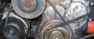
- Remove the drive belt.
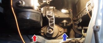
- Loosen the lower fastening of the VAZ-2110 generator (from the pit) by unscrewing the nut with a key set to “13”. We take out the fastening bolt.
- Remove the device (more convenient from below).
Installation of the VAZ-2110 generator is carried out in the reverse order. After replacement, be sure to properly tension the belt and connect the wires.
Some useful tips to extend the life of your generator
To ensure that your “ten” generator serves for a long time and does not present unpleasant surprises, use the following tips.
- At least once a month, check the condition of the device’s drive belt and its tension. If it is damaged, immediately take measures to replace it.
- Pay attention to the sound of the generator. If you hear a hum characteristic of failed bearings, replace them yourself, or contact a service center for this.
- Do not connect electrical appliances to the vehicle's on-board network that consume a current greater than the current generated by the generator.
- If the warning light on the instrument panel is constantly on, indicating that the battery is not charging, check the voltage regulator. If it fails, replace it.
- Do not expose the generator to water. It can cause a short circuit.
Diagnostics
Due to the fact that the price of a new generator is “biting”, and maintainability is quite high, many motorists do it themselves with their own hands to eliminate generator malfunctions in the VAZ 2110, which I suggest you do with the help of these instructions:
Fault No. 1
In the case when the control light on the instrument panel indicates a discharge of the battery, and when checking with a tester in the electrical circuit of the car, the voltage does not rise above 13.2 volts, it is necessary to check:
Checking the voltage in the on-board network
- Tension of the VAZ generator drive belt - tighten if necessary;
- If the rectifier block valve is damaged, replace the entire rectifier block;
- Diodes powering the exciting winding of the rotor - replacement of diodes or the entire rectifier block;
- The outputs of the exciting winding coming from the slip rings for their unsoldering - solder the outputs/replace the rotor or the entire generator assembly.
It is also possible that the stator winding may short-circuit, break or short circuit to ground (in this case, noise from the generator appears in the VAZ 2110, the generator “howls”). These assumptions are checked using an ohmmeter; if a malfunction is detected, the stator or the entire generator must be replaced.
Malfunction No. 2
The warning lamp in the instrument panel also indicates that the battery is low, and the tester displays a voltage value in the vehicle circuit of at least 14.7 volts:
- The voltage regulator has definitely failed (the contacts of the “DF” output have closed with ground) - replace the regulator.
Malfunction No. 3
The generator noise is clearly audible in the VAZ 2110:
- If sounds such as howling and squealing are heard. When disconnected, the wires remain, and when the drive belt is removed, they disappear, this means that the bearings have failed - replace the bearings (the front one is replaced as an assembly with a cover);
- If, when the wires are disconnected, the noise disappears, this indicates a short circuit in the stator windings and their connection to ground—replace the stator/generator.
Also in this case, one of the valves may close, which threatens to replace the rectifier unit.
Malfunction No. 4
The warning lights in the instrument panel do not light up when turning the ignition key:
- Checking the “F19” fuse in the mounting block - replacement (it is advisable to find out the reason for the fuse failure);
- Open circuit in the instrument cluster “ignition switch” - check the integrity of the blue wire with a red stripe running from the mounting block to the ignition switch, as well as the orange wire running from the instrument panel to the mounting block;
- Malfunction of the ignition switch contact group - check the presence of a contact with a tester, if necessary, replace the contact group or the entire ignition switch.