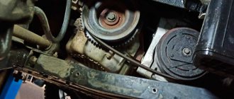
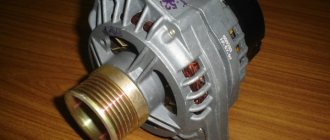
Generator VAZ 2110 converts the mechanical energy of crankshaft rotation into electrical energy, which is used to charge the battery and operate the “tens” electrical networks. Torque is transmitted through the generator drive belt, which connects the engine crankshaft pulley and the generator pulley itself.
The alternator belt is the most important element in the engine-generator connection. If the belt breaks, replacing it is not particularly difficult. Just loosen a couple of nuts. The main difficulty is to ensure correct belt tension.
VAZ 2110 generator belt, tension check
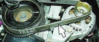
Checking the tension of the VAZ 2110 generator belt must be carried out periodically. If the tension is weak, the alternator belt may simply slip, especially during wet weather. As a result, poor belt tension can lead to insufficient battery charging. But you should not overtighten the alternator belt; this will lead to rapid wear of the belt itself or its unexpected break. In addition, when the belt is overtightened, the generator bearings are subject to additional stress and wear out quickly. Below is a schematic drawing that will help you understand how to properly tension the VAZ 2110 alternator belt.
- 1 – upper bracket of the generator
- 2 – nut
- 3 – generator adjusting bolt
- 4 – generator
- 5 – bolt for hinge mounting of the generator to the bottom bracket
- 6 – generator belt
- 7 – drive pulley on the crankshaft
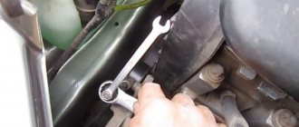
To ensure normal deflection of the VAZ-2110 generator belt, which is indicated as “A” in the schematic diagram, it is necessary to loosen the generator nut “2” and the bolt nut “5”. Then, by rotating the adjusting bolt “3”, you can move the generator closer/further from the engine, thereby loosening/tensioning the generator belt. The normal deflection of belt “A” should be from 6 to 10 mm, subject to pressure on the belt with a force of 98 N or 10 kgf.
Dismantling and repair
After you have succeeded in removing the device, you need to perform an inspection and find defective parts. It is better to carry out diagnostics at a service station in order to be sure which part needs to be removed and a new one installed. The work must be carried out in a garage with an inspection hole. Disassembly is performed as follows:
- The negative terminal must be disconnected from the battery;
- The next step is to remove the power plant mudguard. After this, access to the generator excitation wires will appear - they must be removed;
- Using a 10mm wrench, you need to unscrew the nut that secures the wires to the positive drive. Now both wires can be removed;
- Next you need to remove the belt. Having opened access to the device, unscrew the adjusting bolt and then pull the unit out of the top bracket;
- Now you can remove the tension bar. While holding the device, unscrew the lower fastening nut and remove the bolt;
- Disassembly is complete - the unit can be removed.
After performing troubleshooting, you can understand whether the VAZ 2110 generator needs to be replaced or not. In some cases, it will be enough to replace a few worn parts. When disassembling, you should have a diagram at hand. If you have no experience working with electrical appliances, it is better to contact a service center.
Design of the VAZ 2110 generator
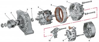
A working generator should deliver from 13 to 14.5 volts to the battery terminals. If this indicator is less when the engine is running and warm, then the generator is faulty. There should be no sudden jumps when consumers are turned on. If the charge is more than 15 volts, this is just as bad; overcharging will quickly damage the battery. When overcharging, water boils away from the electrolyte and the plates crumble. The main reason for the increased charge is the failure of the voltage regulator. Below is a schematic and very detailed image of the VAZ 2110 generator
- 1 – generator pulley
- 2 – washer
- 3 – front cover
- 4 – spacer ring
- 5 – generator rotor
- 6 – generator stator
- 7 – back cover
- 8 – casing
- 9 – rectifier unit with capacitor
- 10 – brush holder with voltage regulator
Very often the voltage regulator fails; replacing it is not difficult, since it is not necessary to completely disassemble the VAZ 2110 generator. But due to the fact that the voltage regulator and current-collecting brushes are a single and non-separable part, the replacement is carried out together with the generator brushes.
Often, owners of “ten” are faced with replacing additional diodes that are located on the rectifier block, in the figure above, numbered “9”. To replace generator diodes, you must have epoxy resin and a soldering iron. Using a soldering iron, you need to carefully unsolder the damaged one and solder a new diode. And the resin is necessary for reliable gluing of the diode body. In this case, the old resin must be cleaned off.
avtoel43 › Blog › Auto electrics. Search and prevention of battery charge. Wires.
Well guys, hello to you again! I am starting a series of articles on searching for voltage sags and lack of battery charge. In this article I will tell you about the problem of wires and bad connections, as well as about childhood problems of VAZ.
You have often encountered the fact that the voltage in the car’s on-board network sags when consumers are turned on, and many of you thought that this was how it should be, even if the voltage dropped to 13V and a little lower. In fact, it shouldn’t be like this! The operating voltage in the on-board network, even with consumers, should not be lower than 13.6. But there are those who don’t like drawdowns. Usually everyone starts immediately removing the generator, changing the RR (regulator relay), DM (diode bridge), but this is a mistake! First you need to ring the wires and all connections. In my practice: 70% of cases are a problem of bad connections, 30% are a generator (and this is also a problem of bad connections).
Generator bearing VAZ 2110
Another problem with the VAZ 2110 generator is the rotor bearing. More precisely, two rotor bearings, one at each end of the generator rotor shaft. The front bearing is rolled into the front cover of the generator; the entire assembly is not dismountable, so the bearing must be replaced with the entire cover assembled. The situation with the rear bearing is as follows; it is simply pressed onto the shaft. To remove it you will need a special bearing puller. It is advisable to use a vice to install a new bearing. Because the rotor shaft on which you will press the new bearing must be stationary.
Resource
The standard Katek generator on the VAZ 2110 is designed to operate over a range of 140 thousand kilometers, which in terms of operating time is about 10 years. But this, however, is subject to the rules of handling it.
Many people doubt whether a powerful 120-amp generator will have a negative impact on the battery. Practice shows that it is not, but if you have a powerful sound system in your car, it will be just right.
Electrical circuit of the VAZ 2110 generator
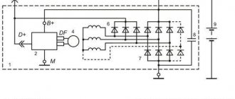
The electrical circuit of the VAZ 2110 generator is shown in the detailed figure below.
Basic elements of an electrical circuit.
- 1 – battery
- 2 – generator
- 3 – mounting block
- 4 – ignition switch
- 5 – battery charge indicator lamp, located in the instrument cluster
The “ten” generator is an alternating current unit, three-phase, with a built-in rectifier unit and an electronic voltage regulator. Over the years, generators of both domestic and foreign production were installed on the VAZ-2110, 2111 and 2112 family. Therefore, they may differ structurally.
What to choose?
In terms of popularity and reliability, the first places are occupied by manufacturers Bosch (Bosch), Denso (Denso) and Delphi (Delphi). But you should know that Katek (KZATE) (made by us) are also quite reliable and do a good job of their duties on the VAZ 2110, creating the required voltage. Maybe somewhere they lose against Bosch, but compared to the Chinese they are at their best.
VAZ generators of the tenth family:
Staff - KATEK, KZATEtm (Samara)
Kraft
PRAMO/ELTRA (Rzhev)
So it’s difficult to say for sure which generator is right for you; the best one is the one that provides the necessary power to operate electrical appliances and charge the battery. If we take the advantages that Katek clearly has, then this is sufficient reliability, and also - what is important - the availability of inexpensive spare parts for sale: you can always buy at least a fuse, a pulley, an armature, a voltage regulator, an excitation wire, etc.
Add a comment Cancel reply
You must be logged in to post a comment.
1 — casing 2 — “B+” terminal for connecting consumers 3 — interference suppression capacitor 2.2 μF 4 — common terminal of additional diodes (connected to the “D+” terminal of the voltage regulator) 5 — holder of positive diodes of the rectifier unit 6 —- holder of negative diodes of the rectifier unit 7—- positive diode 8—- negative diode 9 —— voltage regulator 10 —— back cover 11 —— coupling screw 12 —— front cover 13 —— stator winding 14 —— spacer ring 15 —- front rotor shaft bearing 16 — pulley
17 - nut 18 - rotor shaft 19 - cone washer 20 - washer 21 - beak-shaped rotor pole pieces 22 - stator core 23 - bushing 24 - rotor winding 25 - rear rotor bearing 26 - bearing bushing 27 — slip rings 28 — brush holder 29 — stator winding terminals 30 — additional diode 31 — terminal “D” (common terminal of additional diodes)
The generator is a synchronous AC electrical machine with electromagnetic excitation and a built-in rectifier using silicon diodes. The generator rotor is driven into rotation from the engine crankshaft pulley (damper) by a poly-V belt.
Technical characteristics of generator 94.3701
Maximum output current (at 13 V and 6000 rpm), A
Voltage, V
Engine-generator gear ratio
Direction of rotation (drive side)
The stator and generator covers are secured with four screws. The rotor shaft rotates in bearings installed in the covers. The lubricant placed in the bearings at the factory is designed to last the entire service life of the generator. The rear bearing is pressed onto the rotor shaft and is pressed by the rear cover through a plastic sleeve. The front bearing is pressed and rolled into the front cover and can only be replaced together with it. Its inner race, together with the spacer ring and washer, is clamped by a nut between the pulley and the step on the rotor shaft. The back of the generator is closed with a plastic casing with latches.
Rotor and stator
The stator is the stationary part of the generator, consisting of a three-phase element. The winding of the device is designed to create alternating current. In turn, the rotor is designed to create a magnetic field. This is a rotating element that receives power from slip rings. The drive pulley, fan impeller, bearings and field winding wires are also located here.
When considering the generator on the VAZ 2110 injector, you cannot ignore the rectifier unit, the function of which is to transform alternating current into direct current. The block contains 6 diodes
The device provides battery charging
Another important part of the device is the belt drive. Its purpose is to increase speed depending on the degree of rotation of the crankshaft
In modern cars, a poly-V drive is installed. It is recommended to install it on the tens generator. The advantage of the belt is its high wear resistance
The block contains 6 diodes. The device provides battery charging
Another important part of the device is the belt drive. Its purpose is to increase speed depending on the degree of rotation of the crankshaft
In modern cars, a poly-V drive is installed. It is recommended to install it on the tens generator. The advantage of the belt is its high wear resistance.
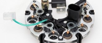
Also in the VAZ-2110 car generator there are two important elements: a brush holder assembly and a brush assembly. The brush holder assembly is found in modern Katek devices.
Generator device
The design of a car generator implies the presence of its own rectifier and control circuit. The generating part of the generator, using a stationary winding (stator), generates three-phase alternating current, which is then rectified by a series of six large diodes and the direct current charges the battery. Alternating current is induced by the rotating magnetic field of the winding (around the field winding or rotor). Next, the current is supplied to the electronic circuit through the brushes and slip rings.
Generator structure: 1.Nut. 2. Washer. 3.Pulley 4.Front cover. 5. Distance ring. 6.Rotor. 7.Stator. 8.Back cover. 9.Casing. 10. Gasket. 11.Protective sleeve. 12. Rectifier unit with capacitor. 13.Latch holder with voltage regulator.
The generator is located at the front of the car engine and is started using the crankshaft. The connection diagram and operating principle of a car generator are the same for any car. There are, of course, some differences, but they are usually associated with the quality of the manufactured product, the power and the layout of the components in the motor. All modern cars are equipped with alternating current generator sets, which include not only the generator itself, but also a voltage regulator. The regulator equally distributes the current in the excitation winding, and it is due to this that the power of the generator set itself fluctuates at a time when the voltage at the power output terminals remains unchanged.
The principle of operation of a car generator
Connection diagram for the VAZ 2110-2115 generator
The alternator connection diagram includes the following components:
- Battery.
- Generator.
- Fuse block.
- Ignition.
- Dashboard.
- Rectifier block and additional diodes.
The principle of operation is quite simple: when the ignition is turned on plus through the lock, the ignition goes through the fuse box, light bulb, diode bridge and goes through a resistor to minus. When the light on the dashboard lights up, then the plus goes to the generator (to the excitation winding), then during the process of starting the engine, the pulley begins to rotate, the armature also rotates, due to electromagnetic induction, electromotive force is generated and alternating current appears.
Next, the diode passes plus into the rectifier block through a sine wave into the left arm, and minus into the right arm. Additional diodes on the light bulb cut off the negatives and only positives are obtained, then it goes to the dashboard assembly, and the diode that is there allows only the negative to pass through, as a result the light goes out and the positive then goes through the resistor and goes to the negative.
The principle of operation of a car DC generator can be explained as follows: a small direct current begins to flow through the excitation winding, which is regulated by the control unit and is maintained by it at a level of slightly more than 14 V. Most generators in a car are capable of generating at least 45 amperes. The generator operates at 3000 rpm and above - if you look at the ratio of the size of the fan belts for the pulleys, it will be two or three to one in relation to the engine frequency.
To avoid this, the plates and other parts of the generator rectifier are partially or completely covered with an insulating layer. The heat sinks are combined into a monolithic design of the rectifier unit mainly by mounting plates made of insulating material, reinforced with connecting bars.
Ways to troubleshoot battery problems
First of all, you need to check the battery charging while the engine is running. During normal charging, the voltage will be in the range of 13.6 - 14.2 Volts. If the charge is weak, the value will be below 12 Volts (the author of the video is VAZ 2101-2107 repair and maintenance).
To troubleshoot problems, you need to prepare instructions with a diagram of the electrical equipment of the VAZ 2110 car and the necessary tools:
- pliers;
- flat and Phillips screwdrivers;
- multimeter;
- 12 V indicator light;
- knife;
- sandpaper.
There are the following troubleshooting methods, which can be determined by how the battery light lights up and goes out:
- If the charge indicator on the dashboard does not light up, this indicates that the battery is low. The reason why the battery is not charging may be due to oxidized contacts. The contacts on the battery should be cleaned. If this does not help, you need to measure the voltage at terminal “30” of the generator. To do this, one probe must be connected to ground, and the second to terminal “30”. If the flowing current greatly exceeds the charge on the battery, it is necessary to clean the terminal on the generator. It is possible that the wire connecting the generator to the device needs to be replaced.
- If the voltmeter on the dashboard and the warning light show that there is a charge, but the battery is discharged. In this case, the charge at the terminals is within normal limits, and when the equipment is turned on, the charge arrow occupies the extreme left position. This indicates insufficient tension on the generator drive belt or damage to it.
- The battery may not charge due to a breakdown in one of the diodes, as well as a break in the starter winding. In this case, with the ignition off, use a multimeter to check the diodes and, if necessary, replace them.
- The battery is not charging, but the indicator does not light up and the charge sensor does not work. The reason is a blown fuse F10.
- If the ignition is on, all devices are working, the charging indicator does not light up, and there is no charge, then you need to check the generator. To do this, remove the wire from terminal “61” on the generator and connect it to the car body, which will act as a “minus”. A lit battery indicator indicates a problem in the excitation winding of the generator device. The reason may be poor contact at the connection point. In this case, you need to clean the contacts. If this does not fix the problem, it is possible that the cause is a burnt-out lamp.
- When you turn the key in the ignition, the battery charging light comes on, but when the engine starts, it does not go out. In this case, there is no charging or it may periodically disappear, this indicates that the battery is discharging. The reason is insufficient contact in the place where the instrument panel is connected. It is possible that they have oxidized and need to be cleaned.
- The relay regulator should also be checked. To do this, you need to apply voltage to the contacts from the battery. If it is 12 volts at the brushes, then the relay is working properly. Otherwise it should be replaced.
- If the electrolyte level is insufficient, add the required amount of distilled water.
- If the battery case is damaged or the service life has expired, it should be replaced.
Sorry, there are no surveys available at this time.
Generator connection diagram for VAZ 2107
The VAZ 2107 charging scheme depends on what type of generator is used. To recharge the battery on cars such as VAZ-2107, VAZ-2104, VAZ-2105, which have a carburetor engine, you will need a G-222 type generator or its equivalent with a maximum output current of 55A. In turn, VAZ-2107 cars with an injection engine use a generator 5142.3771 or its prototype, which is called a high-energy generator, with a maximum output current of 80-90A. It is also possible to install more powerful generators with an output current of up to 100A. Absolutely all types of alternating current generators have built-in rectifier units and voltage regulators; they are usually made in the same housing with brushes or are removable and mounted on the housing itself.
The VAZ 2107 charging circuit has minor differences depending on the year of manufacture of the car. The most important difference is the presence or absence of a charge indicator lamp, which is located on the instrument panel, as well as the method of connecting it and the presence or absence of a voltmeter. Such circuits are mainly used on carburetor cars, while on cars with injection engines the circuit does not change, it is identical to those cars that were manufactured previously.
Generator set designations:
- “Plus” of the power rectifier: “+”, V, 30, V+, WAT.
- “Ground”: “-”, D-, 31, B-, M, E, GRD.
- Excitation winding output: Ш, 67, DF, F, EXC, E, FLD.
- Output for connection to the serviceability lamp: D, D+, 61, L, WL, IND.
- Phase output:
,W,R,STA.
- Output of the stator winding zero point: 0, MP.
- Output of the voltage regulator for connecting it to the on-board network, usually to the “+” of the battery: B, 15, S.
- Voltage regulator output for powering it from the ignition switch: IG.
- Voltage regulator output for connecting it to the on-board computer: FR, F.
Generator circuit VAZ-2107 type 37.3701
- Accumulator battery.
- Generator.
- Voltage regulator.
- Mounting block.
- Ignition switch.
- Voltmeter.
- Battery charge indicator lamp.
When the ignition is turned on, the plus from the lock goes to fuse No. 10, and then goes to the battery charge indicator lamp relay, then goes to the contact and to the coil output. The second terminal of the coil interacts with the central terminal of the starter, where all three windings are connected. If the relay contacts close, then the control lamp lights up. When the engine starts, the generator generates current and an alternating voltage of 7V appears on the windings. Current passes through the relay coil and the armature begins to attract, and the contacts open. Generator No. 15 passes current through fuse No. 9. Similarly, the excitation winding receives power through the brush voltage generator.
Charging diagram for VAZ with injection engines
This scheme is identical to the schemes on other VAZ models. It differs from the previous ones in the method of exciting and monitoring the serviceability of the generator. It can be carried out using a special control lamp and a voltmeter on the instrument panel. Also, through the charge lamp, the generator is initially excited at the moment it starts working. During operation, the generator operates “anonymously,” that is, excitation comes directly from pin 30. When the ignition is turned on, power through fuse No. 10 goes to the charging lamp in the instrument panel. Then it goes through the mounting block to pin 61. Three additional diodes provide power to the voltage regulator, which in turn transmits it to the excitation winding of the generator. In this case, the indicator lamp will light up. It is at that moment when the generator operates on the plates of the rectifier bridge that the voltage will be much higher than that of the battery. In this case, the control lamp will not light up, because the voltage on its side on the additional diodes will be lower than on the side of the stator winding and the diodes will close. If the control lamp lights up while the generator is running, this may mean that additional diodes are broken.
How does he work
First, let's figure out how this device functions. His work scheme is as follows:
- The key is inserted into the ignition switch;
- The current goes to the excitation wires;
- The magnetic field created by the armature passes through the stator windings, and voltage appears at its terminals;
- When the armature rotation frequency becomes high enough, the self-excitation mode begins;
- The rectifier unit provided by the car design converts alternating current into direct current;
- The voltage regulator starts working when the crankshaft rotation speed changes, and the time for which the excitation wire is activated is adjusted.
Checking generator operation
You can check the functionality of the generator in several ways using certain methods, for example: you can check the output current of the generator, the voltage drop on the wire that connects the current output of the generator to the battery, or check the regulated voltage.
To check, you will need a multimeter, a car battery and a lamp with soldered wires, wires for connecting between the generator and the battery, and you can also take a drill with a suitable head, since you may have to twist the rotor by the nut on the pulley.