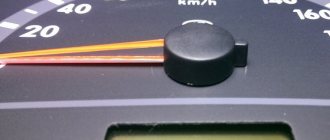
Cars are equipped with analogue, electronic speedometers with a mechanical drive and fully electronic speed meters. Each type of device is characterized by its own malfunctions and symptoms of their manifestation. Let's look at how a car speedometer works, common breakdowns, and reasons for the failure of the speed sensor and indicator inside the dashboard.
Speed reading principle
The operating principle of the speedometer of a modern car is based on two types of sensors:
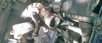
- Speed sensor with mechanical drive. By means of a gear transmission, the rotation speed of the gearbox output shaft is transmitted to the sensor shaft. When the vehicle is moving, the speed sensor generates a sequence of rectangular pulses, which is sent to the input of the electronic speedometer and electronic control units (ECU, ABS control unit, automatic transmission, etc.). Speed meters are based on magnetic induction or the Hall effect and are installed on the gearbox;
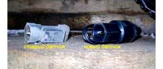
- Wheel speed sensor. To measure vehicle speed, a signal from one of the ABS sensors is used. According to their internal structure and operating principle, meters are divided into active and passive. The first type includes Hall effect sensors, which require an external power source to generate pulses. The second type is represented by inductive sensors that produce sinusoidal alternating voltage. The rotation speed is read using a sensing element that reacts to the rotation of a gear (drive disk) mounted on a wheel bearing or drive shaft. Speedometer failure with this type of design is often accompanied by an ABS system malfunction indicator.
Influence of weather conditions
A decrease in air temperature can also cause a decrease in tire pressure. Pressure may drop 3 to 4 psi, especially in very cold temperatures.
- A decrease in pressure can also be recorded in tires that have been standing motionless for a long time from night to morning.
- Low tire pressure causes the tread to bleed and, as a result, reduce the tire diameter.
- For this reason, the vehicle speed may be lower than the value displayed on the speedometer.
However, when the tires warm up, the pressure returns to normal and thus the tire diameter returns to its previous condition.
Operating principle of the speed sensor
A magnet is installed inside the magnetoresistive element (MRE) sensor, which is connected through a shaft to the speedometer drive gear. An integrated circuit built into the magnetoresistive element is installed above the magnet. The resistance of the element changes depending on the direction of the magnetic field. Rotation of the magnet provokes a change in the magnetic field near the MRE, which is detected by an integrated circuit and transformed into a square wave signal. A variable frequency sensor transmits a signal voltage to ground (the frequency depends on the speed of rotation of the gear wheel).
The Hall effect speed sensor is based on the property of certain rectangular-shaped conductors/semiconductors to generate a voltage if their opposite planes are penetrated at right angles by magnetic field lines. As is the case with MRE-based sensors, inside the housing the response of the sensing element is transformed by electronic circuitry into a square wave signal.
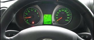
Why doesn't the speedometer work?
The main reasons for speedometer failure:
- speed sensor failure;
- contact failure in the sensor power circuit. Connections should be checked for bent or oxidized pins. There should be no parasitic resistance on the wire sections, which appears when the wire insulation is damaged and the internal oxidation of the conductor;
- malfunction of the worm drive that transmits rotation from the secondary shaft of the gearbox to the gear wheel of the speed sensor;
- breakdown of the speed indicator inside the dashboard. Most often, a speedometer malfunction is associated with poor contact due to the appearance of solder cracks on the board;
- failure of the electronic engine control unit (ECU). On some cars (for example, Daewoo Gentra), the signal from the speed sensor first goes to the ECU and only then is sent to the dashboard. Due to the leakage of the ECU housing, corrosion damages the electrical circuit of the speed signal, which leads to the speedometer not working.
Tire pressure
Tire pressure should be adjusted according to the number of people in the vehicle and the load it is carrying. This is quite important from the point of view of driving safety and tire durability.
Therefore, manufacturers specify what pressure should be applied to which tire on the fuel cap or inside the door for different conditions. You can see this clearly in the picture above.
- On the other hand, tire pressure affects the car's speedometer readings.
- The speedometer measures the tire at its ideal pressure. Changing tire pressure will cause the speedometer to display different, often incorrect, data.
- Because a tire with higher pressure will increase in diameter, the speedometer will show a lower value than the driving speed.
- The speedometer will show a higher value than the speed traveled because the diameter of the tire with full travel at low pressure will decrease.
Additionally, if the vehicle is loaded with a certain amount of cargo or is driven in close quarters, the sidewalls of the tire will flex slightly, as if the pressure is low. This causes the tire diameter to decrease and the speedometer to display a higher value than the speed traveled.
How to check the speed sensor?
If the speedometer on your car stops working, start by checking the speed sensor. Disconnect the sensor's power connector, then use a multimeter to check the following values:
- The presence of "mass". Test conditions: multimeter in “continuity” mode, measurements are taken from the negative terminal of the battery and the “ground” contact in the connector. The resistance should be close to 0.
- Availability of supply voltage. Test conditions: ignition on, multimeter in DC measurement mode, measurements from the negative terminal of the battery and contact “31” of the sensor power connector. The voltage should be equal to or slightly less than the voltage at the battery terminals.
- Availability of reference voltage. Test conditions: ignition on, multimeter in DC measurement mode, measurements from the negative terminal of the battery and the signal pin in the speed sensor connector. The voltage should be in the range of 4.5-5 V or slightly less than the voltage at the battery terminals (depending on the device characteristics of a particular car model).
In the absence of an oscilloscope, with which you can view the presence and shape of output signal pulses, you can use an LED control connected to the signal pin of the speed sensor. When the speedometer drive gear rotates, the LED should blink.
Electrical diagram
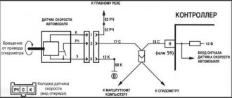
The sensor itself is powered by a voltage of 12 Volts (pink-black cord), and another pin is connected to ground. The gray wire is the sensor output. It is connected to the voltage source through a resistor (see figure).
Typical connection diagram for DS on a VAZ-2112
The diagram shows that the output is connected to the ECU terminal. Terminal number:
- 9 – block January 5.1, also BOSCH M1.5.4N (engine 21120, 1.5 l);
- 59 – BOSCH M7.9.7 module (ICE 21124, 1.6 l).
Another gray cord goes to the “red” block on the dashboard, where it connects to terminal 9.
As you can see, everything is elementary.
How does an analog speedometer work?
The drive of the analog speedometer in the dashboard is realized through a flexible cable from the secondary shaft of the manual transmission. The cable is engaged with the shaft through a worm gearbox. There are dial, tape and drum speedometers. The last two design options are already difficult to come across in our time, so let’s consider the design of a dial speed meter.
All analog speedometers of this type of design are designed using the effect of magnetic induction. A unit was built on the basis of a rotating magnet and a card covering the magnet. When the magnet rotates near the aluminum card, eddy currents are induced. The deflection of the needle is proportional to the strength of the eddy currents.
A variation of the design is a speedometer based on a magnet and a metal plate connected to the speedometer needle by a common axis. A flexible cable from the manual transmission transmits rotation to a magnet, which, through the phenomenon of magnetic induction, when moving, carries along a ferromagnetic plate. When the vehicle speed decreases, the arrow returns to its original position due to the return spring.
The odometer drive, which measures the distance traveled, is implemented using the same flexible cable. Inside the speedometer, using a worm gear, the rotation of the cable is transformed into the movement of sections of the distance traveled.
Typical failures of an analog speedometer
- Breakage of the flexible shaft. The reason is the natural aging of the metal or mechanical impact on the casing, as a result of which the shell and cable rub against the car body and parts of attachments.
- Breakage of the worm gear that transmits rotation of the gearbox secondary shaft to the cable. Often the flexible shaft drive is made of plastic, which is why, at long runs, the gear teeth are licked off and the cable seat in the housing is damaged. Less common is a breakdown of the drive drive inside the gearbox, due to which the rotation of the secondary shaft is not transmitted to the cable.
- There is a malfunction in the speed display mechanism inside the dashboard.
- Extraneous sound when accelerating. The reason is a frayed cable or improper installation of the flexible shaft, which causes the cable to exert increased resistance on the casing when rotating.
Video: The speedometer in the car does not work. How to find the reason? AUTO electrician advice.
If the described factors have been eliminated, and the speedometer continues to make strange sounds, try dripping silicone grease/engine oil into the casing on the dashboard side.
To check the speedometer operation, remove the flexible cable housing from the gearbox. Unwind the flexible shaft, fixing the cable into the drill chuck. If the speed is displayed on the dashboard, then the problem is in the master drive inside the transmission. If the speedometer needle does not move, disconnect the flexible shaft from the instrument panel. If during forced unwinding the reverse end of the cable does not rotate, the cause of the speedometer failure is a break in the flexible shaft. If the cable rotates, the speed is not displayed due to a broken indicator.
Instrument panel test on video (speedometer self-diagnosis)
There are some things we don't specifically consider.
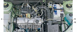
Power to the circuit shown in the previous chapter comes from main relay 6. It is also called the “ignition relay”. There is also fuse 1 in the circuit.
Additional relay and fuse box
When the ignition circuit is broken, both the speedometer and the ECU module do not work on the VAZ-2112, and the engine does not start at all. So advice about checking the relay would seem stupid.
Advice for those who have an oscilloscope
If you still decide to dismantle the sensor, connect a 1 kOhm resistor to its output (to the middle terminal). The resistor tap is connected to the “plus” of the power supply. By turning the shaft by hand, pulses can be observed at terminal 2. There are six pulses per revolution.