Adjusting the idle speed of carburetors is most often in demand for domestic cars. In this article we will look at how adjustments are made correctly and what tools are needed for this. At the end of the article we tell you how to find a good specialist in carburetor engines to carry out adjustments.
Find out the cost of idle adjustment online in 3 minutes
Don't waste your time - use the Uremont search and get offers from nearby services with specific prices!
Get prices
Idle system design
The designs of modern carburetors contain not only the main metering system. It alone would not allow obtaining the necessary mixture composition to maintain normal engine operation in no-load mode, in other words, when the engine should be idling. The system of the same name is responsible for normal operation in idle mode. Let's consider one of the options for its design.
Design of the idle system: 1 - transition hole;
2 - air channel; 3 - idle mixture screw; 4 — hole for low idle speed; 5 - fuel channel; 6 - fuel nozzle combined with an emulsion tube. The idle system includes two fuel supply holes. They have special names: transition hole 1 and low idle speed hole 4 (location options on a real carburetor are shown in the figure below). The transition hole is located under the throttle valve, in close proximity to its trailing edge. The low idle speed hole is located behind the throttle valve, a short distance away at the point where the vacuum is greatest when the throttle valve is closed. This situation is due to the desire to ensure the easiest flow of fuel from the low idle speed hole.
Options for the location of fuel supply holes: 1 - transition hole; 2 - hole for low idle speed
In the fuel supply channel 5 of the idle system there is a nozzle 6, which limits the flow of fuel when idling. In the same channel there is an emulsion tube (often combined with a jet), in which the fuel is mixed with air entering through air channel 2.
Fine-tuning elements include screw 3, which regulates the cross-section of the air channel. In this design, the screw influences the composition of the mixture. Below we will consider a design in which a similar screw regulates the amount of mixture.
Setting up the float mechanism
The level of the fuel mixture in the float chamber is directly related to its quality. At an increased level, the mixture will turn out to be lean, which will negatively affect gasoline consumption and increase toxicity. Without adjusting the floats, the question of how to adjust the carburetor cannot be solved. The process of adjusting the floats includes the following operations:
- Adjusting the floats in relation to the lid and walls of the fuel chamber. If deformation of the float fixing bracket is noticed, it should be aligned manually;
- We adjust the bracket with the needle valve closed;
- We adjust with the float retracted and the valve open; the distance between the float and the valve should in this case be set to about 15 millimeters.
Emulsifying fuel in the idle system
In the idle system, fuel is mixed with a small amount of air, which enters through a special air channel. The fuel emulsification process occurs as follows. When the throttle valve is closed and the fuel mixture is supplied only through the low idle speed hole, the fuel is mixed with air entering not only through the air channel, but also with air from under the throttle valve passing through the transition hole. As the throttle rises, the zone of maximum vacuum moves towards the nozzle of the main dosing system. In this regard, the amount of air entering the idle system through the transition hole is reduced. At some point in the throttle lift, air completely stops flowing from the transition hole, and under the influence of rarefaction, fuel begins to gush through it. At this moment, all air begins to flow only through a special air channel, the throughput of which is regulated by a conical screw.
Conclusion
As you yourself have seen, a carburetor is a complicated thing, but you don’t need any special intelligence to adjust the idle speed. Do not try to repeat the procedure if your “Seven” is on gas, the process will be pointless because the carburetor does not work with this type of fuel. You can try to set up the injector, but there is a high probability of only harming the device, since the actions described there are ineffective, so it is better to turn to professionals. All the procedures described and more are clearly demonstrated in the video, where the cheerful specialist easily and simply finds a common language with the carburetor. I wish the same for you, all the best!
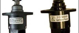
Idle mixture adjustment screw
The final (fine) adjustment of the idle air system is made using a special screw with a conical tip, which regulates the throughput of the air channel of the idle air system. Some carburetor models are equipped with a screw that regulates the amount of fuel, already pre-mixed with air, supplied by the idle system.
Idle mixture adjustment screws. Two screws on the left regulate the amount of mixture, two on the right control the composition of the mixture.
Since in one case the screw regulates the composition of the mixture, and in the other - the amount of the fuel mixture, opposite adjustment methods are used. If the screw regulates the throughput of the air channel, then to enrich the mixture it is necessary to reduce the amount of air by tightening the screw. In order to make the mixture leaner, the screw must be unscrewed. If the screw regulates the amount of fuel supplied, then, on the contrary, to enrich it, it is unscrewed, and to become lean, accordingly, it is tightened.
It is very simple to understand by what principle adjustment is carried out on a particular carburetor. The air adjustment screw is located closer to the carburetor inlet, which is connected to the filter, while the fuel adjustment screw is located closer to the engine mounting flange.
Location of the idle mixture adjustment screws: a — mixture adjustment screw, b — mixture amount adjustment screw
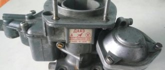
Do-it-yourself dismantling of the unit
To remove the DAAZ 2107 carburetor, auto mechanics recommend proceeding in the following sequence:
- The hood of the car is opened, the clamp on the warm air intake hose is loosened using a flat screwdriver, after which the hose is disconnected from the thermostat tube.
The air intake hose is disconnected from the thermostat
The mounting plate of the DAAZ 2107 carburetor is removed manually
The air filter from the VAZ 2107 is removed after removing the mounting plate
The choke cable of the DAAZ 2107 carburetor is disconnected using a screwdriver
The hose for removing crankcase gases from the DAAZ 2107 carburetor is removed manually
The wires of the economizer control system are disconnected from the DAAZ 2107 carburetor without much effort
The hose of the vacuum ignition timing regulator is removed from the DAAZ 2107 carburetor by unscrewing the screws
The solenoid valve control hose is manually removed from the DAAZ 2107 carburetor
The return spring of the solenoid valve of the DAAZ 2107 carburetor is manually removed from the socket
Fuel hoses from the DAAZ 2107 carburetor are removed manually after loosening the clamps
The DAAZ 2107 carburetor mounting nuts are unscrewed with a 14-mm open-end wrench
After unscrewing the fasteners, the DAAZ 2107 carburetor is removed manually
Idle jet
If a jet of too large a capacity is installed, the engine begins to operate unstably, slowly picks up speed, and the exhaust sound becomes dull and weak.
If the jet has insufficient flow, the engine revs well, but when the throttle is closed sharply, the revs do not drop as quickly. The reduction in speed to idle occurs with a delay of up to several seconds. Too little throughput leads to unstable operation and frequent engine stops, both in low idle mode and when trying to raise the throttle. Operating the engine with an insufficient idle jet installed can result in the piston sticking to the cylinder wall when the throttle valve is closed. The risk is especially great if the engine has previously been running at full throttle for a long period of time. Under such conditions, after closing the throttle, the engine maintains high speed by inertia. If the idle system is running lean at this point, the heat load increases dramatically due to excessive lean combustion, increasing the risk of overheating and subsequent stalling.
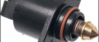
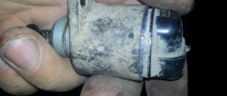
EPH sensor is faulty
The idle speed economizer or idle speed sensor is located under the hood of the VAZ 2107 and is screwed to the side of the carburetor. It is a small cylindrical electromagnet screwed into the unit. On the back side of the valve there is a contact, the wire from which goes to the power circuit of the ignition switch.
EPHH control unit: 1 — block outputs; 2 - body; 3 - printed circuit board with microelectronic elements.
If the carburetor cannot be adjusted in any way or the VAZ 2107 does not idle, and the idle speed disappears very quickly or the engine is unstable, then it makes sense to start the engine and try to unscrew the valve a little. If the operation of the carburetor engine is restored, tighten the valve with a little force and try changing the amount of mixture. In 90% of cases, the carburetor starts working correctly again.
Another case is complete valve failure. To do this, you need to check it. You need to connect it directly to the battery. If clicks are heard, then the valve is working. Try screwing it into the carburetor and starting the engine. If successful, you need to look for a break in the electrical wiring and then you won’t need to adjust xx.
Operation of the idle system in transient mode
When the driver begins to open the throttle slightly, the vacuum in the area of the low idle speed hole decreases.
This leads to a decrease in the supply of fuel through it, so another system must be activated to ensure a smooth transition in operation from the idle system to the main metering system. When the throttle valve rises to approximately 1/4 of the entire stroke, the vacuum in the area of the low idle hole drops so much that the flow of fuel from it stops. The area of maximum vacuum moves closer to the nozzle of the main dosing system, but does not yet reach it. The transition hole is located exactly in this place. Fuel begins to flow out of it in an amount sufficient to ensure a smooth transition in engine operation from idle to partial load mode, when the main metering system is already operating.
Note that the idle jet is important not only for low idle operation, but also for transient operation, since it also regulates the amount of fuel flowing from the transition hole. Along with the jet, operation in transient modes is influenced by the angle of the throttle valve, a special protrusion on the rear of the throttle valve, the shape of the nozzle around the nozzle of the main metering system, and a special groove on the rear edge of the throttle valve.
Throttle valve elements affecting transient behavior. The color indicates the protrusion on the rear of the throttle body (a) and the special groove on the trailing edge (b).
To be continued…