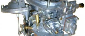
Basic adjustment work
Carburetor and its components
Experienced mechanics know how to adjust the carburetor on a VAZ. When turning the damper lever counterclockwise, the last element closes. If this does not happen, it is necessary to find out and eliminate the cause of the spring jamming.
To do this, you will have to press the VAZ 2105 carburetor rod all the way. The shock absorber will open 3 mm. The distance is adjusted with a screw. If the valve is open, a similar element of the throttle valve of the 1st chamber should be slightly open by 1.1 mm.
The idle speed of the VAZ 21053 carburetor is adjusted with screws. The first is related to the amount of the mixture, the second - to its composition. The last element is closed with a cap. The carburetor VAZ 2105 1107010 20 can be adjusted to an engine heated to a temperature of 90-95 ° C. Also checked:
- correct setting of the gas distribution unit,
- degree of opening of the air damper,
- ignition system advance angle.
It is necessary to start adjusting the VAZ 21053 carburetor by setting the engine crankshaft speed, taking into account the speedometer readings at 750-800 rpm. Using the second screw, which is responsible for the composition of the mixture, it is necessary to obtain an appropriate concentration of carbon monoxide in the exhaust gases, equal to 0.05 Jy, 2%.
Preliminary stage
Before you properly adjust the carburetor on a VAZ 2106 with your own hands , it is important to carry out a number of work steps:
- Adjust the thermal clearances of the gas distribution mechanism.
- Set the optimal ignition timing.
- Open the air damper completely.
All work on setting up the carburetor unit is carried out on a warm engine. Do not forget that during the process you may need new parts and rubber products, so it is better to purchase a repair kit in advance.
Setting up the Ozone carburetor
Often the “seven” is equipped with an “Ozone” carburetor. This unit is configured according to a certain scheme. It should be noted that replacing a needle valve involves adjusting the level of the substance in the corresponding chamber.
Having disassembled the VAZ 2105 carburetor cover, you need to make sure that the float is in a free position and can easily rotate on its axis. There are no holes or dents and the bedroom wall is not touching. The tightness of the needle valve seat is checked, including the free movement of the ball in the corresponding hole.
We are rebuilding the minimum
When adjusting the Ozone carburetor, it is necessary to keep the cover in a vertical position with the fitting facing up. Please note that the gap between the float and the gasket should be 6.5 mm. The important point in this matter is the contact of the float tongue and the ball. If necessary, the gap is adjustable. To do this, the tongue is bent, and the area in contact with the ball must be located perpendicular to the axis of the valve. If the above conditions are met, the roof is mounted in its original position.
Adjusting the Ozone carburetor for models 2107-1107010-20 involves adjusting the pneumatic actuation of the throttle valve of the 2nd chamber. This procedure is performed when replacing a rod or diaphragm actuator. The lock washer is removed and the rod is disconnected. After turning the 2nd chamber throttle to a vertical position, it will need to be pressed all the way down. Then the locknut on the rod is loosened. The bushing is held in place with a wrench. In this position, the rod is rotated or rotated until the lever pin aligns with the hole in the rod. The last block is put on the pin and secured with a lock washer. The lock nut is then tightened.
When adjusting the Ozone carburetor (as well as the 2105 carburetor), you must sharply press the accelerator pedal and then release it smoothly. If this process is performed correctly, the engine will be able to increase the crankshaft speed without failure. If the speed decreases, the engine should not stop. In this case, the crankshaft rotation speed is increased by a screw. The last step in the process is installing the end cap. Having figured out how to adjust the 2105 carburetor, you can get to work.
How to make settings for the “classics”
First, let's figure out how to adjust the VAZ 2105 carburetor. On these models, the DAAZ-2107-1107010 unit was installed. However, it was also used by the “sevens”. Therefore, adjusting the VAZ 2107 carburetor is done identically.
For manipulations we use:
- screwdrivers;
- tweezers;
- ruler or caliper.
We start with the float chamber.
- Consider the position of the float. If necessary, we trim the bracket that serves as a holder.
- The needle valve is closed. Open the chamber cover, then remove the float and pull the bracket tongue with tweezers or your fingers. We carry out the work in such a way as to obtain a distance from the float to the cover gasket of strictly 6 - 7 mm.
This operation can be performed both on a removed and on an installed unit, after dismantling the filter and cover. Although it is further implied that the adjustment of the carburetor of the VAZ 2105 and others like them is done on the car.
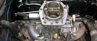
The next stage is setting up the starting system.
- Having dismantled the air filter, start the engine and immediately pull out the choke.
- After warming up a little, use a screwdriver to open the damper a third.
- We bend the damper rod so that the crankshaft speed reaches 3300 rpm.
- We tighten the adjusting screw for automatic opening of the damper so that the speed drops by 300 units.
The final stage for the VAZ 2107, or the fifth VAZ model, is setting the idle speed. It is produced like this. On a warm running engine.
- We unscrew the mixture composition screw, reaching the maximum crankshaft speed.
- Tighten the mixture quantity screw to reduce the speed to 1100 rpm.
- We tighten the mixture screw until the crankshaft speed drops to 800 rpm.
Adjusting the idle speed of the VAZ 2105 carburetor is done in a similar way. As for the “six”, almost the same DAAZ 2107-1107010-20 unit was installed there. Setting up this VAZ 2106 carburetor is carried out according to the instructions given above.
The principles for setting up the Solex carburetor of the VAZ 2109 differ little from those described earlier. The work requires the same tools; in fact, the main thing is to have:
- screwdriver;
- calipers.
Let's say all the preparatory manipulations have already been done. Let's proceed directly to setting up the device. We start with the float chamber.
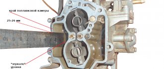
- After unscrewing the five screws, remove the assembly cover.
- Using a caliper, measure the distance between the edge of the body of the float chambers and the gasoline level of the chamber. The value should be 25.5 mm. If the size is not met, it is necessary to bend the tongue of the float bracket.
- Turn the drive and close the air damper.
- Having sunk the rod of the device with a screwdriver, we measure the gap between the chamber wall and the slightly open damper. We check compliance with the passport data of the assembly unit.
- If necessary, change the gap using the adjusting screw on the accelerator pump housing.
- Finally, with the choke closed, we measure the clearance of the throttle valve of the first chamber. If it does not correspond to the norm, rotate the throttle adjusting screw. This gap, for example, on a unit brand 2108 is 1 mm, and for a unit brand 21083 – 1.1 mm. Here we need to say, let’s say, the 2108 model was installed on the “eight” and “nine”, and the Solex 21083 was installed on the VAZ 21083 and VAZ 21093 cars. That is, everything depended on the engine size. Consequently, the adjustment of the VAZ 2108 carburetor is initially the same for both the Lada of the eighth model and the Lada of the ninth model.
However, based on the fact just noticed, for example, the carburetor adjustment on a VAZ 21083 will differ from the settings on a VAZ 2108 only in the nameplate clearance values. They can be found in the technical documents of the units.
The final operation when setting up a type 2108 carburetor will be setting the idle speed.
- Turn the mixture quality screw all the way.
- Then turn this regulator back 5 turns.
- The engine must be started, it must be at operating temperature with the choke off.
- By rotating the large black screw for the mixture amount, we achieve minimum crankshaft speed with stable engine operation.
- There should be a minimum vacuum inside the vacuum advance tube that can be felt by the tip of the tongue.
- Then we tighten the quality screw so that the engine begins to operate unstably. Then unscrew the screw one and a half turns until stable operation appears.
- Using the mixture quantity screw, we reach a crankshaft speed of 850 – 900 rpm.
- If the engine starts to stall, then slightly unscrew the mixture quality regulator.
On a 21083 carburetor, the idle speed adjustment is completely identical.
The main nuances of the procedure on UAZ
In order to get a complete understanding of the intricacies of tuning carburetor units, let’s also consider adjustments on the UAZ. Most of the units used with these machines were marked as K-151.
For this procedure you need to take:
- screwdriver;
- spanners;
- rubber bulb;
- ruler or caliper.
We perform the following actions.
- Set the required float chamber parameter. To do this, dismantle the cover and pump out a quarter of the fuel with a pear. Having pumped up gasoline, fill the chamber to the maximum level. When it stops filling, we take a measurement. The depth of the float chamber should be 21.5 mm.
- To set up the starting system, turn it on with the lever, start the engine, lightly press the gas pedal, and then use a screwdriver to open the choke. In this case, the crankshaft frequency should be equal to 2500 rpm according to the tachometer. If not, then it is adjusted with an adjusting screw.
- To adjust the idle speed of a hot engine, use the quality screw to bring the speed up to the most suitable speed - 950 rpm. Then use the quantity screw to add another 100 rpm. Then, on the contrary, we reduce the quality screw back to 900 rpm.
In general, it should be noted that it is no more difficult to repair and adjust this carburetor than to do the same with VAZ units.
Nuances of the work
The Ozone carburetor is adjusted when replacing elements of the device. If the guide handle is extended, the choke must be closed. In case of deviations from the norm, it will be necessary to lubricate the cable with engine oil. After this, rearrange the end of the cable in the damper block and unscrew the screw. The lever is completely lowered. At the same time, the air damper closes and the VAZ 2105 carburetor rod is located at the bottom of the rod groove. If the last element moves, it will be necessary to straighten the deformed parts by adjusting the length of the link.
How to disassemble a carburetor
If the air damper is completely closed, the throttle analogue of the 1st chamber should be slightly open by 0.8-0.9 mm. This indicator may change due to fluctuations in the bending of the rod. When the rod is moved inside the VAZ 2105 carburetor body all the way, the air damper opens slightly by 5.5 mm. The distance can be adjusted by unscrewing the cover screw. A similar block is installed under it, the rotation of which sets the gap. Once the cap is installed, the ozone carburetor adjustment is complete.
The carburetor needs to be adjusted only when the engine is warm. In this case, the suction button must be completely recessed.
At the factory, the procedure is performed at a minimum crankshaft speed of 850 rpm. In this case, the carbon monoxide content should be 0.05 g 2%. The bushings are pressed onto the screw heads. If you turn the bushings there is no way to restore the factory settings, the screws come loose and the bushings are broken. This will make the appropriate settings.
Repairing a VAZ 2105 carburetor: how to set up the injection system?
The fifth Lada model was produced from 1980 to 1995 and was in great demand. The main engine installed on these cars was a four-cylinder internal combustion engine with a displacement of 1.29, 1.45 or 1.57 liters. To prepare the combustible mixture for engine operation, domestic ozone carburetors and their modifications were installed. We will tell you how to adjust and repair a VAZ 2105 carburetor with your own hands.
First, let's take a closer look at the device itself, which mixes fuel with air in certain proportions. After mixing, the working mixture enters the engine cylinders and determines the normal operation of the unit in different modes. A carburetor is a rather complex and very precise unit, so the accurate implementation of the main functions depends on strict adherence to the parameters set at the factory and their subsequent adjustment.
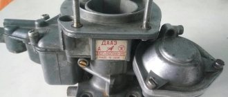
CARBURETOR 2105-1107010
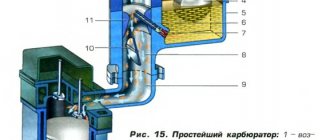
The VAZ-2105 car is equipped with a 2105-1107010 emulsion-type carburetor, two-chamber, with a falling flow. Has a balanced float chamber (Fig. 2-81),
Rice. 2-81. Diagram of the main dosing system of the carburetor and econostat (the econostat spray is located in the second chamber of the carburetor. In the diagram it is conventionally shown in the first chamber):
1 — econostat emulsion jet; 2 — emulsion channel of the econostat; 3 — air jet of the main dosing system; 4 — econostat air jet; 5 — econostat fuel jet; 6 — needle valve; 7 — float axis; 8 — locking needle ball; 9 — float; 10 - float chamber; 11 — main fuel jet; 12 - emulsion well; 13 - emulsion tube; 14 — axis of the throttle valve of the first chamber; 15 — spool groove; 16 — spool; 17 — large diffuser; 18 — small diffuser; 19 - sprayer
two main metering systems, an enrichment device (econostat) with a pneumatic drive, a crankcase gas suction system behind the throttle valve, a pipe for supplying vacuum to the vacuum regulator of the ignition distributor, an autonomous idle system with a forced idle economizer (Fig. 2-82) with electronic control by engine crankshaft rotation speed.
Rice. 2-82. Diagram of the carburetor idle system 2105-1107010:
1 — throttle body; 2 - throttle valve of the first chamber; 3 - holes for transition modes; 4 - adjustable hole; 5 - air supply channel; 6 — economizer needle; 7 — forced idle economizer housing; 8 - economizer cover; 9 — hose connecting the economizer to the pneumatic valve; 10 — adjusting screw for the amount of mixture; 11 - adjusting screw for the composition (quality) of the mixture; 12 — emulsion channel of the idle system; 13 — carburetor body cover; 14 - air damper; 15 — air jet of the idle system; 16 — fuel jet of the idle system; 17 — fuel channel of the idle system; 18 - emulsion well; 19 — pneumatic valve; 20 - hose going to the inlet pipe
The throttle valve of the second chamber has a pneumatic drive (Fig. 2-83), the air damper has a diaphragm starting device for starting a cold engine (Fig. 2-84). The accelerator pump (Fig. 2-85), a diaphragm type, mechanically driven, supplies fuel to the first chamber.
Rice. 2-83. Diagram of the carburetor throttle valve drive 2105-1107010:
1 — pneumatic drive jet located in the diffuser of the first chamber; 2 — throttle valve drive lever; 3 - lever rigidly connected to the axis of the throttle valve of the first chamber; 4 - lever limiting the opening of the throttle valve of the second chamber; 5 — pneumatic drive jet located in the diffuser of the second chamber; 6 - lever connected to lever 9 through a spring; 7 — axis of the throttle valve of the second chamber; 8 — pneumatic drive rod; 9 — throttle control lever of the second chamber; 10 — channel for supplying vacuum to the pneumatic drive; 11 - rod bushing; 12 — pneumatic drive of the throttle valve of the second chamber
Rice. 2-84. Carburetor trigger diagram 2105-1107010:
1 — air damper control lever; 2 - air damper; 3 — air pipe of the first chamber; 4 - traction; 5 — starting rod; 6 - diaphragm; 7 - adjusting screw; 8 - cavity communicating with the throttle space; 9 — telescopic rod; 10 — throttle valve drive lever; 11 — sector (antenna); 12 — axis of the throttle valve of the first chamber; 13 — lever on the axis of the throttle valve of the first chamber; 14 - lever connected to the air damper
Rice. 2-85. Carburetor accelerator pump diagram 2105-1107010:
1 — screw valve; 2 - sprayer; 3 - fuel channel; 4 - bypass jet; 5 - float chamber; 6 — accelerator pump drive sector; 7 — drive lever; 8 — return spring; 9 - diaphragm cup; 10 — pump diaphragm; 11 — inlet ball valve; 12 — pump vapor chamber
Carburetor calibration data is given in Table 2-6.
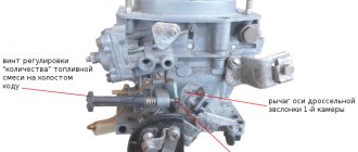
Adjusting the engine idle speed
Engine idle speed adjustment elements include screw 2 (Fig. 2-86), which determines the mixture composition, and screw 1, which regulates the amount of mixture.
Rice. 2-86. Carburetor idle speed adjustment screws 2105-1107010:
1 — mixture quantity screw; 2 - mixture quality screw
CARBURETOR CALIBRATION DATA 21-5-1107010
Table2-6
| Indicators | 1st camera | 2nd camera |
| Calibration number of the mixture sprayer | 3,5 | 4,5 |
| Diameter of the main fuel jet, mm | 1,07 | 1,62 |
| Diameter of the main air jet, mm | 1,70 | 1,70 |
| Emulsion tube calibration number | f15 | f 15 |
| Diameter of the idle fuel jet, mm | 0,50 | 0,60 — |
| Diameter of the idle air jet, mm | 1,70 | 0,70 |
| Diameter of the accelerator pump nozzle hole, mm | 0,40 | — |
| Accelerator pump bypass jet diameter | 0,40 | — |
| Accelerator pump performance for 10 full strokes, cubic cm. | 7 + 25% | |
| Econostat fuel jet diameter, mm | — | 1,50 |
| Econostat air jet diameter, mm | — | 1,20 |
| Diameter of the emulsion jet of the econostat, mm | — | 1,50 |
| Diameter of the pneumatic drive jet of the throttle valve of the second chamber, mm | 1,20 | 1,00 |
| Diameter of the air jet of the starting device, mm | 0,70 | — |
| Distance of the float from the carburetor cover with gasket, mm | 6,5 + 0,25 | |
To ensure that the owner does not violate the factory settings, restrictive plastic bushings are pressed onto the screws, allowing the screws to be turned only half a turn.
If it is not possible to adjust the CO content in the exhaust gases with the bushings, then by unscrewing the screws, break the heads of the bushings, unscrew the screws, remove the bushings from them and screw the screws back into the carburetor.
Note. Blue bushings are installed at the factory, and red bushings are installed at service stations.
Idle speed adjustment is carried out on a warm engine (coolant temperature 90 - 95 ° C and oil temperature 75 - 90 ° C) with adjusted gaps in the valve timing mechanism and with a correctly adjusted ignition timing.
Make adjustments in the following order:
- Using screw 1 (see Fig. 2-86), set the crankshaft rotation speed to 820 - 900 using the stand tachometer.
- use screw 2 to achieve a CO concentration (reduced to 20 ° C and 1013 GPa (760 mm Hg)) in the exhaust gases within 0.5 - 1.2% at a given position of screw 1;
- Use screw 1 to restore the crankshaft speed to 820 - 900 m
- if necessary, use screw 2 to restore the CO concentration to 0.5 - 1.2%;
- Press restrictive plastic bushings onto the screws, orienting the splines of the bushings relative to the mounting lugs, as shown in Fig. 2-87.
Rice. 2-87. Installation of restrictive bushings on the carburetor idle speed adjustment screws 2105-1107010;
a - on the screw for the amount of mixture; c - on the mixture quality screw
Setting the fuel level in the float chamber
The fuel level required for normal operation of the carburetor is ensured by the correct installation of serviceable elements of the shut-off device (Fig. 2-88).
Rice. 2-88. Setting the fuel level in the carburetor float chamber:
1 — carburetor cover; 2 — needle valve seat; 3 - emphasis; 4 - needle valve; 5 — locking needle ball; 6 — valve needle pull-out fork; 7 — float bracket; 8 - tongue; 9 - float; 10 - gasket
The distance between the float and gasket 10 adjacent to the carburetor cover (size A) should be 6.5 ± 0.25 mm; This size is adjusted by bending tongue 8. In this case, the supporting surface of the tongue must be perpendicular to the axis of the needle valve and must not have nicks or dents.
Perform inspection with caliber 67.8151.9505. Hold the housing cover vertically so that the tongue 8 of the float lightly touches the ball 5 of the needle valve 4 without recessing it.
Adjust the maximum float stroke of 8±0.25 mm by bending the stop 3. The valve needle pull-out fork 6 should not interfere with the free movement of the float.
When installing the carburetor cover, check that the float does not touch the walls of the float chamber.
Note. The float installation should always be checked when replacing a float or needle valve; In the latter case, the valve seal must also be replaced.
Adjusting the carburetor drive
With pedal 16 fully pressed (Fig. 2-89)
Rice. 2-89. Carburetor control drive 210501107010:
1 — air damper control rod handle; 2 and 17 - seals; 3 — air damper drive rod; 4 and 14 - return squads; 5 - return spring fastening screw; 6 — transverse thrust; 7 — intermediate lever; 8 — longitudinal thrust; 9 - rod fastening bracket; 10 — bracket for mounting the roller; 11 and 13 — levers; 12 - roller; 15 — lock washer; 16 - throttle control pedal
The throttle valve of the first chamber must be fully open and the throttle lever must not have additional travel. When the pedal is released, the throttle valve should be completely closed. If this is not the case, then the position of the pedal and the throttle valve can be coordinated by changing the length of rod 8, rolling or screwing its tip.
At the same time, check and, if necessary, adjust the length of rod 6. The center-to-center distance of its tips should be 80 mm.
Rod 3 of the air damper drive and its shell must be secured so that when handle 1 is fully extended, the damper is completely closed, and when the handle is recessed, it is completely open.
Removing and installing a carburetor on a car
Remove the air filter.
Disconnect rod 6 from the throttle drive lever (see Fig. 2-89) and return spring 4. Disconnect rod 3 of the air damper drive from the carburetor.
Disconnect the hoses from the carburetor. Close the end of the fuel supply hose with a plug to prevent fuel leakage.
Remove the carburetor. Close the inlet of the inlet pipe with a plug. Install the carburetor in reverse order. After installation, adjust the carburetor throttle valve drive, as well as the engine idle speed.
Disassembling the carburetor
Remove the return clamp 8 (Fig. 2-90). Undo the cotter pin and disconnect the connection rod with the three-arm lever 3 from the throttle lever of the first chamber.
Rice. 2-90. View of carburetor 2105-1107010 from the throttle valve drive side:
1 - air damper; 2 — starting device; 3 — three-arm air damper control lever; 4 — telescopic rod; 5 - microswitch; 6 — throttle valve drive lever; 7 - lever limiting the opening of the throttle valve of the second chamber; 8 — return spring; 9 — pneumatic drive rod; 10 — pneumatic drive of the throttle valve of the second chamber
Disconnect rod 9 of the pneumatic drive from the throttle valve drive lever of the second chamber.
Squeezing the telescopic rod spring 4, disconnect it from the three-arm lever 3.
After unscrewing the fastening screws, disconnect the cover with the gasket from the carburetor body, being careful not to damage it and the float.
After unscrewing the fastening screws, disconnect the throttle body from the carburetor body, being careful not to damage the adapter bushings of the carburetor fuel-air channels pressed into the body and the bushing sockets. Carefully remove the thermal insulation pad.
DISASSEMBLY OF THE CARBURETOR HOUSING COVER
Using a mandrel, carefully push the float 16 axis (Fig. 2-91) out of the racks (push it towards the rack with the cut) and remove the axis with smooth-nose pliers. Taking care not to damage the float tongues, remove it with needle valve 15.
Rice. 2-91. Carburetor cover parts 2105-1107010:
1 - adjusting screw; 2 — starting device cover; 3 - spring; 4 - diaphragm; 5 — diaphragm rod; 6 — starting device housing; 7 - telescopic rod; 8 — air damper axis; 9 - air damper; 10 — carburetor cover; 11 - gasket; 12 - filter; 13 — filter plug; 14 — needle valve seat; 15 — needle valve; 16 — float axis; 17 — float; 18 — gasket; 19 — starting device thrust,
Remove the gasket 11 of the cover, unscrew the seat 14 of the needle valve, unscrew the plug 13 and remove the fuel filter 12.
Disconnect the telescopic rod 7 and the rod 19 of the starter drive from the lever of the air damper axis 8.
Unscrew the two screws securing the housing 6 of the starting device and remove it.
Unscrew the three screws securing the device cover 2 and remove the cover with the adjusting screw 1 and spring 3. Remove the diaphragm 4.
DISASSEMBLY THE THROTTLE BODY (Fig. 2-92)
Rice. 2-92. Carburetor throttle body parts 2105-1107010:
1 — throttle valve drive lever; 2 - lever limiting the opening of the throttle valve of the second chamber; 3 - bushing; 4 — link lever with the air damper; 5 - lever mounted on the axis of the throttle valve of the second chamber; 6 - spring; 7 — lever connected to the pneumatic drive; 8 — throttle body; 9 — return spring of the first throttle valve; 10 — axis of the second throttle valve; 11 — throttle valves; 12 — axis of the first throttle valve; 13 — restrictive bushings; 14 — idle mixture adjustment screw; 15 - sealing ring; 16 — gasket; 17 — forced idle economizer housing; 18 — economizer cover; 19 — screw for adjusting the amount of idle mixture; 20 — economizer diaphragm; 21 — economizer needle; 22 — needle seat; 23 — microswitch mounting bracket; 24 - microswitch; 25 - spool; 26 — spool spring; 27 - lever mounted on the axis of the first throttle valve
Break the heads of the limiting bushings 13, unscrew the adjusting screws 14 and 19 and remove the remaining bushings.
Unscrew the screws and remove the forced idle economizer cover 18, diaphragm 20 with needle 21 , economizer body 17 and seat 22. At the same time, remove bracket 23 with microswitch 24.
Bend the lock washer's tendril and unscrew the nut securing the levers to the damper axis of the first chamber.
Remove the lock washer, levers 1,2,4,27 with washers and bushing 3 from the damper axis of the first chamber, and then the spool pressure spring 26 and spool 25.
Unscrew the nut securing the levers on the throttle valve axis of the second chamber, remove the levers with washers and spring.
DISASSEMBLY OF THE CARBURETOR HOUSING
Unscrew the two screws and remove the pneumatic actuator of the throttle valve of the second chamber. Unscrew the three screws securing the cover 4 (Fig. 2-93) of the pneumatic actuator and remove it, the spring and the diaphragm 3 with the rod.
Rice. 2-93. parts 2105-1107010:
1 — rod of the pneumatic drive of the second throttle valve; 2 - pneumatic drive housing; 3 - diaphragm; 4 — pneumatic drive cover; 5 — fuel jet of the transition system of the second chamber; 6 — fuel nozzle body; 7 — small diffuser of the second chamber; 8 — accelerator pump nozzle; 9 — screw valve of the accelerator pump; 10 — main air jet of the second chamber; 11 — emulsion tube of the second chamber; 12 — main air jet of the first chamber; 13 — emulsion tube of the first chamber; 14 - main fuel jet of the second chamber; 15 — main fuel jet of the first chamber; 16 — accelerator pump adjusting screw; 17 — fuel jet of the idle system; 18 — fuel nozzle body; 19 - return spring of the accelerator pump; 20 — accelerator pump diaphragm; 21 — accelerator pump cover; 22 — small diffuser of the first chamber; 23 — lever return spring; 24 — three-arm lever for air damper drive; 25 — connection rod with the throttle valve; 26 — bracket for the throttle valve return spring
Unscrew the screw securing the air damper control lever 24, remove the bracket 26, the lever and the spring 23, and disconnect the rod 25 from the lever.
Remove the screws securing the cover 21 of the accelerator pump with return spring 19.
Unscrew the main air jets 10 and 12, turn the body over and, lightly tapping it, shake out the emulsion tubes 11 and 13 from the wells.
Unscrew the housings of jets 6 and 18 and remove them together with jets 5 and 17.
Unscrew the valve-screw 9 and remove the accelerator pump nozzle 8 with gaskets, unscrew the accelerator pump adjusting screw 16.
Take out the small diffusers 7 and 22, unscrew the main fuel jets 14 and 15.
CLEANING AND CHECKING TECHNICAL CONDITION
Fuel filter. Wash the filter in gasoline and blow with compressed air. Check the condition of the filter and the conical sealing ring of the filter plug. If the filter or plug is damaged, replace it with a new one.
Float mechanism. Wash the parts in acetone or gasoline. The float must not be damaged or distorted in any way. The mass of the float should be 11 - 13 g. The sealing surfaces of the needle valve and its seat must not be damaged to impair the seal of the valve. The valve should move freely in its seat, and its ball should move freely and not hang up. Replace faulty parts with new ones.
Carburetor cover. Clean the cover and all holes and channels from dirt and oil. Wash the lid in gasoline or acetone and blow with compressed air. Inspect the sealing surfaces of the cover. If damage is found, replace the cover with a new one.
Starting device. Clean all parts of the starting device, rinse with gasoline and blow with compressed air. Inspect the parts, replace damaged ones.
Jets and emulsion tubes. Clean the jets and emulsion tubes from dirt and resinous deposits. Wash them with acetone or gasoline and blow with compressed air.
WARNING
It is not allowed to clean the jets with metal tools or wire, and also to wipe the jets and other parts of the carburetor with cotton wool, cloth or rags, as lint can clog the fuel-emulsion path.
If the blockage is severe, you can clean the jets with a soft wood needle moistened with acetone.
Carburetor body. Clean the housing from dirt and oil. Wash the housing and its channels with gasoline or acetone and blow with compressed air. If necessary, clean the channels and emulsion wells with special reamers. Inspect the sealing surfaces of the housing; if they are damaged, replace the housing with a new one.
Acceleration pump. Clean the pump parts, rinse them and blow them with compressed air. Check the ease of movement of the ball in the screw valve 9 (see, Fig. 2-93) and the condition of the sealing surfaces and gaskets.
Check the ease of movement of the moving parts of the pump (lever, roller, diaphragm parts). Jams are not allowed. The diaphragm must be intact, without deformation. Replace damaged parts with new ones.
Pneumatic drive of the throttle valve of the second chamber. Clean the parts, rinse and blow with compressed air. Check the condition of the diaphragm; it should not be damaged.
Throttle body and its parts. Clean the parts and rinse them with gasoline or acetone. Inspect the parts, replace damaged ones.
CARBURETOR ASSEMBLY
The carburetor is assembled in the reverse order of disassembly. In doing so, pay attention to the following:
• the float must rotate freely on its axis without touching the chamber walls;
• the needle valve should slide freely in its seat without distortion or jamming, and the valve guide should not interfere with the movement of the float tongue.
To avoid mixing up the jets of the first and second chambers during assembly, pay attention to the markings of the jets and when installing them, follow the calibration data table given at the beginning of the chapter.
The main air jets 3 (see Fig. 2-81) have a marking on the upper plane of the jet head (for example, “170”), which indicates the diameter of the jet hole (1.70 mm).
For main fuel jets, 11 numbers are printed on the side surface (“107”) and also indicate the diameter of the nozzle hole (1.07 mm).
The emulsion tubes 13 of the first and second chambers of the carburetor of this car are the same. However, they may be different on other car models. Therefore, on the cylindrical surface, at the bottom of the tubes, numbers are applied (for example, “F 15”), which indicate the calibration number of the tube.
On small diffusers 18 there are also numbers (for example, “4.5”) indicating the calibration number of the atomizer hole.
For idle fuel jets, numbers are stamped on a cylindrical band (for example, “50” or “60”) and indicate the hole diameter (0.50 or 0.60 mm).
Installation of the pneumatic drive of the throttle valve of the second chamber. Attach rod 8 (see Fig. 2-83) to lever 6 on the axis of the throttle valve of the second chamber in the following order:
• turn the throttle valve of the second chamber to a vertical position;
• press the rod 8 of the pneumatic actuator all the way and, holding the sleeve 11 from turning, turning the rod out or in, adjust its length so that the hole in the tip of the rod 8 is opposite the pin on the lever 6;
• put rod 8 on lever pin 6 and secure with lock washer;
• secure rod 8 with a locknut, holding bushing 11 from turning with another wrench.
ADJUSTING AND CHECKING THE CARBURETOR AFTER ASSEMBLY
Position of the throttle valves. The partial opening of the throttle valve of the first chamber, at which the upper tendril of lever 3 (Fig. 2-94a) comes into contact with lever 2, should be 6 ± 0.1 mm.
This size can be adjusted by bending the upper tendril of lever 3. Fig. 2-94. Adjusting the carburetor throttle valve positions 2105-1107010:
a - partial opening of the throttle valve of the first chamber; c - full opening of the throttle valves; 1 — lever on the throttle axis of the second chamber; 2 - lever limiting the opening of the throttle valve of the second chamber; 3 - lever rigidly connected to the axis of the throttle valve of the first chamber; 4 — damper drive lever; 5 — throttle valve of the first chamber; 6 - throttle valve of the second chamber
Full opening of the throttle valves is checked by turning their drive levers to the stop position. The maximum opening value of the throttle valve of the first chamber (13±0.5 mm) is adjusted by bending the lower tendril of lever 3.
The maximum opening value of the throttle valve of the second chamber (15±0.5 mm) is adjusted by screwing in or unscrewing the pneumatic drive rod.
The position of the microswitch is adjusted when the air damper is open.
Microswitch 3 (Fig. 2-95) should turn off when lever 2 is turned clockwise until it stops. When turning lever 2 from its original position counterclockwise until it stops at the antenna A of lever 1, the microswitch should turn on. Rice. 2-95. Adjusting the microswitch position:
1 - lever mounted on the axis of the throttle valve of the first chamber; 2 — throttle valve drive lever; 3 - microswitch; A - lever antenna 1
To adjust the moment of turning the microswitch on and off, loosen the screws securing it to the bracket and turn it relative to the top screw to the required position. Then tighten the mounting screws.
Starting device. When turning lever 1 (Fig. 2-96) counterclockwise until it stops, the air damper should be completely closed. Moreover, in this position of the lever, the end of the rod 3 should be at the end of the groove of the rod 4 of the starting device, but not move the rod. This requirement is met by bending rod 3.
Rice. 2-96. carburetor starter drive 2105-1107010:
1 — three-arm lever for air damper drive; 2 - air damper; 3 — thrust of the starting device; 4 - rod; 5 - adjusting screw; 6 — throttle valve of the first chamber; 7 — throttle drive rod
With the air damper completely closed, the throttle valve of the first chamber should be slightly open by 0.7-0.8 mm (gap C is the distance between the damper and the chamber wall at the location of the idle air system vias). This gap is adjusted by bending rod 7.
A fully closed air damper should be opened 5 (+0.5) mm (gap B) by the trigger rod when moving it manually to the right until it stops. This value is adjusted with screw 5.
The fuel supply by the accelerator pump is checked during ten full strokes (turns) of lever 4 (see Fig. 2-94) of the throttle valve drive. The fuel released from the pump nozzle during these ten strokes is collected in a beaker. Its volume should be 5.25-8.75 cc.
Before starting the test, make ten test strokes with the lever to fill the accelerator pump channels.
The tightness of the needle valve is checked on a stand, which supplies fuel to the carburetor at a pressure of 30 kPa (3 m of water column). After setting the fuel level in the test tube of the stand, it is not allowed to drop for 10-15 s. If the fuel level in the test tube decreases, this indicates a fuel leak through the needle valve.
CHECKING THE OPERATION OF THE FORCED IDLE ECONOMIZER
Checking the economizer. Check the operation of the economizer by disconnecting the wires from the pneumatic valve with the engine running. The engine should stall.
Check the tightness of the economizer diaphragm by supplying air at a pressure of 0.15 MPa (1.5 kgf/cm 2 ) into the economizer fitting. No pressure drop is allowed within 10 s.
Checking the pneumatic valve. Turn on the ignition and use a voltmeter or test lamp to check whether there is voltage at the pneumatic valve connectors. Check operation by disconnecting and reconnecting wires to the air valve plugs. When the valve is activated, a characteristic click should be heard.
Start the engine and disconnect the wires from the air valve. The engine should stall.
The valve must be sealed when air is supplied with an excess pressure of 0.085 MPa (0.85 kgf/cm 2 ) to the unmarked fitting or when a vacuum of 0.085 MPa (0.85 kgf/cm 2 ) is supplied to fitting “1”. Plug connector “2” when checking for leaks.
When a vacuum of 0.085 MPa (0.85 kgf/cm 2 ) is supplied to fitting “1”, the valve should open when an electric voltage of 12 V is supplied and close when the voltage is removed.
Current consumption at a voltage of 12 V is 0.375 A. Minimum operating voltage at a temperature from -40 to 100 ° C, a vacuum at fitting “1” of 0.085 MPa (0.85 kgf/sq. cm) or excess pressure at an unmarked fitting of 0.085 MPa (0.85 kgf/sq.cm), with closed fitting “2” there should be 9 V.
Checking the microswitch. Disconnect the wires from the microswitch and, using an ohmmeter or a test lamp with a power of no more than 5 W with a battery, check the operation of the microswitch by pressing and releasing its lever. When you press the lever, the microswitch contacts should open (the control lamp should go out). When the lever is free, the microswitch contacts must be closed (the control lamp is on).
Check the microswitch setting as above and adjust if necessary.
Checking the pneumatic valve control unit is described in the “Electrical Equipment” section.
>
Main parts
To perform its tasks, the VAZ 2105 carburetor consists of the following mechanisms and systems:
- Engine starting and heating system.
- Fuel level maintenance system.
- System XX (inactive);
- Econostat system.
- Acceleration pump.
- Basic dosing system.
There are three systems you can configure: these are the first on the list. The VAZ 2105 carburetor can be adjusted without disassembling the self-regulating device of the DaAZ 1111 carburetor Video! -. Due to the fact that the carburetors of the fifth and seventh models are identical in design and differ only in the diameter of the air and fuel jet holes, the carburetor on the VAZ 2107 can be adjusted in the same way.
The carburetor on any vehicle is one of the components of the fuel system of an internal combustion engine. It mixes air with a flammable liquid, and this mixture is supplied to the cylinders of the internal combustion engine. As you can see, this part of the car plays a very important role in the operation of the car as a whole. Therefore, the carburetor must be adjusted periodically. You will learn how to do this correctly on a VAZ-2105 from this article.
Cold start system
The DAAZ-2105 carburetor starts working from the starting system. Using the choke lever, the channel is closed, and the throttle valve is slightly opened to a certain clearance.
At the same time, the engine receives the richest possible mixture - it is supplied from the float chamber through the jets of the main metering system and the small diffuser. Then the engine starts. To prevent a large amount of liquid fuel from entering the cylinders, the vacuum actuates the starting device membrane and the air damper opens slightly.
Nuances of the VAZ-2105 carburetor adjustment process
Experts immediately warn inexperienced motorists: if you don’t know where the carburetor is located in the car and what it consists of, you shouldn’t even start making adjustments. You can disable the entire car by incorrectly changing the parameters of the fuel system. It is best to entrust this procedure to qualified mechanics from the workshop.
So, to begin adjusting the carburetor of a specific car model, you need to study its structure. So, the VAZ-2105 carburetor contains several important systems:
- dosage;
- starting and warming up the engine;
- maintain an optimal fuel fluid level;
- idle start;
- economist's system;
- accelerator pump.
Three of all listed systems are subject to standard settings:
- Starting and warming up the internal combustion engine (the starter is configured).
- Maintaining the fuel fluid level (adjustable float mechanism).
- Minimum (the number of revolutions is calibrated using a special screw).
To install them, it is absolutely not necessary to remove the carburetor device from the car.
The first stage is setting up the float mechanism of the VAZ-2105 carburetor
The first step in adjusting the carburetor float mechanism is to allow the vehicle to idle. And only after that proceed to the setup procedure.
- The carburetor cover is removed.
- The current level of fuel fluid in the chamber of the float mechanism is checked (its digital indicator should ideally be 28 mm).
If the digital fuel level indicator in the float chamber is OK, there is no need to adjust anything. Otherwise, follow these steps:
- check the distance from the cover gasket and from the float itself (this is done at the moment the needle valve ball comes into contact with it) - the norm is 6.5 mm (+ - 0.25 mm);
- fold your tongue;
- check the maximum stroke of the valve needle - the norm is 8 mm;
- check the distance between the cover gasket and the maximum retracted float - the norm is 14 mm (+ - 0.5 mm).
If the indicators do not meet standard standards, they can be adjusted using a bracket. If after adjustment it is not possible to achieve the optimal level of fuel fluid in the reservoir, the needle valve must be replaced.
Why does the cylinders flood?
Also look carefully at the spark plugs; if they have heavy carbon deposits on them, the engine will run unstably. But if a lot of gasoline enters the combustion chambers, then most likely it is necessary to adjust the level in the float chamber. How to adjust the level will be discussed a little below. The saddest thing is if the reason that the cylinders are flooded is a burnt out valve.
In this case, the cylinder head will have to be repaired. If the engine runs unstable, as well as stops at high speeds, look for a fault first of all not in the carburetor, but in the fuel pump and its drive. But you need to look at the carburetor of the VAZ 2105; adjustment will not hurt it.
The second stage - we adjust the starting device of the VAZ-2105 carburetor
At this stage, in the garage, the motorist can configure the carburetor system, which starts and warms up the engine:
- close the air damper (this is done using the handle located inside the car);
- check the position of the end of the rod, which must be at the end of the groove in the carburetor rod to start the system;
- measure the gap level from the edge of the damper to the chamber wall (measurements are taken when the rod is recessed) - the norm is 5-5.5 mm.
If the digital indicators differ from the established standards, they are adjusted by turning a special adjusting screw (located on the carburetor starter).
Setting the needle valve opening
Turn the carburetor cap over so that it is positioned vertically. In this case, the tail of the float should lightly touch the needle ball. Please note that even partial overlap is not allowed. Measure the distance using a paper template. Determine the distance from the plane of the float to the gasket on the carburetor cover. It should be no more than 6.5 mm. If it is larger or smaller, then adjust in the desired direction by bending the small tail on the float. The distance to the maximum degree of valve opening is measured in the same way.
Third stage - idle speed adjustment
This stage is no less important than the previous two. To do this, the internal combustion engine is pre-started and warmed up. Only after this can the idle speed be adjusted.
- The engine is pulled out by rotational movements of the screw, the amount of mixture is a rotation speed of 850 rpm:
- to increase the speed, you need to turn the mixture quality screw (to maximum);
- to reduce the speed you need to turn the screw to the number (to the desired level 850).
- Tighten the quality screw to the maximum (rotational movements are carried out until the motor stops shaking).
- Unscrew the same screw in the opposite direction three turns.
In this way, the VAZ-2105 carburetor is adjusted to idle. All of the above actions by a mechanic are called idle speed calibration.
Device
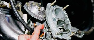
The DAAZ carburetor, developed by analogy with the product of the Italian brand Weber, is designed to dose the gas-air mixture in all engine operating modes without the participation of electronics. It consists of three main parts:
- covers with semi-automatic starting system;
- main or middle block with camera;
- additional or lower block with throttle valves.
The device cover includes important parts of the carburetor: flaps, a fitting for connecting a gasoline supply hose, a filter mesh, a needle float, an econostat tube, and an accelerator pump. The upper part of the carb is connected to the main block using several screws (M5).
The middle block consists of the main chamber, diffusers, jets, and a sprayer (helicopter). All the necessary channels responsible for certain engine operating modes are installed here.
The lower or additional block is equipped with throttles and adjusting screws, thanks to which it is possible to adjust the quality and quantity of the sprayed combustible mixture. There are also many different output channels available here. Like the upper part, it is connected to the main unit via screws.
It is easier to consider the carburetor design by looking at the operation of individual subsystems:
- A special place in the carburetor is occupied by the starting device system or SPU. It comes into operation when the engine starts. It is activated due to the vacuum created as a result of the movement of the cable when the diffuser opens. The SPU closely interacts with the gas pedal;
- Idle system. Its functions are clear by its name. On Weber it is of the classic type, on Ozone it is autonomous and works independently of the carburetor. On standard systems there is a special calibration screw that adjusts the throttle or air. It makes it possible to increase or decrease the number of idle speeds. There is also a mixture quality screw located in a different place, in a recess. By rotating it, you can supply the engine with exactly the amount of gasoline it needs;
- A transition system responsible for a smooth transition from idle to operation of the main jets. There is also a separate jet, which can also be attributed to this system. It stabilizes engine operation at high speeds;
- Main metering system based on the operation of the emulsion tube, fuel nozzle and chokes. It is in this mode that it is possible to open both throttles and the maximum speed of the car;
- Accelerator pump system. It controls the mixture, preventing air from entering more than normal. This makes it possible to avoid throttle failures during sudden car starts from a standstill and other maneuvers;
- Econostat that increases engine thrust at maximum speed. Consists of three jets: fuel, emulsion and air;
- A float mechanism system that maintains a constant fuel level in the chamber. Equipped with an adjustable needle valve. When the fuel in the chamber decreases, the float moves down, the valve opens and gasoline from the tank begins to flow through the fitting.
Expert advice
In the area of the procedure for adjusting the VAZ-2105 carburetor device, experienced mechanics recommend paying attention to the following critical points:
- The valve seat is in the retracted position and the idle jet is touching the seat in the carburetor body.
- Lubricate the rubber seal with special engine oil.
- The position of the air damper intended for cold passage is in a vertical plane, while the air handle is lowered.
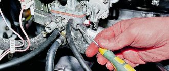
- The condition of the solenoid valve - damage and malfunctions is checked as follows:
- turn on the ignition;
- remove and put the connector on the valve;
- listen for sounds coming from the solenoid valve.
If clicks are heard during inspection, it means the part is in good condition.
Dampers
Primary adjustment comes down to adjusting the cable on the trigger mechanism and adjusting the accelerator pedal traction. It is easy to adjust the thrust - the plastic tip is placed approximately opposite the hinge, twisting it along the thread. To secure, tighten the nut 10 mm.
The choke drive cable is adjusted as follows. The choke lever in the cabin is pushed in all the way, and the air damper must be fully open. The cable is threaded through the eyes, and the end is inserted into the corresponding hole in the clamp. While holding the latch, tighten the bolt with a wrench. When pulling and retracting the choke, you need to make sure that the damper opens and closes completely.
Next, check how the throttle of the second chamber opens. The membrane and rod must be in such a state that their stroke is sufficient to fully open the damper. If the stroke is not enough, then unscrew the nut that is on the rod and adjust the length.