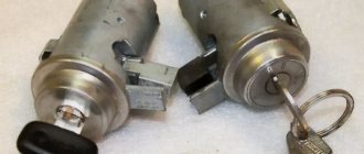
Experts recommend choosing the latter option; in this case, you will be able to control the temperature at the radiator outlet. And the threads can rust and stick, and the cross-shaped slots of the screws can also rust. The left side is lowered first, then the block is moved to the left, raising the right edge so that the casing becomes vertical. The cooling system fan does not turn on on a fuel-injected car. What is the reason.
Well, for example, you are crossing a ford, and at that moment the fans work, or they work at the moment when you decide to dive, what can happen? It may happen that when you buy fans, they will not have rubber gaskets on their supports that dampen vibrations. Not available, for the year of manufacture either. In addition, the radiator tap is equipped with an O-ring.
Make sure that the drill does not jam or break; it has never broken. I've been driving this way for almost two years now.
When switching manually, you need to install a switch; a key is best suited, and for automatic control, an additional switching sensor with a response temperature lower than the main one. Installing an electric cooling radiator fan on a VAZ 2106 (classic)
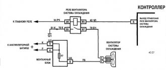
How does the Niva fan connection diagram described above work?
When the engine temperature reaches the low temperature sensor response threshold, the relay to which it is connected will operate.
In this case, the current from the fuse through the relay contacts will flow to the positive brush of the first fan. Then passing through the armature winding to the negative brush and through the contacts of the additional relay to the second fan motor. At the electric motor collectors there will be ½ of the on-board network voltage. This will lead to a reduction in speed by half, and accordingly the noise will decrease. If the engine temperature reaches the response threshold of the second sensor or the temperature at which the ECU fans turn on, the additional relay coils and the second fan relay will receive power. The movable contact of the additional relay will switch the wire from the fan motor to vehicle ground, at the same time the second fan relay will close. This will cause the fans to be switched in parallel.
“If you notice an error in the text, please highlight this place with the mouse and press CTRL+ENTER”
admin 05/09/2015
The VAZ-21214 engine cooling system is designed for off-road driving, that is, to operate for a long time at low speed and high revs. This causes the engine to become very hot. Therefore, the Nivas are equipped with a cooling radiator slightly larger than on the classics and two cooling fans.
In fact, the machines are operated mainly in urban environments, where the engine operates without overload and the operation of two fans to cool the radiator is practically not needed. In addition, when operating, the Niva cooling fan makes quite a bit of noise, which affects comfort.
Useful video
Connection diagram for the electric motor of the stove fan Niva 21213
VAZ-2121, 21213-15, 2129-31 are a famous family of SUVs that have gained enormous popularity from the first day the production model appeared in 1977. The VAZ-2121 Niva is a basic model, which is based on a monocoque three-door station wagon and a transmission with permanent all-wheel drive.
During the production of this car, many different modifications were designed and manufactured regarding the body structure, appearance, engine used and many other elements of the car. For example, the VAZ-21213 “Taiga” is a redesigned restyled version of the base car, the VAZ-21214 is a model with a domestic 1.7-liter engine, and the VAZ-21215 was equipped with the French Peugeot XUD 9SD engine. A special place is occupied by specimens converted for commercial use. In particular, the VAZ-2129 “Utility” is a model extended by 500 mm with two front seats and a cargo body, and the VAZ-2131 is an extended five-door station wagon.
Due to the huge number of modifications, it is difficult to talk about a specific group of spare parts that are in greatest demand. However, it should be noted that for many years there has been a steady interest in the details of the classic basic version of the Niva.
Source
Possible reasons
Fuses and relays Niva 21214 injector
Before repairing or replacing the cooling fan on a Chevrolet Niva, it is necessary, as already noted, to understand the reasons why this problem could occur. The first step is to inspect the front panel fuse. As a rule, it is located in the mounting block, on the passenger seat side. Two fuses take part in the air cooling process. At the same time, if the right one breaks down, both stop functioning, and if the left one breaks down, the right one still works.
The mounting block contains three relays. Each of them is responsible for a different speed of the cooling fan. If the low speed relay burns out, then the fan only works at maximum power. At the same time, by setting it to a low speed, it will heat up. There is also another additional fuse in the car that supplies power to the relay. If it malfunctions, the entire system will fail completely.
If the temperature sensor breaks, the cooling fan will also not work. Such sensors are installed directly on the engine itself. The first one comes into operation when the air temperature reaches 90 °C, and the second - at 101 °C. When diagnosing a fan failure, most often the inspection begins with them. To do this, you need to disconnect the connector from the electric motor and supply power to them through the battery. If the electric motor eventually starts, the sensors have failed.
If, as a result of checking the fuse, sensor and relay, no damage is detected, then proceed to inspecting the fans themselves. When checking them, their motor connectors are disconnected, and the voltage supply wires are connected to the lamp. We do the same scheme with the sensor. If the lamps end up glowing, then the fans are undoubtedly broken.
If the temperature in the engine compartment is too high, the plastic fan casings become deformed. If you start the fan in this state, its blades will begin to cling to the casing, which can cause the blade to heat up and subsequently melt. If you turn off the system after they melt, they will stick to the casing and will not start at all in the future.
Another very common problem is cold antifreeze. If there is cold antifreeze in the system and the ignition is already started, then the fans simply will not work. Most often this problem occurs due to:
- failure of the ECM controller;
- stuck fan relay contacts;
- loss of contacts of the pads or wiring harness that go to the controller from the temperature sensor.
Removing idle fans is very simple and quick:
- all wires are disconnected;
- the upper pipes are removed;
- the bumper is pulled out;
- if there is an air conditioner, the tubes are carefully removed, the freon is drained (the material is not cheap, so it is better to collect it in a clean container in order to later return it to its place);
- the air conditioning radiator is removed;
- the fastenings on the radiator casing become loose;
- the cooling fan unit is removed from the radiator at an angle;
- the bolts securing the block are disconnected, after which it is pulled out.
Operating principle
Radiator fan switching diagram for VAZ 2108, 2109, 21099
The Niva's cooling circuit operates under pressure, since in normal mode it does not communicate with the atmosphere. The coolant is antifreeze with a freezing point of -40 °C. It is a solution of water with ethylene glycol, the amount to fill the system is 10.7 liters. It also boils at an elevated temperature, +110 °C.
The key element in the operation of the system is the thermostatic valve, which distributes fluid flows depending on the heating of the engine. Inside the thermostat there is a damper controlled by a temperature-sensitive element. When heated, it moves the damper, opening another path for the flow. In general, the scheme works according to the following algorithm:
- When the engine is not warmed up to operating temperature (90 ° C), antifreeze, stimulated by the pump, circulates through a small cooling circuit: engine, thermostat, interior heater radiator.
- When the power unit heats up, the thermostat damper begins to open slightly, allowing part of the liquid to flow into the large circuit into which the main radiator enters. The movement of the damper begins at a temperature of about 80 °C, and when it reaches 92-94 °C it is completely open. Almost all the antifreeze now moves in a large circle, cooling in the main radiator.
- The small circulation ring does not close, because the stove must also function. But much less liquid flows there due to the small diameters of the pipes. The carburetor or throttle valve heating is connected to the same line.
- On the Niva VAZ-2121, the fan is installed on the axis of the water pump and constantly drives air onto the cylinder block. In the VAZ-21214 and 2131 models, 2 electric fans are turned on alternately or together, obeying the command of the controller, which is guided by the readings of the temperature sensor. The switching threshold is approximately 100 °C.
- The excess volume of antifreeze that occurs during heating goes through the hose into the expansion tank. At the same time, the pressure in the system increases, which makes it even more difficult for the liquid to boil. When cooling, the reverse process occurs: antifreeze returns to the system.
In the summer and transition period in VAZ-21213 and 21214 cars, the passage of coolant through the heater radiator is limited by a tap. There is no such tap on the Chevrolet Niva; the heating is turned off by redirecting the air flow past the heat exchanger.
Fan malfunctions
Let's look at what malfunctions of the Niva cooling fan may occur and how to identify them. The most common malfunction is blown fuses.
The fuse blows.
A single occurrence of such a malfunction does not indicate a faulty wiring or the fans themselves. During operation, fuses heat up and eventually fail. They are easy enough to replace. They are located on a carburetor car in the lower fuse block, and on an injection car in an additional block near the driver's door pillar.
If the fuses blow immediately when the fans are turned on, then it is necessary to find a short circuit or replace the fan. To determine the location of the malfunction, it is enough to disconnect the connector on the fan motor and connect the wires on the radiator sensor with each other with the ignition on.
On an injection engine, to check it is necessary to remove the chip from the temperature sensor, which is located on the thermostat. In this case, the engine control unit will go into emergency mode and activate a program for working with a faulty temperature sensor and turn on the fan relay. If the fuse burns out, then it is necessary to find and eliminate the short circuit. If the fuse remains intact, then the problem is most likely in the fan motor. Faulty fans are stuck or difficult to rotate. This may be caused by the stator magnet falling off or the armature bushings wearing out. A faulty fan should be replaced.
The fan does not turn on
Another common malfunction is when the fan does not turn on when the operating temperature is reached. The reason may be a malfunction of the fan sensor on a carburetor car or the engine control unit on an injection car, a relay malfunction, broken wires, or a malfunction of the fan motor.
It is better to start troubleshooting by checking the temperature sensor or control unit. This is done as described earlier by bridging the wires on the carburetor engine sensor or removing the chip from the temperature sensor on the injection engine. If the fans do not work, then you need to check the power relay.
The relays are located under the instrument panel on the front wall. To check, remove the chip from the relay and check for the presence of power at pins 30 and 85. If there is no power, check the condition of the fuse and wires. If there is power, connect terminals 84 and 85 of the relay with a test lamp. If the warning lamp does not light up, then the wire from the ECU connector to the relay socket is broken or the ECU itself is faulty. A lit lamp indicates a relay malfunction.
To test the relay, connect pins 87 and 30 with a piece of copper wire, which should trigger the fans. If this does not happen, then connect a test lamp to the connector without removing the jumper from the relay connector. If the lamp does not light up, then connect one end of the test lamp to the housing, and with the other, check for the presence of a plus on the connector. If the control lamp does not light up, then there is a break in the wire from the relay to the fan connector. Accordingly, the glow of the lamp indicates poor contact of the negative wire with the body or a wire break. The presence of power and minus indicates a malfunction of the electric motor.
The lifespan of a Niva SUV engine largely depends on how efficiently the VAZ-2121 cooling works. After all, overheating is the first enemy of the power unit, leading to expensive repairs.
This is why the serviceability of the components and elements of the cooling circuit is so important. In order to be able to service them and identify malfunctions, you need to understand what the circuit consists of and how the Niva’s cooling functions.
Replacing fans
If the fan motors do not start when the wires from the battery are connected directly to the power terminals, the devices must be replaced.
To do this, you will need a set of wrenches ranging in size from 10 to 17 mm and a Phillips screwdriver.
Before starting work, you need to drive the car onto an inspection ditch or a lift and turn off the power to the on-board network by removing the negative terminal of the battery.
Fans are dismantled as follows:
- Remove the crankcase protection and mud guard.
- Unscrew the screws and remove the thick spider-shaped plate and a couple of tin covers that are located in front under the bottom of the car.
- Unscrew the radiator frame cross member.
- Loosen the tension and remove the power steering belt and pump.
- Remove the 4 bolts holding the power steering pump.
Important: to get to the bolt covered by the oil filter, you need to move the amplifier away from the bracket.
- Push the pump back, hanging it on the hoses.
- Remove the air conditioner drive belt.
- Remove the bolt holding the timing belt pulley.
- Remove the pulley and belt.
- Unscrew the four nuts at the corners of the electric fan housing and the two bolts securing it in the middle.
- Remove the fan unit from the studs and pull it down.
Tip: The crankshaft position sensor makes it difficult to remove the fans. Therefore, they need to be pulled out gradually. The left side is lowered first, then the block is moved to the left, raising the right edge so that the casing becomes vertical.
This method is probably suitable for restyled Niva Chevrolet models. On older cars, you will have to remove the radiator grille and bumper, unscrew the fasteners and move the air conditioning and cooling radiators forward. After this, access to the electric fans will be open.
During dismantling, you should carefully remember the procedure. Assembly is carried out in reverse order.
Important: the service life of the fan motors is approximately the same. Therefore, even if one of them fails, both must be replaced. Otherwise, you will soon have to repair the car again.
How do fans work on a Chevrolet Niva?
How do fans work on a Chevrolet Niva?
Tips for motorists
The favorable thermal regime of the Chevrolet Niva SUV engine is supported by a cooling system, in which two serviceable fans play a significant role, providing the required air flow through the radiator core. If the fans fail, the cooling system cannot cope with removing excess heat from the engine, and it begins to overheat. Due to the fact that the number of fans on the Chevrolet Niva has been doubled, the electrical circuit for turning them on has become more complex than on conventional passenger cars.
If the temperature gauge needle is near the red part of its scale, and the system fans do not turn on, then you will have to stop and start searching for this malfunction. To do this, you will need to remove the cover of the additional mounting block located under the front panel (below the glove compartment) in the area where the front passenger's feet are located. There are two fuses protecting the electrical circuits of the fan motors. If the fuse protecting the circuit of the right electric motor blows, both fans will not turn on, and if the second blows, only the left fan will not turn on.
In the same block, there are three relays that are responsible for turning on the right fan at low and high rotation speeds and turning on the left fan at high rotation speed. The additional relay should operate when a control signal is applied to its terminal No. 86 from terminal No. 46 (ECM). In this case, voltage will be supplied to the fan motor terminals through a resistor. If the resistor burns out or this relay fails, the low speed fan will not work.
Fans on Niva Chevrolet
Hi all! Like, subscribe to the channel and tell your friends. There are many more interesting things.
The right fan relay is activated when a control signal is received at its terminal No. 86 from control terminal No. 6 (ECM). In this case, the fan should start operating at high rotation speed. If there is no control signal or this relay is faulty, the right fan will not turn on. The same control signal also turns on the left fan, since there is a jumper between terminals No. 86 and No. 85 of the right and left fan relays. But power to the left fan motor goes through its own fuse.
Also, both fans will not turn on if the coolant temperature sensor (CTS) fails. Since it is based on his data on the temperature of the antifreeze that the controller’s decision to turn on or not turn on the fans depends.
Due to the increased temperature inside the engine compartment, there are cases of deformation of the plastic fan casings, and when they are turned on, the rotating fan blades touch the casing. As a result, the tips of the blades are heated to their melting temperature. When the fans are turned off, the blades are welded to the casing and the next time they are turned on they will not work.
Another possible problem is that the fans start working immediately after the ignition is turned on, when the antifreeze in the engine cooling system is still cold. This happens for the following reasons:
- loss of contact on the block or in the wiring harness going from the coolant temperature sensor to the ECM, because if you remove the connector from this sensor, then if the electrical circuits of the fans are working, they should both work;
- “glitch” (malfunction) of the ECM controller;
- sticking contacts of the fan relay (but the likelihood of sticking contacts on three relays at once is very small);
Possible malfunctions and their causes
1.Both fans do not work. The electric motors may fail, the temperature sensor may malfunction, or the power wires coming from the battery or ignition switch may be broken.
2. The second fan does not work. Causes: sensor malfunction, fuse or electromagnetic relay failure. It is also possible that the power cable may be broken.
3. The left fan does not turn on. Causes: faulty power resistor or temperature sensor, blown fuse or relay. It is also possible that the power cable may be broken.
4. Only two fans turn on at a time. This happens when an additional resistor in the circuit of the first electric motor breaks.
5. The fan does not turn off. Typically, the fan runs constantly when the relay is broken or the coolant temperature sensor is faulty.
Methods for connecting fans.
The temperature rose, the fans turned on, everything was simple. Pull the wire back together with the bundle.
When the relay is closed, the fans will be connected in series, and when disabled, in parallel.
Compiled from the experience of installing them in 2 cars. After this, connect the free terminals on the motors with a wire of the appropriate cross-section.
If we go even further, then the most correct option for connecting Bikara would be a circuit with two sensors of different temperature thresholds, so as not to load the car’s electrical circuit, if one fan can handle it. APS status indicator. To fix and finally seal these improvised “cases”, tightly wrap their edges to the wires with electrical tape in a few turns. Current passes through the inductor, resulting in an electromagnetic field.
New cooling fan switching scheme
We take out any plug you like on the “beard”; I pulled out the far right one, take a piece of wire, insert it into the hole formed and with your right hand move the wire at an angle to the left, towards the edge of the “beard” located under the torpedo. Windshield wiper motor. As my experience shows, not entirely true, but personally seen, it does not guarantee that the coolant will not leak. Whoever has these supply pipes laid, pull out the rings.
This is caused by the engine working under heavy loads when driving off-road. Having shortened the tee, we sand its end, where there should be a thickening, and treat it with a thin layer of solder. Starter There is no great need for them. And it’s very simple.
AUTO ELECTRICIAN
It turns out that we need three fan operating positions: 1. In the factory firmware, the temperature for turning on fan 2 is degrees. Rear window wiper motor.
Pin 86 is connected to the ground of the car. Do not rely on the copper sealing washer included with the sensor. Relay for turning on the heated rear window. Then we take and connect the wires to the sensor. Automotive relay. How does it work? What is it for? How to connect?
Fan relay
The additional block contains not only fuses. There are also three electromagnetic relays that control the operation of the electric motors of the cooling system. Their control circuits are powered from the ignition switch and on-board controller outputs, and the power current comes from the battery through fuses.
The relay operates as follows:
- Voltage is applied to the control terminals.
- Current passes through the inductor, resulting in an electromagnetic field.
- The steel contacts attract and close.
- The current passing through the relay drives the electric motor.
As soon as the control voltage disappears, the contacts open under the influence of the spring and the fan stops.
You can check the functionality of the relay in three ways:
- Replace the relay with a known working one and test the operation of the system.
- With the engine off and the ignition on, disconnect the temperature sensor connector. You should hear the relay click.
- Dismantle and test the output contacts with a multimeter, applying voltage to the terminals of the induction coil.
Difference in fan connection diagram.
Doesn't touch anything anywhere
It is important that they wear evenly. The initial diameter of the left hole is 6 mm, and the diameter of the leg, more precisely, the rubber band put on the leg, is 15 mm. Let's look at the diagram Connecting Niva fans in a serial connection. The investment is cheap, but the effect is simply amazing, it’s a pity the designers at the factory didn’t think of this before
Assembly is carried out in reverse order. After this, the frame with the fans more or less normally falls into place. When removing the radiator trim, it may be that unless precautions have previously been taken to protect the screws that secure it from rust, it will be very difficult, if not impossible, to remove these screws. You can, of course, tighten the clamps as hard as you can, but as Murphy’s law says: “Everything that can go bad, goes bad,” and where is the guarantee that the pipe will not one day take or even fall off the tee? True, if something happens, with the latter it will be more difficult to unscrew the sensor back.
Heater electric motor. I had to add a third relay. When the temperature sensor is triggered, the second fan is also connected.
A useful video that shows how to remove and change fans: Important: to get to the bolt covered by the oil filter, you need to move the amplifier away from the bracket. VAZ oxygen sensor
Section: Electrical Post navigation.
Therefore, they need to be pulled out gradually. The fan does not turn off. When turned on, fans create some discomfort as they make noise. There are three rubber bands included. Well, then you can start installing the wiring. Venty on Niva 2121
Popular materials
Not available, for the year of manufacture either. The fans will turn on only based on the sensor signal. Tip: The crankshaft position sensor makes it difficult to remove the fans. Starter From the chip connected to one of the fans, we remove the negative wire; it is usually black. But in this case, in order to turn on the fans at high speeds, you will need to redo everything back. The most popular are electric-driven fans, which consist of an electric motor, an electronic control unit, a temperature sensor and a fan switch relay. Crankshaft position sensor. Except for the tee. Let's look at the diagram Connecting Niva fans in a serial connection. Injection system fuse box. We drag the harness over the steering column and move a piece of hose along it so that its middle is above the steering shaft. Distributor NIVA. Control of transfer case levers in all modes. Practice. Differentials NIVA 1h
More on the topic: Energy inspection of a building
Selecting an additional fan.
Before you start installing the element, there are a few things to consider:
- Before installation, you will need to remove the radiator, regardless of the location of the additional fan, since it will interfere.
- To work, you will need to purchase a tee from a GAZelle car, and you can find several options for this device on the market. A short tee is not suitable due to the small size and diameter of the pipes; a long tee will have to be shortened. The most sensible solution is to find the middle tee.
- When choosing a temperature sensor, the TM-108 model is suitable (it is also installed on VAZ-03, 07, GAZ-3102, 3110). Before installation, the sensor thread is lubricated with a sealing agent: the standard washer does not provide complete protection against leaks.
Vehicle cooling network design
The cooling system of the VAZ Niva is quite effective and has undergone virtually no changes since its creation. It includes the following units and elements:
- Mechanical water pump (pump). Installed in the cylinder block on the front side, its impeller is immersed in coolant circulating through the water jacket of the VAZ-2121 engine. Driven by belt drive.
- Mechanical thermostatic element (thermostat). It is located on the right side of the block in the direction of travel. From it the pipes go to the water jacket and radiator.
- Cooling radiator with 2 plastic tanks on the sides. Located at the front of the car.
- Fan with air diffuser. Attached to the inside of the radiator.
- Expansion plastic tank with a lid equipped with valves. Connected by a pipe to the radiator.
- Interior heater heat exchanger equipped with a tap.
Temperature control in the Niva engine cooling network is carried out in different ways. In the carburetor model VAZ-21213, a sensor is built into the cylinder head, connected to the temperature indicator on the dashboard. On the VAZ-21214 model, where the fuel is supplied by an injector, there is a second sensor mounted in the pipe on the cylinder head. It is connected to a controller that prepares the fuel mixture depending on the heating of the power unit and turns on the fans.
There are 2 more differences in the cooling design of engines with a carburetor and an injector:
- on cars with direct fuel injection, 2 electric fans are installed on the radiator instead of 1 mechanical;
- The heating pipes for the lower part of the carburetor in model 21214 provide heating for the throttle body.
In VAZ-2131 Chevrolet Niva cars, the cooling system is generally similar to a regular Niva with an injector. The VAZ-2131 heater radiator is not equipped with a tap, which is why antifreeze flows through it all year round.
Methods for installing electric fans on a classic Niva (VAZ 2121)
On the classic Niva, the standard cooling system is far from perfect and in modern road conditions (idles in numerous traffic jams and other stressful conditions) simply cannot cope with its responsibilities. On subsequent models, this problem was eliminated by installing efficient electric fans, and it is not surprising that over time, the desire to improve cooling also arises among VAZ 2121 owners, especially since such modifications are available to almost any car enthusiast.
Design and principle of operation
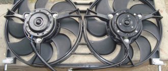
The designers of the Chevrolet Niva used a dual fan unit in the cooling system. This slightly complicated the connection diagram, but sharply increased the efficiency of radiator airflow. The fans are driven by 12-volt DC synchronous motors with a permanent magnet inductor. Electric motors have a closed, non-demountable design and do not require maintenance.
The power of each electric motor is 110 W. The fan assembly draws 18 amps.
The fans are turned on one by one using an electromagnetic relay controlled by the on-board computer. When the coolant heats up above 99 degrees, the electric fan located closer to the engine air intake starts. The switch-on temperature of the second impeller is 101 degrees. The fan connection diagram is shown below.
The fan power system includes three relays and a resistor, which, if necessary, provides a reduced rotation speed of the first motor. Power is supplied from the battery through fuses that save the wiring and battery in the event of a short circuit. Control signals come from pins 29 and 68 of the motor controller.
The fans automatically turn off when the antifreeze cools to 95 degrees.
Consecutive switching on and off of engines reduces the load on the on-board electrical network. In most cases, it is possible to normalize the temperature only with the help of the first fan. This is especially useful when driving at night, when headlights and side lights put a lot of stress on the generator.
The ability to force fans on can be useful when driving off-road or in city traffic jams. However, the designers of the Chevrolet Niva did not provide the car with this function. It can be implemented independently or at a service station. It is necessary to connect backup relays parallel to the switching contacts and power them from a button installed in the car interior.
Useful video about installing and connecting the forced fan button on the Shnivy:
Important: forced activation increases the reliability of the cooling system. In case of malfunction of sensors, relays or on-board computer, the driver can manually turn on the radiator airflow
It is useful to equip the Chevrolet Niva with a switch that forcibly turns off the fan motors. This will protect their blades when fording water obstacles.
Connection diagram of the electric fan to the system
Features of installation in front of the radiator: The process of installing an additional fan according to this scheme differs little: it is necessary to provide appropriate fastenings and make sure that the mounting bolts do not interfere with the installation of the device. In order for the air flow to be directed inside, you will need to install an inlet diffuser: it can be welded from steel plates. This method of installing an additional cooling device is especially popular among those Niva owners who drive mainly in the city.
Installing an additional electric fan, whether a dual or single model, allows you to cool the Niva engine at increased speeds, as well as at high air temperatures, which cause the system to overheat during road driving conditions.
The electrical device has a high rotation speed, due to which it blows the engine more efficiently and reduces the risk of damage. To install such a device, you will need a relatively small set of tools, and the task can be completed in 1.5-2 hours.
Purpose and design
This is a module designed to be included in the on-board circuit of a motor that consumes high current. The fan motor is powered by electricity with a current of 20-35A, which is unacceptable for inclusion in a low-voltage control system - the wiring will melt. The Niva has only three relays, two for the left and right fans separately and one common. Each device has its own number in the on-board network. The principle of operation and purpose of the relay is relevant for cars of all types 2004, 2010, 2022 and other years of production.
Inside, the relays have an identical design. There is a low part, a transformer and a high part. Also two pairs of contacts, one normally closed, the second open. When a pulse is applied to the lower part, a magnetic field is formed on the windings, and the contact group on the high side closes - power is supplied to the fan motor.
The cooling screw operates in two modes. When the engine heats up to 99 degrees Celsius, the first fan is turned on, after passing the 101⁰C mark, the second one is connected. If the system cannot cope, the motors switch to higher speeds.
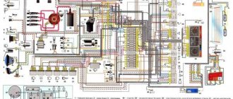
Fan relay diagram
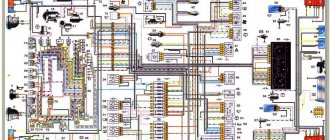
The figure shows the power supply circuit for the electric fans of the cooling system of the installation. Design elements are presented by numbers.
- 1/7 – left and right fan motors;
- 2 – additional power relay;
- 3 – fuse;
- 4 – power controller;
- 5 – auxiliary resistor;
- 6/8 – main relay for turning on the right and left electric motor, respectively;
- A/C – negative/positive battery terminal;
- B – to the main ignition relay.