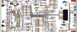
Wiring diagram for VAZ 2109
Many owners of the VAZ 2109 often need a complete electrical diagram and wiring diagram for the VAZ 2109 carburetor before their eyes. Here you can find a complete wiring diagram for the VAZ 2109 measuring 5000 by 2900 pixels, that is, it is huge.
Download diagram
Numerical designations on the diagram
| 1. Block headlight. | 2. Electric motors for headlight cleaners*. | 3. Lamp switch under the hood. |
| 4. Sound signal. | 5. Engine cooling fan electric motor. | 6. Fan motor activation sensor. |
| 7. Generator. | 8. Solenoid valve for turning on the headlight washers*. | 9. Rear window washer activation solenoid valve*. |
| 10. Windshield washer activation solenoid valve. | 11. Spark plug. | 12. Ignition distributor sensor. |
| 13. Ignition coil. | 14. Reversing light switch. | 15. Coolant temperature gauge sensor. |
| 16. Starter. | 17. Accumulator battery. | 18. Brake fluid level sensor. |
| 19. Switch. | 20. Top dead center sensor for cylinder 1. | 21. Diagnostic block. |
| 22. Carburetor solenoid valve control unit. | 23. Starter activation relay. | 24. Carburetor limit switch. |
| 25. Carburetor solenoid valve. | 26. Oil pressure warning light sensor. | 27. Window washer motor. |
| 28. Heater fan motor. | 29. Additional resistor for heater motor. | 30. Heater fan switch. |
| 31. Windshield wiper motor. | 32. Cigarette lighter. | 33. Heater lever illumination lamp. |
| 34. Plug socket for portable lamp. | 35. Engine compartment lamp. | 36. Glove box lighting lamp. |
| 37. Mounting block. | 38. Instrument lighting switch. | 39. Parking brake warning lamp switch. |
| 40. Brake light switch. | 41. Understeering's shifter. | 42. External lighting switch. |
| 43. Hazard switch. | 44. Rear fog light switch. | 45. Fog light circuit fuse. |
| 46. Heated rear window switch. | 47. Side direction indicators. | 48. Ceiling lamp. |
| 49. Connector for connecting to an individual lighting lamp. | 50. Light switches on the door pillars. | 51. Ignition relay. |
| 52. Ignition switch. | 53. Instrument cluster. | 54. Carburetor choke warning lamp switch. |
| 55. Rear lights. | 56. Level indicator and fuel reserve sensor. | 57. Rear window heating element. |
| 58. Rear window wiper motor. | 59. License plate lights. |
Numbering order of plugs in blocks:
- A – ignition switch;
- B – windshield wiper electric motor.
* – Installed on parts of manufactured vehicles.
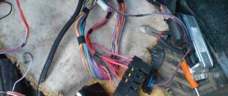
Installing a new injector
If you decide to install a new injector, then you will have to partially change the wiring. To avoid mistakes when connecting a new electronic device, it is advisable to take photographs of the wires that supply power to the old injector. Next, from the passenger compartment we drag the bundle of corresponding conductors along with their connectors into the space under the hood. On one side of the terminal block the ends of the harness are connected, on the other side - the corresponding sensors.
If your car has a high dashboard, then it is necessary to partially disassemble it and remove these devices. In a car service center, the work of replacing the device costs about the same as the injector itself. So it will be much more profitable to change it yourself. By doing this, you will not only save money, but also have a good understanding of the basic principles of the electronic system.
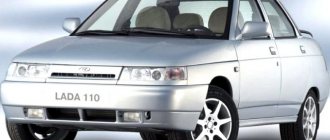
Previously, a carburetor was installed on Ladas. For new developments in the domestic automobile industry, an injector began to be used. Due to this, another wiring harness was added connecting the controller to the fuel frame.
In the “ninety-nine” the carburetor is quite well designed and works great on almost any gasoline. It has two chambers in which gasoline is first distributed and then supplied to the piston block. In one chamber, the carburetor switches the engine from idle speed to its further throttling mode. In another chamber, the desired consistency of the combustible mixture is prepared by mixing gasoline with air. At high engine speeds, the combustible mixture is enriched using an econostat.
The carburetor of the “nine” has an offset damper. When the air flow opens it, pulling back the spring, uniform mixing of the combustible mixture occurs. When starting a cold engine, the starting device is engaged in fuel enrichment.
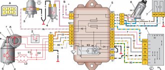
At idle speed, the carburetor is controlled by an economizer, which includes a control unit, a switch and a solenoid valve.
Ignition circuit for VAZ 2109 carburetor
Is the ignition starting to fail? Then I recommend taking this diagram and, armed with a multimeter, ringing all the elements of the circuit.
Download diagram
Numerical designations on the ignition diagram
| 1. Accumulator battery. | 2. Generator. | 3. Ignition coil. |
| 4. Mounting block. | 5. Switch. | 6. Egnition lock. |
| 7. Distributor. | 8. Spark plug. |
Controller diagnostics
Electrical diagram of VAZ 21214 Niva injector and photo
To diagnose the controller, you will need a graduated thermometer that can operate at the boiling point of water. The diagnostic procedure is carried out as follows:
- Often the sensor facing the inside of the radiator should be placed in water.
- Next, the tester probes are connected to the controller contacts, and they are adjusted to ensure there is no resistance.
- When the liquid begins to heat up, the resistance disappears at approximately 87-92 degrees. If so, then the controller is healthy and will work as expected.
The VAZ 2107 fan switch sensor is responsible for the timely switching on of the radiator fan, which prevents the possibility of engine overheating when driving at low speed and in other conditions when natural airflow is not enough for effective cooling. Otherwise, the antifreeze may boil and even cause engine damage.
VAZ 2109 fuse diagram
Has the fuse blown again? Because you loaded your VAZ 2109 with a powerful light or installed a sub for which the wiring and fuse box were not designed? Then this fuse diagram will come in handy!
| № | Ampere | Purpose |
| 1 | 8 | Right fog lamp |
| 2 | 8 | Left fog lamp |
| 3 | 8 | Headlight cleaners (at the moment of switching on) Headlight cleaner switching relay (contacts) Headlight washer switching valve |
| 4 | 16 | Headlight wiper motor Headlight wiper relay (winding) Heater motor Window washer motor Rear window wiper motor Rear window washer timing relay Windshield and rear window washer activation valve Cooling system electric fan relay relay coil Coil of the rear window heating relay coil Rear window heating control lamp Wardrobe lighting lamp box |
| 5 | 8 | Turn indicators in turn signal mode and the corresponding indicator lamp Rear lights (reversing lamps) Indicator lamp for fuel reserve, oil pressure, parking brake, brake fluid level, carburetor choke Voltmeter and indicator lamp for charging the battery Gearmotor and windshield wiper switch relay Generator excitation winding (at start-up) “STOP” indicator lamp Coolant temperature and fuel level indicators |
| 6 | 8 | Rear lights (brake lights) Body interior light Power windows and power window relay |
| 7 | 8 | License plate lights Engine compartment lamp Indicator lamp for turning on side lighting Instrument lighting lamp and cigarette lighter lamp Heater lever illumination panel |
| 8 | 16 | Engine cooling fan electric motor and its activation relay (contacts) Sound signal and its activation relay |
| 9 | 8 | Left headlight (side light) Left rear light (side light) |
| 10 | 8 | Right headlight (side light) Right rear light (side light) |
| 11 | 8 | Direction indicators and hazard warning relay (in hazard mode) Hazard warning lamp |
| 12 | 16 | Heated rear window element and heating relay Cigarette lighter Socket for portable lamp |
| 13 | 8 | Right headlight (high beam) |
| 14 | 8 | Left headlight (high beam) High beam indicator lamp |
| 15 | 8 | Left headlight (low beam) |
| 16 | 8 | Right headlight (low beam) |
| Relay | ||
| K1 | Rear window washer time relay (451.3747 / 2108-3747110, 2108-3747110-06) | |
| K2 | Relay-breaker for direction indicators and hazard warning lights (493.3747 / 2108-3747010-02) | |
| K3 | Windshield wiper relay breaker (522.3747 / 2108-3747710) | |
| K4 | Contact jumpers in place of the lamp integrity monitoring relay. Lamp integrity monitoring relay (4402.3747 / 21083-3747410, 21083-3747410-06) | |
| K5 | Headlight high beam relay (113.3747 / 2105-3747210-10, 2105-3747210-12) | |
| K6 | Headlight cleaner relay (112.3747 / 2105-3747210, 2105-3747210-02) | |
| K7 | Power window relay (13.3747 / 2105-3747210-10, 2105-3747210-12) | |
| K8 | Relay for turning on sound signals (13.3747 / 2105-3747210-10, 2105-3747210-12) | |
| K9 | Relay for turning on the electric cooling fan (13.3747 / 2105-3747210-10, 2105-3747210-12) | |
| K10 | Relay for turning on the heated rear window (13.3747 / 2105-3747210-10, 2105-3747210-12) | |
| K11 | Relay for low beam headlights (13.3747 / 2105-3747210-10, 2105-3747210-12) | |
Lighting and sound devices
- Instead of activating brake lights in the rear lights, when you press the brake pedal, real “color music” begins;
- The sound signal is unstable;
- The radio or radio is also unstable.
Damaged parts must be replaced
Note! Here the instructions will be similar - immediately find the burnt contact (in the photo) and repair it. And if impossible, replace with new parts. You can read about how to fix a similar problem with contacts on a GAZelle in our other article.
Wiring diagram for power windows on a VAZ 2109
Tired of lifting windows with ordinary “oars”? Then install electric windows using the wiring diagram for electric windows on a VAZ 2109.
Download diagram
Numerical designations on the diagram
| 1. Mounting block. | 2. Ignition relay. | 3. Egnition lock. |
| 4. Right door electric window motor. | 5. Left door electric window motor. | 6. Right door power window switch. |
| 7. Left door power window switch. | K7. Power window power relay. | A. To terminal “30” of the generator. |
| B. To the wiring harness block connected to the heater lever illumination display. | ||
Maintenance
The operation of domestic cars has national characteristics:
- owners prefer to maintain and repair their cars with their own hands;
- This requires a detailed diagram of the main systems.
In the video presented in the article you can see which components and electrical circuits require constant monitoring by the owners.
Conclusions: cars of the VAZ 21093 family still serve today, delighting owners with their reliability. And any failures can be easily corrected yourself, having a detailed electrical wiring diagram at hand.
VAZ 2109 generator circuit
If you lose charge, this is most often due to a failure of the generator, and most often it is the generator brushes, but it happens that there are winding breaks and a short circuit in the circuit or an open circuit. In this case, I recommend that you familiarize yourself with this generator circuit for the VAZ 2109.
Download diagram
Numerical designations on the diagram
| 1. Generator. | 2. Negative valve. | 3. Additional diode. |
| 4. Positive valve. | 5. Battery discharge warning lamp. | 6. Instrument cluster. |
| 7. Voltmeter. | 8. Mounting block. | 9. Additional resistors of 100 Ohm, 2 W. |
| 10. Ignition relay. | 11. Ignition switch. | 12. Accumulator battery. |
| 13. Capacitor. | 14. Rotor winding. | 15. Voltage regulator. |
The weak link in the electrical equipment of Lada
In a VAZ car, such repairs or replacement of the device are carried out as follows. All terminals are unscrewed and wires are removed. The nut that regulates the tension of the generator belt is loosened. Then the device moves away and the belt is removed. After unscrewing the bracket and the adjusting bar, the faulty generator is removed. A new device is installed in its place. Installation of a new generator is carried out in reverse order.
To avoid problems with recharging the battery in the future, this procedure should be repeated after the next ten thousand kilometers.
Turn signal diagram for VAZ 2109
Don't they blink? Then go through the circuit with a multimeter and find out the cause of the turn signal malfunction.
Download diagram
Numerical designations on the turn signal diagram
| 1. Block headlight. | 2. Turn signal repeaters. | 3. Fuse mounting block. |
| 4. Ignition relay. | 5. Egnition lock. | 6. Indicator lamps on the instrument cluster. |
| 7. Rear lights. | 8. Hazard switch. | 9. Turn signal switch. |
| K2. Relay for direction indicators and hazard warning lights. | ||
A few words about the procedure for working with wiring
Engine cooling system VAZ 2115 injector diagram
At the end of today’s article, we’ll look at exactly how you should proceed if you want to change the wiring. As an example, let's take standard models of the VAZ brand - 2110, 2109 and the like. So, to competently work with car data electronics you will need:
- First, prepare for repair procedures. The implementation of this goal lies through:
- Purchasing the required wiring and devices;
- Search for the necessary connection diagrams;
- Selection of auxiliary tools: harnesses, fasteners, gloves for work, etc.
- After this, acting according to the diagrams of the currently installed electronics, we completely remove it. Naturally, before this you need to turn off the engine, disconnect the battery and put on gloves;
- Then the actual replacement of the VAZ wiring begins. Here you also need to act taking into account the connection diagrams. First of all, we connect the injector wiring according to the principle “from the oldest element to the youngest”. Next, we connect the main wiring outputs (ECU contacts) with the current source, and at the end we connect other electronics.
Of course, the noted procedure is only generalized, but, in general, compliance with it and compliance with the described rules for working with car wiring is the key to the success of such repairs. We hope that today's material was useful to you and provided answers to your questions. Good luck in maintaining and operating your car!