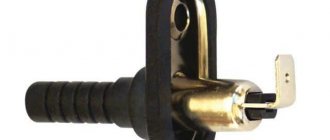
During the operation of any car, the need arises to replace parts and assemblies. If you intend to install a new injector on a VAZ 21099, then in recent years the automaker has been producing a unit with an M73 21114-1411020-12 Itelma controller, for which you will also have to replace the wiring.
Electrical wiring on a VAZ 21099 for a new controller
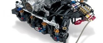
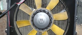
Working in the engine compartment
The injection system parts themselves are identical in overall dimensions. The difficulty is:
- The need to remove standard wiring;
- Disabling sensors that were covered by wiring;
- Removing the old injector and installing a new one;
- Connection to the electronic unit and sensors.
The electrical wiring of the VAZ 21099 to the injector has been dismantled
Advice: if you do not have experience in replacing wiring, then to make the work easier, use a camera - a photo or even a video that you took before dismantling in the engine compartment will help to avoid errors when connecting.
After the new parts are installed on the power unit, we begin installing new wiring. The process itself will proceed according to the following algorithm:
- From the interior side, we drag the wiring harness with connectors into the engine compartment (the desired edge can be easily determined by the connectors, comparing them with the old wiring);
- We pass it through, distributing the bundles among the connection points (the longest ones are to the side lights and headlights with washers);
- We connect the terminal blocks to the sensors and connectors.
See also the wiring diagram for the VAZ 21074 injector.
The weak link in the electrical equipment of Lada
In terms of reliability, the electrical equipment circuit of the Lada 21099 is not inferior to some foreign cars. The low dashboard was inherited from the G8, so all instruments are connected identically. The weak link of this VAZ model is the flexible board for connecting the rear lights. The conductive paths are quickly erased, causing contact with the lamps to be disrupted. Since no repairs are provided here, quite often the entire board has to be replaced.
If the Lada 21099 does not start, you should first measure the voltage at the battery terminals. When the battery is completely discharged, it is necessary to check the functionality of the generator. If it fails, it will have to be replaced or repaired.
In a VAZ car, such repairs or replacement of the device are carried out as follows. All terminals are unscrewed and wires are removed. The nut that regulates the tension of the generator belt is loosened. Then the device moves away and the belt is removed. After unscrewing the bracket and the adjusting bar, the faulty generator is removed. A new device is installed in its place. Installation of a new generator is carried out in reverse order.
| Stages of work | What to pay attention to |
| In order to charge the battery efficiently, you should not forget about the belt tension. | If the belt is loosely tensioned, it will definitely slip, which is why the battery will not receive the required charge. With normal tension, the belt should not sag by more than 10 millimeters. |
| Make sure you have the tools to make this repair. | It is advisable to have an open-end wrench 17 by 19, as well as a pry bar. |
| It's done like this. First, the fixing nuts are loosened. A pry bar is inserted between the generator unit and the engine block. Then, using a pry bar, the generator is pulled out and the nuts are tightened. | After this, the belt tension is checked again. If it no longer sags, then we can assume that the repair was successful. |
To avoid problems with recharging the battery in the future, this procedure should be repeated after the next ten thousand kilometers.
Work in the salon
This is the most difficult stage of DIY work, because:
- The instrument panel is difficult to install;
- Requires partial disassembly and removal of devices;
- Requires replacement of some terminals.
The VAZ 21099 wiring to the instrument panel injector is connected to the new one after re-soldering the connectors
Precautionary measures
When working with electrical equipment, the following precautions should be observed:
- Familiarize yourself with the requirements contained in the standard instructions;
- Disconnect the battery;
- Work with terminals and contacts using rubber gloves to avoid unnecessary contamination.
See also the VAZ 2107 wiring diagram.
Replacing the pad
The complexity of the upcoming work lies in the fact that on older models the instrument panel wiring harness connectors are made with 9 contacts. And in order not to change it, you can use the old one.
And for this you will need:
- wiring diagram for VAZ 21099 injector for clarity;
- old block, cut from the removed wiring;
- availability of free time and desire.
9-pin header to be replaced
Advice: the price for such work in a car service is equal to the cost of the injector itself, so the incentive for independent work is more than significant.
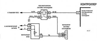
Diagram of devices connected to the block
Step-by-step instructions for replacing the pad are as follows:
- the wire transmitting readings from the speed sensor must be connected to pin 9 of the block (indicated as SP in the diagram);
- The Check Engine signal is sent to pin 8 of the block (BP);
- The fuel consumption sensor transmits information to the trip computer (MC);
- the diagnostic block is connected to the GB and interacts with the BC;
- the electronic tachometer receives information from the ECU and is output to pin 2 of the block (on the gearbox diagram);
- The RF connector provides 12V power and also powers the starter relay. The operation of the Check Engine is also tied to it;
- the starter is started through the ignition switch, and the inverter connector activates an additional relay when the key is turned to the “Starter” position;
- The 12 V ignition switch power is redistributed to the instrument panel via the GPU connector. Also supplies power to the ECU and the fuel pump to start the engine;
- Connector P is responsible for information about the level of gasoline in the car tank.
The process of connecting the block on the gas tank
For reference: The electrical harness of the fuel pump (in the diagram - EMS) is separate from the cabin wiring. Contact from the fuel pump occurs directly to the SUD, and only then to the cabin wiring.
Displaying information on the instrument panel
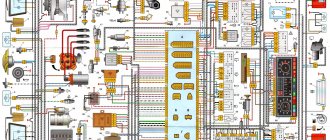
In the technical description, the electrical circuit diagram of model 21099 indicates the connection of the ignition switch, generator, and on-board control system devices. In order to be able to repair a specific unit, the Lada 21099 diagram shows the connection of control lights built into the dashboard.
The lamps highlight the following information:
- Availability of brake fluid:
- operation of the alarm system;
- oil pressure;
- turning on high or low beam;
- parking brake;
- heated rear window;
- turns;
- fuel level;
- coolant temperature.
Also, the electrical circuit diagram of a VAZ car indicates the connection of an electronic tachometer. If you need to repair any electrical equipment, it is advisable to contact a car service specialist. Some owners of car 21099 install a piece of large-section wire in place of the blown fuse. This can cause all the wiring to catch fire while driving.
Without extensive experience and special knowledge, it is undesirable to independently repair the electrical wiring of a VAZ car.
After the “ninety-nine” entered the automobile market, many car enthusiasts did not really know how the injector responsible for the fuel injection system worked. Until 2004, the car had a carburetor. Now, while operating the machine, it is advisable to have an understanding of the operating features of the electronic system and its interaction with the power unit. The phases in which the injector supplies fuel are controlled using a controller.
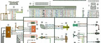
Ignition circuit for VAZ 2109 carburetor
Is the ignition starting to fail? Then I recommend taking this diagram and, armed with a multimeter, ringing all the elements of the circuit.
Download diagram
Numerical designations on the ignition diagram
| 1. Accumulator battery. | 2. Generator. | 3. Ignition coil. |
| 4. Mounting block. | 5. Switch. | 6. Egnition lock. |
| 7. Distributor. | 8. Spark plug. |
How the signal is transmitted
Thanks to the different color markings of the wires, the driver can understand the electrical circuit and find exactly the wire that is needed to solve a particular problem. To ensure high-quality and uninterrupted transmission of the electrical signal, you must do the following:
- use wires with a suitable cross-section;
- monitor the contact resistance, which should be minimal for removable connections;
- monitor the integrity of the insulation of electrical conductors.
The operation of the VAZ-2109 injector engine, as well as its dynamic characteristics, is primarily affected by the condition of the electrical wiring, therefore, it must be constantly and carefully monitored.
Having familiarized yourself with the intelligent color wiring diagram, even without the presence of a special measuring device, you can quite easily independently find a fault in the electrical wiring, even the most insignificant one. Eg:
- find out why the ignition stopped working;
- determine why the starter does not turn on;
- due to which the generator lacks voltage;
- which led to a breakdown of the heating system.
If the cross-section of the conductor decreases, this will lead to a deterioration in the transmitted electrical signal, which will subsequently increase the temperature. Sometimes an external examination will not help to identify a violation of the integrity of the veins, and only a deep examination will help to identify such destruction. The integrity of the wiring is compromised due to oxidation of the contacts, and since such a process is inevitable when operating machines, this means that they need to be cleaned periodically.
If the electrical signal is supplied in a distorted form, then the malfunction will be felt throughout the entire VAZ-2109 injector system.
Types of electrical circuits
We disconnect the steering wheel, steering column trim and steering column switches.
Broken wiring Injection motor As for injection internal combustion engines with injectors, malfunctions in them, as practice shows, are usually associated with failure of the sensors or the electrics themselves. Therefore, any electronics check begins with checking this unit. And special sensors that the engine is equipped with are responsible for this: DPKV crankshaft position sensor.
The heater should be assembled in the reverse order of disassembly.
Adjust the center shutter. New clamps should be used.
See also: Power supply design
See also related news
Be sure to adjust the travel of the dampers. VAZ diagram old versions VAZ diagram new versions There is no brake pad wear sensor. Previously, the handbrake lamp blinked when the lever was raised, and lit up constantly when the sensors on the brake pads were activated. The VAZ injector, electrical diagram, includes many sensors and fuel pump regulators, their diagram is posted on the websites of car enthusiasts.
If the sensor reacts to metal, it means it is working. Adjust the center shutter. All these control and monitoring lines are assembled into one block and at the output they are connected to the nodes using connectors on the control circuits and signal sensors from the mechanisms.
What kind of problems does an electrical circuit help to solve?
Connection diagram for starter VAZ, VAZ, VAZ A - pull-in winding; B - holding winding; 1 - starter enable relay; 2 — mounting block; 3 — ignition switch; 4 - generator; 5 - battery; 6 — starter Fig. You can disconnect the alarm wiring and the backlight lamp. Modification of a car with a VAZ carburetor engine, 1.5 liters and 73.4 horsepower.
This circuit is used to identify a malfunction in the automotive mounting block. Years of production: — in Russia, — — in Ukraine. Limit switch for reverse gear lights. what is required to install the injector on a vaz
Turn signal diagram for VAZ 2109
Don't they blink? Then go through the circuit with a multimeter and find out the cause of the turn signal malfunction.
Download diagram
Numerical designations on the turn signal diagram
| 1. Block headlight. | 2. Turn signal repeaters. | 3. Fuse mounting block. |
| 4. Ignition relay. | 5. Egnition lock. | 6. Indicator lamps on the instrument cluster. |
| 7. Rear lights. | 8. Hazard switch. | 9. Turn signal switch. |
| K2. Relay for direction indicators and hazard warning lights. | ||
Practical advice
The operation of an injection power unit, and in particular the maintenance of its electronic components, is fundamentally different from carburetor engine systems.
Owners of converted cars must learn a few basic rules:
- Before dismantling the injection control system components, be sure to disconnect the negative cable from the battery terminal;
Working with car wiring requires care and precision.
- Do not start the engine if the terminals of the wires on the battery have poor contact. Be sure to check how tightly they are tightened;
- Do not disconnect the battery while the vehicle engine is running. This is guaranteed to lead to failure of the ECU;
- Monitor the ECU temperature. It is not allowed to overheat (65°C when the car is running and above 80°C, for example when drying in a paint booth). If such a process is unavoidable, remove the ECU from the vehicle for the duration of the work;
- It is also necessary to remove the ECU or disconnect it from the vehicle’s on-board system when carrying out welding work on body parts.