Rice. 1.4. On-board control system
The on-board control system block is shown in Figure 1.4.
1 – indicator of insufficient oil level in the engine crankcase. Lights up orange if the oil level in the engine crankcase has dropped below the “MIN” mark of the indicator. Before adding oil, check whether there is any oil leakage due to loss of tightness of the lubrication system.
2 – indicator of insufficient washer fluid level in the windshield washer reservoir. Lights up orange if there is less than 1 liter of washer fluid left in the reservoir.
3 – indicator of insufficient coolant level in the expansion tank. Lights up orange when the coolant level on a cold engine drops below the permissible limit. Before adding fluid, check the cooling system for leaks.
4 – door open indicator. Lights up red when the car door is not closed.
5 – fault indicator for brake light lamps or side lights. Lights up red if there is a malfunction of the brake light lamp when you press the brake pedal or any side light lamp when they are turned on.
6 – front brake pad wear indicator. Lights up orange when you press the brake pedal and stays on until the ignition is turned off if the thickness of the front brake pads has decreased to 1.5 mm.
7 – seat belt unfastened indicator. Lights up red if the driver's seat belts are not fastened.
Functional modes of the block:
– pre-departure control of signaling devices;
The unit is in the "Off" mode until the key is inserted into the ignition switch. In position 0 (“Off”) of the key in the ignition switch, the unit goes into “Standby Mode”. If the driver’s door is opened, a “Forgotten key in the ignition switch” malfunction will occur and the unit’s audible alarm will emit an intermittent signal for 5–7 seconds. The signal can be interrupted either by closing the door, or by removing the key, or by turning the key in the ignition switch to position I (“Ignition”). In position I of the key in the ignition switch, the unit switches to the “Pre-departure monitoring of signaling devices” mode, in which, to check their serviceability, all light and sound signaling devices are turned on for 3–5 s, and then after a pause of 1 s, the unit switches to the “Parameter Monitoring” mode. and if there is a malfunction, produces an alarm according to the following algorithm:
– the indicator light for the parameter that is outside the normal range begins to blink for 5–7 s, after which it switches to a constant glow mode until the malfunction is eliminated or the key in the ignition switch is returned to position 0 (“Off”);
– simultaneously with the light indicator, the sound indicator turns on for 3 s;
Checking the indication
There are 5 indication modes:
- off – when the key is not in the ignition switch;
- standby mode - the BSK VAZ 2114 goes into it when the key is inserted into the ignition, but remains in the “Off” position; if you open the door, an error about a forgotten key will be displayed. You must close the door or remove the key to stop the horn;
- test - turns on when the ignition key is turned to the “Ignition” position. A sound signal and the turning on of all the system lights indicate that the device is working properly. Afterwards, all systems are tested, while the sensors are turned off;
- preliminary test - after testing is completed, the VAZ 2114 display unit, if there are malfunctions, the diode responsible for a certain parameter begins to blink for 8 seconds, after which it lights up evenly until the key is returned to the “Off” position. The blinking of the indicator is accompanied by a rhythmic sound signal;
- test with the engine running - this mode for BSK 2114 is the final stage of control. Monitoring of sensor parameters goes into sleep mode. It only carries out periodic additional monitoring of the vehicle’s performance. All malfunctions that occur in this mode are remembered until the end of the trip and the lights glow steadily.
In case of traffic problems, notification is carried out according to the preliminary test algorithm from 8c. blinking
System problems
Summarizing the experience of drivers, the most common problems occur in the ignition switch. The limit switch in it should receive 12 volts. Sometimes it is the installers who confuse the diagram, after which the BSK not only does not see the door, but also does not work at all. To check functionality, you must disable the limit switch. If the BSK turns on, but does not see the door, then the problem is here.
For other cases, you will have to resort to checking the systems one by one according to the pinout diagram:
- Replacement and diagnostics of the coolant temperature sensor (DTOZH) VAZ 2114
- Checking and replacing the mass air flow sensor (MAF) on a VAZ 2114
- Outside air temperature sensor for VAZ 2114: purpose, causes of failure and ways to eliminate them
good afternoon, AM 2114 8 class. I encountered a problem, after starting the car the bsk started to light up just dimly (all diodes). Can anyone tell me what the problem is? Also, with each shutdown and start-up, the instantaneous mileage and clock began to reset to 00.
Afterword
Car owners whose cars keep melting fuses should be sure to check all installed wiring at the first opportunity.
Very often this problem is evidence of serious damage in one or more circuits. To do this you will need detailed:
- electrical circuit;
- pinout;
- tester.
If you lack the necessary knowledge, it is better not to undertake repairs yourself, but to entrust this task to professionals. The fee for their services, of course, can be quite high, but eliminating the consequences of unqualified intervention will cost much more.
Scheme and operating principle of BSK VAZ-2108 (2109)
You can often find a diagram for connecting a BSK on the Internet, but it is very difficult to find a diagram for the BSK itself. In one of the methodological instructions there was also a diagram and a description of the work. It looks like this is only a fragment of the diagram, but it may be useful. So, the text below is a quote from “Electronic systems of mobile machines”, authors Dorovskikh D.V., Kurochkin I.M.
The VD2 “fasten seat belts” indicator lights up when the seat belt limit switch K1 is connected to the car body. Resistor R1 serves as a current driver through the LED VD2, and diodes VD1, VD3 protect the indicator from interference.
The VD6 brake lining wear indicator works as follows. At the first braking with worn linings, the lining wear sensor (closing type) connects contact K2 BSK to the car body. The normally open switch on transistor VT1 closes; at output 1 of trigger DD1.1, a high voltage level is established, which opens transistor VT2 through diode VD5 and resistor R5. At the same time, the VD6 LED starts to light. The warning light will turn off only when the ignition switch is turned off. The serviceability of the signaling device is monitored by the “Test” signal through the VD7 diode. The same signal through resistor R7 resets the trigger to its original state. Circuit R4, VD4 and C1 serves to limit the amplitude and filter noise of the signal coming from the brake lining wear sensor.
The VD11 indicator for faulty brake and side lamp lamps operates on a similar principle. If at least one of the lamps malfunctions, voltage from the vehicle's on-board network appears at the short-circuit contact of the BSK (from the output transistor of the lamp health monitoring relay). Using the chain R8, R9, VD9, this voltage is limited to 4.7 V. At the same time, the filter R8, C2 serves to protect the alarm from false alarms due to induced noise. Trigger DD1.2 is set to logical “1”. A high signal level from output 13 of DDI.2 through diode VD8 and resistor R10 opens transistor VT3. At the same time, the VD11 LED starts to light. The warning light turns off only when the ignition switch is turned off. Via the VD10 diode, the serviceability of the alarm is monitored using the “Test” signal. Simultaneously with the VD11 indicator switching on, the base of the VT4 transistor is connected to the car body through resistor R13, VD12 diode and VT3 transistor, which turns on the HL1 “STOP” warning lamp.
The VD15 emergency oil pressure indicator lights up when contact K4 of the pressure sensor is connected to the car body. Transistor VT5 is used to test the alarm using the “Test” signal. When the VD15 signaling device is turned on, an unlocking voltage bias is supplied to the base of transistor VT4 through the VD14 diode and resistor R13, and at the same time the HL1 “STOP” signaling lamp lights up. Diodes VD13, VD16 protect the alarm from false alarms due to interference.
The brake fluid level indicator, which is not shown in the diagram, works similarly.
The VD20 washer fluid level indicator works as follows. If the washer fluid level is below a certain level, then the level sensor connects the emitter of the VT6 transistor to the car body through contact K5. When the ignition switch is turned on, when the engine crankshaft speed is less than 750 rpm, a signal is present at the special BSK “Control” contact that opens transistor VT6 through resistor R17. At the same time, the VD20 LED lights up. Through transistor VT7, the alarm is checked using the “Test” signal. Thus, it is possible to control the level of washer fluid when the ignition switch is turned on after the end of the “Test” signal, i.e. carry out so-called “pre-departure” control of this parameter.
Oil and coolant level indicators, not shown in the diagram, work in a similar way.
The VD21 voltage monitoring device for on-board network voltage has a control circuit assembled on comparators DA1.1, DA1.2 and transistors VT8, VT9. A voltage proportional to the voltage of the vehicle's on-board network UBC is supplied from the voltage divider across resistors R16, R27 to the inverting input of the comparator DA1.1 and the non-inverting input of the comparator DA1.2. The ratio of the values of the precision resistors in the divider R19, R23, R29 is selected in such a way that the comparator DA1.1 switches from state “0” to state “1” at an on-board network voltage UBS of 15 V. At a voltage of UBS 15 V, the control signal of transistor VT8 is modulated at using transistor VT9 with a frequency of 2 Hz. In this case, the VD21 LED blinks at a frequency of 2 Hz. The VD19 zener diode and SZ capacitor protect the circuit from surge voltages that occur in the vehicle's on-board network.
Why do you need an on-board computer?
In previous articles we have already talked about what an on-board computer is, what it is needed for and what types they come in. But let me repeat myself so that you clearly understand all the advantages of having an on-board computer, and there are probably no disadvantages, except perhaps spending money on the purchase and that’s all.
Let's take, for example, the on-board computer STATE 115×24. With this model in your possession, you can:
- set the radiator fan start temperature; this function is very useful, for example, in winter, when you can control the temperature of the coolant, thereby monitoring the temperature of the heater radiator.
- The function of drying and warming up the spark plugs before starting the engine is very useful.
- The function of resetting settings and ECU adjustments is needed to switch to gasoline with a higher or lower octane number (from 92 to 95 and vice versa), and this function is also needed to reset settings after a long trip with increased load on the engine.
- The ability to read errors allows you to monitor the condition of the car and change non-working sensors and elements in a timely manner.
Main elements of the control panel
The most important place in the car is given to such instruments as the tachometer and speedometer; this also includes a fuel gauge and coolant temperature. And it’s worth examining these devices in more detail so that everything is clear in the future.
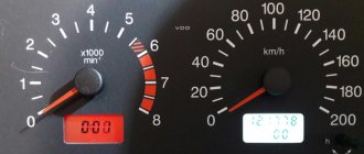
Tachometer
It is presented in the form of a device with an arrow; its signal comes to the on-board computer of the model. This device displays data on vehicle speed. In total, the tachometer has 5 scales, and every second scale has numbers here, the maximum number of revolutions is 80. In order to determine the speed, you need to multiply the number indicated on the tachometer by 100. Manufacturers on the device indicated the maximum number of revolutions, upon reaching which the car engine can go out of gear. building. Below it there is a small window where the time and air temperature outside are indicated.
Installation instructions for on-board computer
In this article we will look at the process of installing the Prestige on-board computer with diagnostic and error reading functions.
For work we will need:
- Screwdrivers,
- on-board computer,
- wire 1m long.
We remove the plug on the central dashboard and look for a 9-pin wiring block in it. This block must be present on all cars of our model. All that remains is to connect the block to the computer and that’s it, but we need to draw a K-line.
How to draw a K-line?
- We take our wire and install it in the second contact of our block.
- We throw the opposite end of the wire under the instrument panel down to the diagnostic block (for convenience, you can unscrew the right side panel).
- Having stretched the wire to the diagnostic block, we connect it to the “M” socket if you have a EURO-2 block or to the 7th socket if you have a EURO-3 block (it is very common that the diagnostic block for Euro-3 is installed upwards on the car feet, keep this in mind)
- Now we connect the on-board computer, insert it into its normal place and check it.
For a more complete and clear idea of the work, a diagram is presented.
What to do if there is no socket for the on-board computer under the instrument panel?
In this case, all that remains is to assemble a new block: buy a 9-pin block and run wires to it according to the following diagram:
- fuel consumption signal (green wire)
- ignition (orange wire)
- + 12 volts (red/white wire) red wire with white stripe
- mass (black)
- speed sensor (brown wire)
- 6k line (most often gray or black wire)
- mute (green/red wire) green wire with a red stripe
- backlight (white wire, or can be taken from the size button)
- fuel level sensor (pink)
Removal
1. Remove the instrument panel trim without disconnecting the wiring harness blocks from it (see “Instrument panel - removal and installation”).
2. Disconnect the wiring harness block from the display unit.
3. Using a Phillips screwdriver, unscrew the two self-tapping screws securing the block to the trim.
4. Remove the display unit.
Errors when connecting/operating the on-board computer
Error: “No connection with the controller” or “break in the K-line.”
This error indicates that the K-line is not connected or a contact break has occurred. Check the wire according to the diagram described above. Most likely the contact has come off the diagnostic block.
Error: Incorrect readings of the sea temperature sensor.
If your temperature outside is -40, then this indicates that the wire to the temperature sensor has broken, or there is no such sensor at all. If the temperature is, for example, -25, but it’s only -10 outside, then you need to replace the sensor with a working one.
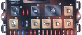
How to find out which fuse has blown
On each of the fuse blocks, or rather, on their covers, there is a diagram placed there by the manufacturer.
Using it, you can easily find out which circuit is responsible for which protection device. The cover can be removed by hand - no special tools are required. The non-working circuit element should be determined based on the nature of the problem. There are two ways to verify that the fuse has blown. If you have a multimeter, it will be safer to use it. To do this you need to do the following:
- turn on the ignition;
- set the tester to sound;
- Check each fuse in turn by touching their contacts.
The presence of a buzzer allows us to speak with confidence about the serviceability of the fuse.
If you don’t have a voltmeter, you can do without it, although it will take a little more time. You will have to pull out each surge protection element and carefully inspect it. There is a fusible insert inside it - its integrity indicates serviceability.
Repair manual for VAZ 2108, 2109, 2114, 2115
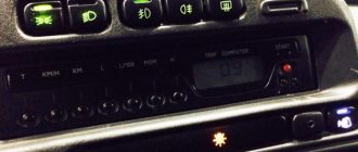
On vehicles, a variant version can be equipped with an instrument cluster with an on-board control system. It includes: a speedometer with daily and total distance meters, a coolant temperature indicator, a fuel level indicator, a tachometer, 13 warning lights and an on-board control system (OBS) unit.
Rice. 9.11. Electrical diagram of the connections of the instrument cluster with the on-board exhaust control system before 1996 (rear view): 1 – relay-breaker for the parking brake warning lamp; 2 – tachometer with voltage stabilizer; 3 – instrument cluster lighting lamp; 4 – temperature indicator; 5 – BSK control unit; 6 – fuel level indicator; 7 – resistor 50 Ohm, 5 W; 8 – control lamp “CHECK ENGINE” for the toxicity reduction system; 9 – control lamp for high beam headlights; 10 – side light indicator lamp; 11 – backup warning lamp; 12 – warning lamp for unfastened seat belts; 13 – control lamp for left direction indicators; 14 – resistor 470 Ohm, 0.25 W; 15 – electronic voltmeter; 16 – control lamp for right direction indicators; 17 – warning lamp for emergency oil pressure; 18 – fuel reserve warning lamp; 19 – control lamp for the carburetor air damper; 20 – indicator lamp “CHECK ENGINE” for the fuel injection system; 21 – parking brake warning lamp
There are two “CHECK ENGINE” indicator lamps in the instrument cluster. These lamps have different connections to the power source. Lamp 20 (see Fig. 9.11) has one terminal connected to the “+” power supply and is used in the fuel injection system. Lamp 8 has one terminal connected to ground and is used in emission reduction systems.
The BSK unit consists of an electronic control circuit and 8 LED indicators: oil level, washer fluid level, front brake lining wear, brake fluid level, serviceability of side light lamps, “STOP” and “TEST”. After turning on the ignition, all BSK indicators light up and go out after 5 seconds. If there is a malfunction in any of the circuits controlled by the BSC, the corresponding LED lights up.
The instrument cluster is attached to the front panel of the car with two nuts. The connections of the instrument cluster are made by printed wiring on a board made of foil getinax. The board is attached to the back of the case. The connection diagram of the instrument cluster is shown in Fig. 9.11. The terminals of the BSK block are connected to the plugs of the nine-terminal block, one terminal is connected to the “+” of the voltage stabilizer (located in the tachometer) and the second terminal is connected to the emergency oil pressure warning lamp. The addresses of the output plugs of the instrument cluster are given in the table. 9.3.
Wiring diagram for the light button VAZ 2114
Headlight switching diagram for VAZ-2113, 2114 and 2115
Scheme for switching on headlights and fog lights:
1 – headlights; 2 – mounting block; 3 – headlight switch; 4 – ignition switch; 5 – external lighting switch (fragment); 6 – fog lamps in the internal rear lights; 7 – fog light switch with control lamp; 8 – indicator lamp for high beam headlights in the instrument cluster; K8 – headlight high beam relay; K9 – relay for low beam headlights; A - the order of conditional numbering of plugs in the headlight block; B - to power supplies
Scheme for switching on the side lights of VAZ-2113, 2114 and 2115
External lighting switching diagram:
1 – side light lamps in headlights; 2 – engine compartment lamp; 3 – mounting block; 4 – engine compartment lamp switch; 5 – ignition switch; 6 – external lighting switch (fragment); 7 – indicator lamp for external lighting in the instrument cluster; 8 – side light and brake light lamps in the external rear lights; 9 – license plate lights; 10 – instrument lighting regulator; 11 – brake light switch; 12 – on-board control system unit; K4 – relay for monitoring the health of lamps (contact jumpers are shown inside the relay, which must be installed in the absence of a relay); A - to power supplies;
Scheme for switching on direction indicators and hazard warning lights for VAZ-2113, 2114 and 2115
Diagram for switching on direction indicators and hazard warning lights:
1 – direction indicator lamps in headlights; 2 – mounting block; 3 – ignition switch; 4 – alarm switch; 5 – side direction indicators; 6 – direction indicator lamps in the external rear lights; 7 – instrument cluster with turn signal indicator lamps; 8 – direction indicator switch; 2 – relay-interrupter for direction indicators and hazard warning lights; A - to power supplies
Date added: 07/14/2014
Author: Dmitriev Alexander
| © AutoService | Online store, Ekaterinburg The topic may be hackneyed, but when I started looking for information on how to do this, I mainly came across connecting the emergency lights and an article about connecting new buttons on the 2110. Let me start with the fact that recently I became the proud owner of 14 panels at a reasonable price) I threw it in pretty quickly, took half an hour to remove the old one, and about the same amount of time to push this one in (I had the wiring and lock left over from the carb version of my car), then the question arose with connecting the shield (which a Google search actually did a very good job of (plenty of information) and the method of scientific poking). Actually, the easiest part is over, hemorrhoids began with connecting the paired button for external lighting, as I already said, I did not find a clear and adequate answer on how to connect the 09 wiring with this button (H3, maybe I was looking crookedly, but oh well)))), using the method I managed to connect this device with a scientific poke and a tester. Below is the exterior lighting button block 2109, the pinout is indicated by wire colors for convenience))) Now the external lighting button is 2114, pinout is according to the wiring colors 2109))) Contacts A and E must be connected to each other in order for the low beam switch to light up) Let's move on to buttons 2109 for heated glass and fog lights, the pads for these buttons look the same where 1, 2 are contacts that can be closed to turn on the button, a, c are the button illumination (turned on with the dimensions) c, d is a separate wire for indicating the button’s activity (located separately from the main block). To begin with, here is the following diagram (in principle, it’s easy, we look for the button we need, look at the colors of the wires and screw it to the new button) Sorry for the signatures of the letters above, I signed for myself in the absence of a color printer))))) Well, the actual pinout of button 2114 (fog lights and heating are connected in the same way) a, c — button indication (lights up along with the dimensions), c, d — button activity indication (lights up when turned on). Well, connecting BSK 2114 to wiring 2109 Let's start with the pinout of the terminals. Terminal BSK 2109 (9 pin) And terminal BSK 2114 (13 pin) 1 Oil level 2 To the coolant sensor 3 To the washer fluid level sensor 4 Seat belts (if not, then screw them :-))) 5 To brake pad wear sensors 6 Driver's door switches 7 Passenger's door switches 8 Light switch circuit interior 9 The key is in the ignition switch (I have an old lock that doesn’t care about the inserted key, so I removed contact 9 from the orange wire of the red block (constant +) I know it’s not right, but what can you do) 10 Relay for monitoring the health of the lamps 11 Ground 12 ХЗ (not used) 13 To the ignition switch terminal to connect the BSK 2114, due to the fact that I have the wrong lock and terminal 9 is removed from the permanent + on the red block, the BSK starts working after you start the engine. I'm searching Google for a wiring diagram for BSK 2114 to 2109, but if you connect it according to that diagram, the starter continues to turn even after you throw the key. Here's the diagram This happens due to the fact that contacts 9 and 13 are closed to each other, which is apparently not correct, and actually I couldn’t connect using this diagram (((so it’s easier to print out the pinout of both blocks. Well, in the epilogue, the wires are short and need to be extended, here you should not be lazy and use a soldering iron and heat shrink, yes, it takes more time, but it will look good))) PS If anyone knows how to make the BSK work with the old lock immediately when you turn the key and not cause any problems, such as a constantly spinning starter, please write in the comments. Well, that’s basically it, today it’s been run in and tested) die Achtung: We supplement the article, the problem with the BSK is solved by switching the 13th block to the constant plus on the red block (orange wire) exactly the same wire that goes to pin 9 of the BSK) For greater convenience, the button for turning on the low headlights and the button for turning on the dimensions of the VAZ 2114 are made in pairs and are located on the European panel of the car. Both of them are equipped with additional built-in LEDs (two for backlighting, as well as an indication diode for side lights). As a rule, there are no problems with the operation of these buttons, but if necessary (for example, if they break), you should know how to replace them. Everything is done in the following order:
As you can see, the replacement can be done almost instantly, without applying any great effort or using a special tool. Another important point that should be highlighted is the pinout of the VAZ 2114 size button. It may be needed, for example, when replacing an old type button with a button for a Europanel. You can see it most clearly in the following diagrams: for old type buttons for new type buttons All letters indicated in the diagram correspond to the output contacts of the buttons and have similar markings to them, and the colors of the wires are indicated by letter abbreviations. Also, the pinout of the VAZ 2114 light switch button can help when troubleshooting problems in the operation of the buttons themselves, for example, if the backlight of one of them does not work. In this case, it should be taken into account that the contacts:
|
Reworking the low beam button
As already mentioned, the button for turning on the low beam and the button for the dimensions of the VAZ 2114 are combined and located in pairs. Their main drawback, which most car enthusiasts point out, is the absence of a power-on LED on the low-beam headlight button.
This problem is quite serious, since very often it becomes unclear whether the headlights are working or not (especially during daylight hours). You can solve this by upgrading the button yourself.
For this you will need:
- a button that will be redesigned;
- the second button is the same - donor;
- soldering iron or (better) soldering station.
The button modification should be carried out according to the diagram shown here. Resoldering the LED itself from one board to another is highly not recommended, since this requires a soldering station equipped with a hair dryer, a special flux and high skill in working with them.
First, we need to remove the main button from the car panel (how to do this has already been discussed above).
After it is removed and disconnected from the wires, perform the following operations:
- remove the keys by prying them off with a flat screwdriver;
- we disassemble the body of the buttons by pressing the latches with a screwdriver (the buttons themselves at this moment must be in the “on” position);
- we see that the sidebar button has two diodes (backlight and indication), and the low headlight button has only a backlight button;
- remove a pair of legs and a pair of contacts from the donor button;
- we rearrange them into the free spaces on the working button;
- remove the board from the donor button with two diodes and insert it into the working button instead of the board with one diode;
- solder the board to the legs that were added;
- make a hole in the button cover (this can be done with a sharp knife or simply punched with a flat screwdriver).
The junction of the newly installed legs and the new board must be well soldered. Otherwise, the button may quickly fail or not work correctly.
After all these operations have been completed, all that remains is to assemble everything in the reverse order and install the upgraded button in its place (during installation, it is important that all the mini-latches on the case fall into place).
Article rating:
How to connect BSK VAZ 2114 Link to main publication
Related publications
- How to treat a car with cannon fat
Replacement
Before replacing fuses, you must turn off the ignition and disconnect the battery. This will avoid electric shock.
How to remove a burnt one? The block itself must have special pliers for removing non-working protective equipment (they are supplied by the manufacturer along with the machine). It is better to insert a new one with their help as well. At the same time, it is important to ensure that it matches the previous value.
In a situation where there is no suitable fuse on the farm, a temporary jumper will help. Any copper or aluminum wire of sufficient cross-section will do for it. If necessary, it can be twisted several times.
If the fuse sparks when you turn on the power, then most likely there is a short circuit somewhere. You need to check all the contacts and wires coming from it. Sometimes it is necessary to remove the fuse box. To do this, you must first disconnect the negative terminal from the battery. Next, connectors with wires are disconnected in the cabin - first remove the top one. The block itself is held in place by nuts, which will need to be unscrewed with a 10 mm socket wrench. Then all that remains is to remove the bottom four pads and pull out the entire assembly. There is no need to be afraid of mixing them up during assembly, as they simply will not fit into the “non-native” socket.