DIY tuning
Do the panel tuning yourself, spending a minimum amount of money. The first option is to replace the arrows and stickers on the instruments. Sets of stickers and arrows are sold freely, you can use them, or you can develop individual designer stickers - this will of course be more expensive, but for that you will have a unique tuning of the dashboard of your car.
When performing this work, you need to remember two important points:
We must remember that the hands and pins on which they are placed are quite fragile parts, so they must be removed and installed with extreme caution. Before you start sticking on new dials, you need to:
- Mark the boundaries of the arrow on the scale at the zero position to prevent errors in the readings;
- Thoroughly degrease the surface of the instrument panel so that they do not come off during operation;
Typical owner
The average portrait of the owners of this Zhiguli model is as follows:
- middle age and above;
- they always know how much money they have in their wallet;
- practical and unpretentious;
- know how to save money.
For this type of people, it is preferable to update the interior while carrying out repair work related to the body. This will eliminate the need to disassemble the car interior - welding and painting work require this a priori. Not spending “extra” money is one of the desires of VAZ-2107 owners.
Do-it-yourself interior tuning will also allow you to save a certain amount. But provided that the owner knows how to work with his hands. That is, his hands grow from the right place. Otherwise, you will have to pay for this work separately. At the same time, no one will do a better job of tuning a car’s interior than its owner.
Tuning the instrument panel of VAZ 2107
Perhaps, everyone has a moment when the instrument panel in their VAZ car begins to seem dull and inconspicuous. In order to “revive” it, no expensive changes will be required, just make the backlight brighter and install a decorative sticker, which can be found in almost any car store, and replace the inserts on the dials. So, armed with a screwdriver and a soldering iron, we begin tuning the instrument panel of the VAZ 2107.
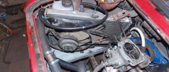
Removing the VAZ instrument panel.
The first step is to remove the sliders that control the operation of the heater (stove) using a flat-head screwdriver. Then, to the right of the emergency light button, unscrew and remove the nut and washer that secure the speedometer reset button. To the right of the removed sliders there is a small round plug that needs to be removed and the screw located behind it unscrewed. Then you need to carefully remove the instrument panel and release the speedometer cable by unscrewing the nut that tightens it. We disconnect all the wires, and the freed instrument panel remains in our hands.
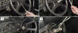
The next step is removing the arrows
This must be done extremely carefully so as not to bend either the arrow or the pin on which it sits. It is quite possible that you will have to apply force, but carefully, pulling the arrow in a direction parallel to the pin
Tuning the instrument panel.
Before all work, align the speedometer needle with the limiter, and make a mark on the back side so that you know in which position the needle “lies.” This will greatly simplify the installation of the speedometer and eliminate unnecessary work.
First of all, we remove the old VAZ 2107 shields (this is done quite simply) and install new ones in their place. Then carefully install the arrows, again, so as not to bend the pins
In this case, it is important to align the marks on the back side of the speedometer and, with the marks aligned, set the arrow in the “lying” position. We also carefully apply the sticker you like, having previously degreased the surface.
In this case, it is especially important to ensure that it lies flat and without distortions.
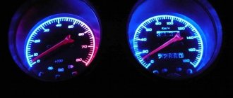
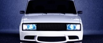
Installation of LED lighting.
There are two options for installing LED backlighting on a VAZ - directly behind the scale numbers, or as a general backlight for the entire instrument panel. Naturally, all this remains at your discretion, the main thing to consider is that in the first case the backlight will be quite bright and you will have to spend quite a lot of time soldering and gluing the LEDs.
The LEDs should be designed for an operating voltage of 12 Volts, and it is best to increase their contacts by 2-3 cm. For the first option, we remove all the standard light bulbs and solder LEDs in their place. After this, connect the power (it is best to dim the light and adjust the position and direction of the LEDs).
For the second option, if you want to illuminate the entire panel, you can install either four LEDs located in twos at the top and bottom of the instrument panel (choose the distance yourself, it depends on which part of the instrument panel you want to illuminate more), or six - three up and down. In this case, you will need to solder additional wires to connect the LEDs to power and drill out the mounting points. One option is to glue the LEDs with glue if they do not coincide in location with the power points. In this case, it is recommended to use only good glue, and be sure to degrease the installation sites.
In addition, with this arrangement of LEDs, there is a little trick to increase the strength of the backlight. Along the inner perimeter, you can cover the side surface of the instrument panel with foil - it will reflect light from the walls inward, enhancing the backlight. To decide how much you need it, it is better to assemble the panel, connect the power and think carefully about whether the backlight of such power will suit you.
Assembling the VAZ 2107 dashboard is done in the reverse order, there is nothing complicated about it. The main thing is that you achieved the desired result!
Torpedo 2107. connecting devices
- Please log in to reply.
#1 Antif
- Top
- Complaint
#2 Antif
- Top
- Complaint
#3 Valek-Yalta
- Top
- Complaint
#4 Antif
- Top
- Complaint
#5 Valek-Yalta
- Top
- Complaint
#6 Antif
I’ve been checking it for 4 days now, I did everything according to the diagrams, it feels like on a seven torpedo you need to turn on the lamp to light it, and not a plus like on a penny one. Although it seems like nonsense. I'll check again tomorrow. Well, your photos will be very relevant. And another question: Where to connect this air duct (2107-8104010). A sealant in the central air blowers and on the reverse side?
- Top
- Complaint
#7 Valek-Yalta
A sealant in the central air blowers and on the reverse side?
- Top
- Complaint
#8 Antif
well, a rubber seal. I’ll ask this: where the central air ducts are connected, it’s not written anywhere on the boxes:
The one at number 19, where should I connect it to the stove?
- Top
- Complaint
#9 Valek-Yalta
- Top
- Complaint
#10 Antif
- Top
- Complaint
#11 The Forester
And I'm guessing. Well, in seven of them they are somehow connected to the stove. I don’t get what the body has to do with it.
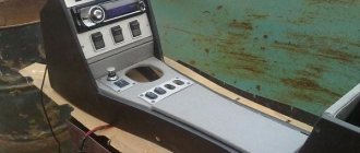
The deflectors in the middle of the panel are an air intake from the outside, and not from the stove. If you even pay attention to the deflectors themselves, they have “wheels” on the side in order to regulate not only the direction, but also the air flow (including blocking it completely). And they also have a hole in the body for the air supply of the stove, to which the central deflectors are actually connected, and which the 2101 does not have:
I think the photographs show everything quite clearly
This is the perfect place for a radio or additional buttons/switches.