Print this article Font size 16
If suddenly the fuel gauge needle drops down or behaves somewhat inappropriately, there is no need to worry too much. You can easily fix the problem yourself if it is a faulty sensor.
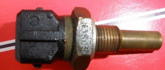
Appearance of the device
You should not ignore a breakdown of the fuel level sensor (FLS), because in the absence of information about the remaining amount of fuel, you run a high risk of not getting to the gas station, but stopping somewhere in the middle of nowhere.
Where is the fuel level sensor located?
To understand why the fuel sensor shows incorrectly or does not work at all, you need to find out where it is located.
True, there is no special secret here, because naturally it is located directly in the fuel tank. The only difference that may be is the version of its execution. Depending on the design, it can be built into the fuel module, which is a single device consisting of a fuel sensor, check valve, fuel pump and filter (for injection engines), or installed separately in the middle/side of the gas tank separately, or screwed into a separate device by a separate device. tank if it is a diesel car.
Dut vaz 2109 injector high panel
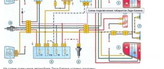
We present two diagrams for connecting the fuel level sensor of VAZ 2108, 2109, 21099 cars and their modifications with a carburetor engine.
Electrical diagram for connecting the fuel level sensor for VAZ 2108, 2109, 21099 cars with mounting block 17.3722 and a “low” instrument panel (before 1998 onwards)
Electrical diagram for connecting the fuel level sensor for VAZ 2108, 2109, 21099 cars with mounting block 2114 and a “high” instrument panel (after 1998 onwards)
Features of the fuel level sensor connection diagram
Notes and additions
— The fuel level sensor (FLS) of VAZ 2108, 2109, 21099 cars is installed in the gas tank on the fuel intake. It is a float rheostat that changes its resistance depending on the position of the float. Read more: “Fuel level sensor for VAZ 2108, 2109, 21099 cars.”
Appearance of the device
You should not ignore a breakdown of the fuel level sensor (FLS), because in the absence of information about the remaining amount of fuel, you run a high risk of not getting to the gas station, but stopping somewhere in the middle of nowhere.
Types of fuel level sensors
Cars can use one of three main types of fuel level sensors. Namely:
- Lever. Refers to the type of float sensors. This is the oldest and simplest type of this device. It consists of a potentiometer (rheostat - variable resistor), a lever, and a float suspended on it. The advantage of a float sensor is its simplicity and reliability of design, as well as its low price. The disadvantage is the large error of the device. In addition, when the car is driven on an uneven road, the instrument needle on the panel often fluctuates, thereby reflecting the movement of fuel in the tank.
- Tubular. It is also float-operated. The design consists of a hollow tube, a float, a guide post, a signal wire (or wires) and a contact group. Provides a fairly high accuracy of fuel level readings, since the float is located in a limited space (inside a hollow tube). A fairly common model of fuel level sensor.
- Electronic. This is the newest type of sensor installed on modern cars and has its own control unit. Its other name is non-contact, which is due to its operating principle. Thus, the operating lever is directly located on the surface of the fuel, and the reading device is connected to it via a magnetic field. The error of such devices is minimal and does not exceed 1%, and often much less.
Please note that even modern sensors are dependent on the quality of the contacts on the connectors (in particular, operating and maintenance conditions). Therefore, any of the listed types of FLS can fail.
The FLS is working properly. What to do?
Try the following activities.
- The sensor connector has a pair of wires - pink and blue;
- The pink one controls the arrow of the fuel level indicator in the tank, and the blue one is responsible for the critically low fuel level indicator;
- Take any jumper at hand, that is, a piece of any wire, and then use the jumper to short the pink wire to ground, while turning on the ignition. At this moment the arrow should be in the full tank position;
- Now, similarly, using a jumper, we connect the blue wire to ground. This should turn on a light that indicates on the dashboard that the fuel level inside the gas tank is low;
- If, when the jumper is shorted to ground, the indicator or lamp does not work, this indicates that the indicator itself is “covered”, or there is a problem with the condition of the wiring.
There is absolutely nothing complicated about replacing the sensor. Dismantling work can be completed in 30-60 minutes with even a little experience. As for the FLS itself, it does not fail very often, but every owner of a VAZ 2109 and more should know about the features of its replacement.
Operating principle of the fuel level sensor
Depending on the principle of operation of the sensors, the malfunctions that may occur with them will differ slightly. Let's look at the operating diagram of each type of fuel level sensor.
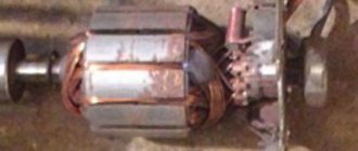
Float lever FLS
The operating principle of a float-type level sensor is based on the use of a rheostat. A lever is attached to its central part, at the end of which there is a float. Depending on the fuel level in the tank, the float will move, moving the rheostat lever accordingly along the contact path. During such movement, the resistance will change, which is recorded by the vehicle's electrical system. Accordingly, the arrow on the instrument panel will move in accordance with the indicated resistance on the rheostat. By the way, at a certain position of the float, and therefore the resistance value on the rheostat, a warning lamp on the dashboard will light up, indicating that there is little fuel left in the tank and refueling is necessary.
For clarity, let’s look at the operation of the fuel level sensor using the example of VAZ-2108/VAZ-2109, VAZ-21099 cars. Their design can use two sensors - for a high and low dashboard. They are structurally similar, but have different operating resistance. Specifically, for a high panel sensor, a resistance value between 238 and 262 ohms means the fuel tank is empty. With a resistance of 59...71 Ohms, the fuel gauge needle is approximately in the middle (accordingly, the tank is half full). If the resistance is within 17...23 Ohms, then this means that the car’s tank is completely filled.
As for the sensor for the low panel, the situation is similar. So, with a resistance of 285...335 Ohms, the arrow points to an empty tank. At 100...135 Ohms, the arrow will correspond to half, and at a value of 7...25 Ohms - at the end of the scale, pointing to a fully filled tank.
The specified resistances are important in the context of testing the sensor, since if it fails, the first thing to do is to check the internal resistance of the sensor using an electronic multimeter.
Please note that the indicated resistance values are relevant only for the listed VAZ models. For other machines, the corresponding values must be looked for additionally in the technical documentation (manual) attached to them. However, even these indicators can be used as a guide!
Tubular FLS
The design of the sensor is based on a housing with a guide post (actually a tube), at the other end of which there is a wire with a contact group (chip). The design also includes a float with slip rings located inside a hollow tube. The housing flange is secured using mounting bolts on the top wall of the fuel tank. By the way, this is a disadvantage of this type of sensor and imposes a limitation on its use. In particular, tubular type sensors can only be installed on tanks whose height is sufficiently large.
The operating algorithm of the tubular fuel level sensor is as follows:
- On the tube that touches the bottom, in its lower part, there is a hole (or two) through which fuel enters inside.
- The float located inside the tube has contact rings and when moving through the tube, as the fuel level in the tank changes, the resistance also changes. Resistance is measured using one or two contact wires located along the guide tube.
- The movement of the float on the surface of the fuel naturally changes the value of electrical resistance on the contact wire when power is applied to it.
- At the moment when the float is in the upper position (the tank is completely full), a small section of the contact wire is activated, and accordingly, the resistance value is minimal. At the moment when the tank is empty, the float is at the lower extreme point, respectively, the length of the signal wire is maximum, which also corresponds to the maximum electrical resistance.
The resistance of the fuel level sensor will differ for different cars, so when measuring you need to use technical documentation.
Electronic FLS
Electronic fuel level sensors are installed on cars that use high-quality gasoline and diesel fuel produced on a biological basis. This not only provides very accurate sensor readings, but also allows the actuator to “avoid touching” the fuel directly. However, the peculiarity of using such sensors is that it does not provide smooth monitoring of the fuel level (in small steps). The design of contactless FLS is based on an inactive magnetic sensor. The diagram of the fuel level sensor according to which it works is as follows:
- The main part of the sensor is located in a sealed housing. Only the magnetic sensor (MAPPS) and its lever are in contact with the fuel.
- The movement of the float with a magnet occurs along a sector defined by metal plates of different lengths. A signal corresponding to a certain fuel level in the tank is generated depending on the position of the magnet on a separate plate.
The fuel level indicator in this case is formed using a discrete method since the amplitude of the feedback signal will change from segment to segment that the magnet passes through. Depending on the model of a particular sensor, the signal amplitude and other technical information differ. The operating error of such a system does not exceed 0.5%...1%, but the cost is also significantly higher than a conventional contact system, so these FLS data are installed only on business and premium class cars.
FLS installation process
FLS installation is carried out by partners in 100% of cases. Clients, as a rule, do not have the qualifications, experience and desire to install FLS on their own. The reasons for reluctance are not only technical, but also organizational and social (obstruction of innovations in control, sabotage and vandalism of drivers, etc.).
To install the FLS you must have:
- A team of 2 people (it is difficult for one person, for example, to dismantle the tank)
- Tools Bimetallic crown for metal (often with a diameter of 35mm)
- Angle drill
- Metal drills (often titanium nitride, yellow)
- Phillips and slotted screwdrivers
- Pliers (nippers, pliers, etc.)
- Hacksaw or pipe cutter
- Riveter (for securing the FLS to thick-walled tanks)
- Calibration equipment Calibration tube
As a rule, professional installers have a special technical vehicle. It contains tanks for draining fuel and a station for pumping fuel.
In addition to equipment, you need to have theoretical training and experience in solving non-standard situations.
Now let’s take a closer look at the installation process of each type of FLS.
Ultrasonic FLS
To install, you need to clean the area outside the bottom of the tank, glue the FLS there and secure it with a clamp placed around the tank. After this, the power supply is connected to the FLS and calibration is performed.
- The ultrasonic FLS is installed externally at the bottom of the fuel tank. For installation, the geometric center of the tank bottom is selected.
Operating time is approximately 4 hours.
Capacitive FLS
To install a capacitive FLS, you need to remove and evaporate the fuel tank, make a hole at the top of the tank, insert the measuring part of the FLS into it and secure the FLS with self-tapping screws to the surface of the tank. After this, the power supply is connected to the FLS, calibration and calibration are performed.
- Before installation, all fuel must be drained from the tank. Then you need to get rid of the fuel vapors remaining in the tank after draining the fuel. If this is not done, then when drilling a hole, an explosion will occur due to a spark (especially after using gasoline). To do this, the tank is dismantled, water is poured into it, drained (repeat), and then evaporated (the process is called “tank evaporation”).
- For installation, the geometric center of the tank is selected.
- A hole is made in the geometric center of the tank; metal shavings should not fall into the tank.
- The measuring part of the FLS is cut slightly shorter than the height of the tank - this way fuel can freely flow between the tank tubes. For trimming, use a pipe cutter or a hacksaw.
- Calibration in progress. This will allow the FLS to know its new length after trimming. To do this, the FLS is turned over with the measuring part up and completely filled with fuel. After 1-2 minutes, the fuel is drained.
- The capacitive FLS is installed in the hole made so that the measuring part is inside the tank, and the board with the interface cable is outside.
- The sensor is fixed to the surface of the tank with self-tapping screws. There are holes in the metal base of the top of the sensor on which the board is attached for self-tapping screws.
- The FLS is connected to the vehicle's on-board electrical network and to the computer. A special adapter is used for this. Software for setting up the FLS is installed on the computer.
- Calibration is in progress.
- The FLS is disconnected from the computer and connected to the tracker. Tracker installation is complete.
Operating time is approximately 4 hours. Training video from Omnicomm (10 minutes)
Connection to CAN bus
To connect to the CAN bus, you must first find it in the car. The CAN bus is two wires twisted into a twisted pair. There are many wires in a car, and there may be more than one CAN bus. Therefore, it is very difficult to find the right CAN bus without documentation about where it goes.
When it is found, a “CAN crocodile” is used to read the data (recommended) or connected directly to copper wires (less preferable).
Fuel level sensor malfunctions
Externally, malfunctions of the fuel level sensor manifest themselves in one of the following situations:
- the arrow on the device is constantly in motion, twitching, jumping to extreme positions;
- when the fuel tank is full, the arrow indicates that it is partially filled or that it is completely empty;
- when the ignition is turned on, the needle on the instrument is at the zero mark, provided that there is guaranteed to be fuel in the tank;
If you have similar problems, it means that the fuel level sensor is not working, but if the needle movement does not drop to zero, and the minimum residue signal lamp does not light up or, on the contrary, lights up even when the tank is full, then this indicates a malfunction of the instrument panel itself.
On cars controlled by an ECU, you can find out about the presence of problems with the FLS by the error codes recorded in the RAM block; to do this, just connect a diagnostic scanner to read the memory and check the parameters of the sensors of various systems.
Fuel level sensor errors
The numbers of the main errors that correspond to malfunctions of the fuel level sensor:
- P0460 - “FLS electrical circuit malfunction.” In practice, this means damage or breakage of the power and/or signal wire. Often this is simply a deterioration of contacts due to their oxidation.
- P0461 - “Signal level out of acceptable limits.” An error is generated if the signal from the fuel level sensor is too weak or too strong. This may also be accompanied by interruptions in the fuel supply to the engine, and as a result, a decrease in its power up to a complete stop.
- P0462 - “Low signal level in the FLS circuit.” Usually the error is formed as a result of corrosion of contacts, open ground circuit, short circuit in the circuit, damage to the fuel tank (fuel leak).
- P0463 - “High signal level in the FLS circuit.” As a rule, the error is formed as a result of damage to either the fuel level sensor itself or its float. There are known cases when it occurred due to the fuel tank rusting.
- P0464 - “Unreliable contact in the FLS circuit.” The error is formed as a result of damage to the insulation on the wiring, oxidation of the contacts, interruptions in the transmission of the signal from the sensor to the electronic control unit.
Signs of trouble
FLS failure does not happen often, but at some point it can take the driver by surprise. Incorrect gasoline readings can result in the car owner overfilling the car tank at a gas station or running dry on the road.
Although a breakdown is a rare occurrence for this device, it becomes immediately noticeable to the car owner. The appearance of problems with FLS manifests itself in a car as follows:
- The arrow, which shows the amount of gasoline in the gas tank, constantly remains at zero, even when refueling the car;
- The arrow indicates overestimated indicators. For example, a full tank is shown when it is only half full;
- The arrow indicates underestimated indicators. For example, when filling a full tank, the dashboard displays much less.
It is not necessary to get a new device if these problems arise. In some cases, it is possible to adjust it and resolve inaccuracies.
Causes of malfunction
The reasons why the fuel level sensor does not work or it shows incorrectly are the following faults:
- The float has lost its seal. This situation is relevant when a ball made of fragile plastic is used as a float, which can crack as a result of mechanical stress or as a result of operating the car in severe frosts. In this case, the float will be inside the liquid or, more often, it will simply sink and fall to the bottom. The result will be a constant reading from the device that there is no fuel in the tank. Repair measures include replacing the float or the entire assembly. Another rare option is that the float can simply detach from the lever on which it is attached and “go off on its own.”
- Deformation of the lever that holds the float. As a result, the float may lose mobility or reflect incorrect information. Often this situation occurs when the fuel module is inaccurately removed from the tank, but sometimes even as a result of long-term operation of the car on roads with uneven surfaces, that is, with constant vibrations while driving. You can try to return the lever to its original shape, but most often the corresponding lever is simply replaced with a new one.
- Damage to the sensor housing. As a result, the readings of the resistive elements may change or the lever that takes the corresponding readings may be damaged. In this case, the reason why the sensor does not show the fuel level correctly is the use of low-quality gasoline or mechanical shock loads on the part.
- Failure of resistive elements. This is a fairly common reason why the fuel level sensor does not work. Elements on the rheostat fail for natural reasons, that is, as a result of abrasion during long-term use. It is possible that the wear is partial, for example, in the middle. In this case, the instrument needle will twitch. It is also possible that there is no contact between the sliding element and the resistive track due to damage or wear of the resistive coating or loosening of the slider foot pressure. With such a malfunction, the arrow will lie at zero.
- Lack of electrical contact in a certain section of the circuit. As a rule, on contacts that are oxidized either by moisture or fuel. The wires, their insulation, or breakage may be damaged. There are also sometimes problems with electrical connectors.
- The signal wire has a short to ground. In this case, the value of its resistance will be distorted and tend to zero. With such a malfunction, the level sensor incorrectly displays the level, transmitting information that the tank is completely filled.
- The fuse responsible for the operation of the fuel level sensor has blown. The fuse number must be found in the electrical diagram of the specific vehicle.
- Failure to secure the sensor on the fuel tank body. For example, with a skew. As a rule, in such a situation, the smell of fuel spreads outwards, in particular, the smell of gasoline will be heard in the cabin.
- There are cases when the resistive board on which the slider moves simply falls off the fastening solder.
- Tubular fuel level sensors may have a broken signal wire. In this case, the arrow will constantly show an empty tank.
- Also, tubular sensors are characterized by a coating that can form on the guide post. This will naturally make it difficult (and even impossible) for the float to move. Plaque is usually formed as a result of using low-quality fuel (with a large amount of paraffin, gasoline instead of gasoline). In this case, the instrument needle will freeze in one position, and not necessarily in one of the extreme ones.
- For non-contact sensors, the magnetic sensor and/or its wiring may be damaged. Some of them have a special control and control board installed. The problem may be with her too. In this case, the sensor usually fails completely, that is, it does not indicate the fuel level at all.
Most often, problems arise with floats or resistive elements, which wear out over time and stop transmitting correct data. But note that when the fuel level is not displayed, it is not always the sensor that is to blame. Often the arrow does not work, and here the device on the panel, which, in fact, is a potentiometer, is to blame. Therefore, if the fuel sensor does not indicate the fuel correctly, then you need to remove it and check it with a multimeter and make a visual inspection.
Functionality check
The VAZ 2109 fuel sensor can be checked for functionality using an ohmmeter or multimeter. After the device is removed from the gas tank, its contacts should be connected to the tester. We fix the float in one position and look at the indicators. The result should be 275-320 Ohms in the upper position of the float or 5-20 Ohms in the lower position. In the middle the resistance indicator is 100-130 Ohms. These figures are for a low instrument panel.
For a high panel these values are different:
- 260-280 Ohms in the lower position;
- 60-70 Ohm - average value;
- 15-20 Ohm is the upper limit position of the float.
If the device’s performance corresponds to the examples given, the device is working, everything is in order with the sensor, and it does not need repair or replacement. When significant deviations are present, it is worth checking the integrity of the wires. If they are ok, the sensor itself is faulty and needs to be replaced.
How to check the fuel level sensor
The first thing to do when checking any fuel level sensor is to check whether power is supplied to it through the fuse. If the design of the car does not allow open access to the sensor, then you need to use the car's electrical circuit and connect to the corresponding terminals on the blocks. To do this you will need to use pieces of wire. If there is access (usually through the trunk or under the rear seat), then you need to disconnect the chip from the sensor and then use an electronic multimeter to check or test.
To understand which contacts you need to connect to, use the wiring diagram, but if you are dealing with a conventional resistive level sensor of an injection car, then as a guide you can look at the cross-section of the wires suitable for the block - the wires for the fuel pump are always thicker than for the sensor. In general terms, the verification algorithm will be as follows:
- With one tester probe, touch the positive terminal on the chip, and with the other, touch the negative terminal or the body of the car (it is advisable to choose a place where there is either no paint coating at all or it is minimal).
- If power comes in, the multimeter will show +12 Volts (in standard passenger cars).
If there is no power, first you need to check the integrity of the fuse, and then the integrity of the plus and minus wires. When there is power, but the fuel sensor shows incorrect data, you need to continue checking and make sure what the problem is - in the sensor or wiring.
Checking the fuel level sensor using the universal method
After checking whether power is supplied from the fuse to the fuel sensor, it is necessary to check both the operation of the sensor itself and the signals sent from it to the potentiometer on the dashboard, that is, the fuel level device.
There are three wires between the fuel sensor and the potentiometer used in cars with a carburetor engine. One of which is “ground”, the second is the resistance signal wire going to the device, and the third is the signal wire to the critical fuel level warning lamp!
There are four wires between the sensors and potentiometers on injection motors. The first is “ground”, the second is power to the fuel pump, the third is signal, the fourth is to signal lamp. There are also three wires between the electronic sensors and the device. The first two are power and ground, and the third is a signal going to the control unit, which will indicate the amount of fuel on the digital display of the dashboard.
When checking a float or tubular fuel level sensor, it makes sense to start with a universal method. It is performed in two versions - when the arrow is constantly at the beginning of the scale and when the arrow is constantly at the end of the scale. Let's start with the first one. To do this you need:
- Provide access to the sensor contact group on the fuel tank.
- Turn on the ignition.
- Break the signal wire circuit (using additional wires).
- Observe the behavior of the level indicator on the instrument panel.
If after this the arrow on the device moves to the end of the scale, the fuel level sensor is faulty. If the arrow remains in place, you need to check the integrity of the signal wire, that is, “ring” it.
If the arrow is constantly at the end of the scale, then the sensor is checked according to the following algorithm:
- Provide access to the sensor contact group above the gas tank.
- Turn on the ignition.
- The end of the signal wire going to the tidy is alternately shorted first to the sensor contact, and then to the body (“ground”).
- If the instrument needle remains at the zero mark in both cases, this means that, most likely, the signal wire connecting the sensor to the instrument has broken. Therefore, it needs to be called.
- If the arrow deviates in the opposite direction if the wire is shorted to the body, it means there is no contact of the sensor with ground.
- If the arrow moves in both cases, it means that the sensor is faulty and further diagnostics are required.
For more accurate diagnostics, it is better to check the fuel level sensor when it is removed.
During dismantling, make sure that debris from the cap or seal rim does not fall into the fuel tank. Therefore, before dismantling, it is advisable to wipe off the dust and dirt on the fuel module cover with a rag.
How to check a lever fuel level sensor with a multimeter
We will consider a specific example of how to check a float-type lever fuel level sensor in a removed state based on the VAZ-2108, VAZ-2109 and VAZ-21099 cars. The verification algorithm will be as follows:
- Turn on the multimeter in resistance measurement mode.
- We connect probes to the sensor terminals and move the resistive lever along the track. The resistance under different modes should gradually change.
- So, if the correction hangs below under its own weight (corresponds to an empty tank), then the resistance on the sensor should be in the range of 238...262 or 285...335 Ohms, depending on which sensor is used. If you raise the float down, the resistance should drop to 17...23 or 7...25 Ohms. In practice, the indicated values may differ SIGNIFICANTLY. If the readings differ significantly, do not change, or change abruptly as the float moves, the sensor is most likely faulty.
In addition to measuring the fuel level sensor with a multimeter, you also need to perform a visual check of it. In particular, you need to check the functionality by making sure that the wires and connectors do not have mechanical damage. It is also necessary to inspect the presence of oxides and/or debris on the variable resistance, and the strip with contacts is securely fastened and soldered to the terminals. You also need to check the contact density, that is, how tightly the “tongue” fits the variable resistance. If necessary, it will need to be bent (just be careful!).
On other cars (or when using other sensors), the verification algorithm will be the same, but you must first know the nominal value of the resistance of the installed sensors. This can be found in the instructions for them or in the technical documentation for the car (manual).
Please note that if the fuel level sensor is working, but the indicator on the dashboard still does not work correctly or does not work at all, it means that the indicator itself is faulty. Often repairs involve replacing (or adding) a trim resistor. This is required in order to correct the failed resistance on the device itself.
Gasoline sensor for VAZ 2109 (carburetor, injector)
If suddenly the fuel gauge needle drops down or behaves somewhat inappropriately, there is no need to worry too much. You can easily fix the problem yourself if it is a faulty sensor.
Appearance of the device
You should not ignore a breakdown of the fuel level sensor (FLS), because in the absence of information about the remaining amount of fuel, you run a high risk of not getting to the gas station, but stopping somewhere in the middle of nowhere.
Location
If usually most repair work related to the engine and its system is carried out through the engine compartment, then in the case of the fuel level sensor everything is somewhat different.
FLS location
Reasons for replacement
You will definitely have to replace the sensor if the car starts to produce the following:
- The fuel level indicator needle “dances” or has fallen dead to the zero position;
- The indicator is constantly on, indicating a critical fuel level, although you have just filled the tank full.
FLS diagram
FLS on high and low panels
The differences in the sensors on the injectors and carburetors are minimal. Also, the fuel level sensors on VAZ 2109 cars equipped with a low and high panel are slightly different.
The difference lies in the resistance indicators. These parameters must be known when checking the condition of the sensor resistor.
Panel type
Resistance readings
In this regard, when buying a new fuel level sensor, be sure to ask for a controller for a high or low panel, depending on what kind of car you have. It is also important to note that in the case of injection engines, the sensor is located inside the fuel pump, but it is based on the same operating principle as a carburetor one.
Functionality check
Do not rush to throw out the old sensor and replace it with a new regulator. First you can try to check if it really doesn't work.
To check, you will have to extract the “suspect” in any case.
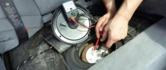
- Inside the car, remove the lower part of the rear seat, remove the soundproofing material, if any. This will give you access to the inspection hatch in the floor of the car.
- Using a Phillips screwdriver, unscrew the four mounting screws that hold the hatch in place. Take it off. Under the hatch you will find a sealing gasket made of rubber. In any case, even if the old sensor works again for the benefit of your car, this gasket should be replaced.
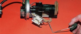
- Disconnect the power supply block with wires from the sensor, and then unscrew the fastening nuts around the perimeter that hold the desired fuel level sensor on the tank body. Usually there are 6 of these nuts, and to dismantle them you will need an 8 socket socket or a regular wrench.
- Under one of the nuts there is a ground wire attached to a stud. Remove the wiring and put it aside for now. He shouldn't interfere.
- Carefully remove the sensor and do not forget to remove the rubber sealing gasket, which is located directly under the regulator. If there are signs of damage or defects on it, be sure to replace this component.
- When the sensor is removed, visually check its current condition. If there are mechanical damages, there is no point in further trying to repair it or restore its functionality. Change it right away.
- If there is no visual damage, check the condition of the float. It can be depressurized, that is, there is fuel inside it, cracks and various defects through which fuel has leaked are visible on the surface of the element. If all of this is present at the float, replace the entire sensor.
- Be sure to blow out the fuel filter with compressed air. A useful event that definitely will not harm your fuel system. Especially if the quality of gasoline with which you fill your VAZ 2109 leaves much to be desired.
- Check the condition of the resistor. To do this, you will need a multimeter in ohmmeter mode. Connect a measuring device to the sensor terminals and take readings. In the lowest position (empty tank), the resistance should be about 315-345 Ohms. If the tank is half full, the resistance will be 108-128 ohms. And when the tank is empty, the ohmmeter should show no more than 7 ohms. If the parameters differ from those specified, or there is no resistance at all, this indicates a malfunction of the controller. It must be replaced.
Fuel level sensor repair
First of all, you need to understand that repairing the fuel level sensor is impossible without removing it from its seat.
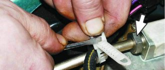
If the resistive elements on the lever fuel level sensor are worn out, you can try to bend the “tongue”, which directly slides over them and transmits the current value to the monitoring device. At the same time, you can clean the contact tracks of the device. If the resistive track has worn out significantly, then repair is not possible and the FLS must only be replaced. If a board with a resistive track “walks” in its seat, it needs to be soldered again.
When there is a malfunction in the electrical circuit of the sensor, problems usually occur at the contacts. Accordingly, they need to be cleaned and tightened. It is also advisable to lubricate them with a special lubricant. If the wires are damaged, it is advisable to replace them with new ones (you can use a whole bundle). However, if the damage to the insulation is minor, you can use electrical tape or heat shrink for wires for repairs.
If the guide tube in the tubular sensor is dirty, it means that it needs to be cleaned and the deposits washed off using a spray with a cleaner. At the same time, you can also clean the signal wires located along the tube.
The disadvantage of the electronic fuel level sensor is its non-repairability. At least in a garage environment. Therefore, if this unit fails, contact a car service center or an official representative of your car manufacturer for help.
Disassembly of the unit, its reassembly
To check the functionality of the VAZ 2108, VAZ 2109 sensor, it is necessary to disassemble the unit. You will need the following set of tools:
- screwdriver;
- key to 7;
- replaceable head for 10.
The following actions are performed sequentially:
- We recline the back seat and see the lid. Use a Phillips screwdriver to unscrew the fasteners and remove the compartment cover.
- There are a bunch of wires in the compartment, all of them must be carefully disconnected one by one so as not to damage them. This is where the 7 head comes in handy.
- Next, use a 10mm head to unscrew the fuel sensor itself, and then remove it from the gas tank. This should be done carefully, without jerking.
This completes all manipulations to disassemble the sensor assembly. Now the device can be cleaned, resistance checked or replaced. If there is external mechanical damage on the device body, you don’t even have to check it, but it is better to immediately replace it with a new one. The sensor cannot be repaired, just like its spare parts. Assembly is carried out in the reverse order, without any changes. Before connecting the wires, it is advisable to check their integrity. This is all that may be needed when dismantling the unit.
Purchasing new equipment
Repairing old equipment is not difficult if it has become unusable due to oxidation or rust formation. Wiping the device can help restore contacts, but if the device is broken, even after restoration it may display incorrect data. If the error is more than 10%, then this can significantly affect the driver’s comfort behind the wheel, as well as the risk of being left with an empty tank on the road.
Therefore, if there is an error, it is recommended to replace it with a new device. Thus, the car owner can be confident in the accuracy of the data displayed on the dashboard. The cost of spare parts is relatively inexpensive; an injector can be found within 300 rubles. The part is easy to maintain and does not require replacement often, so it is recommended that if the data is inaccurate, replace it immediately.
Purchasing new equipment ensures that correct readings are displayed. By purchasing original spare parts, the car owner can forget about replacing them within 2-3 years.
Sources
- https://artel55.ru/diagnostika-i-remont/zamena-datchika-urovnya-topliva-vaz-2109.html
- https://k-SportRacing.ru/neispravnosti-i-remont/ne-pokazyvaet-uroven-topliva-vaz-2109-inzhektor.html
- https://adm-maisk.ru/shumoizolyaciya/dut-vaz-2109-inzhektor.html
- https://moto163.ru/tyuning-i-servis/datchik-topliva-vaz-2109-inzhektor.html
- https://lemzspb.ru/provod-dut-vaz-2109/
- https://RetroTruck.ru/obsledovanie-i-remont/nepravilno-pokazyvaet-uroven-topliva-vaz-2109.html
- https://luxvaz.ru/vaz-2109/356-datchik-benzina-karbyurator-i-inzhektor.html
- https://7road.ru/drugoe/datchik-urovnya-topliva-vaz-21099.html
- https://ladafakt.ru/datchik-urovnya-topliva-vaz-2109-inzhektor.html
- https://linhai-russia.ru/remont/datchik-topliva-vaz-2109-inzhektor-2.html
- https://toyota-chr2.ru/polomki-i-remont/zamena-datchika-urovnya-topliva-vaz-2109-karbyurator.html
[collapse]
Location
If usually most repair work related to the engine and its system is carried out through the engine compartment, then in the case of the fuel level sensor everything is somewhat different.
The FLS is located under the rear seat. To access it, you need to remove the seat, bend back the soundproofing material, if any, and find the controller we need in the area above the fuel tank.
FLS location
Post navigation
Why does the voltage drop in the on-board network of the VAZ 2114?
Source
|
|
Idle speed adjustment
The second setting of the VAZ-2109 carburetor is idle speed, it can be partial or full. The first is for minor speed adjustments, the second is for adjusting the amount of air (setting CO emissions in the exhaust gases).
Partial adjustment is performed using the air-fuel mixture “amount” screw. This screw sets the opening angle of the throttle valves, which ensures that the air-fuel mixture enters the cylinders when the accelerator pedal is released. The “quantity” screw rests on the throttle valve control lever and when screwed in, it pushes the lever, causing the valves to open slightly.
Partial idle adjustment is performed with a warm engine and creating a load on the vehicle's on-board network by turning on the high beam headlights and the interior heater at full power. The adjustment is carried out with the engine running by screwing in/unscrewing the “quantity” screw until the optimal idle speed is established, which for the VAZ-2109 is 800-900 rpm (this can be tracked using a standard or plug-in tachometer).
If it is not possible to set the required speed or the motor operates unstably at it, a complete adjustment is made, which is made by two screws - “quantity” and “quality”.
The algorithm for this adjustment consists of the following stages:
- Warm up the engine and then turn it off;
- We find the quality screw (it may be closed with a plug that will have to be removed), screw it in until it stops, and then unscrew it 3-4 full turns;
- We start the engine, turn on electrical consumers (lighting and stove) to create a load in the on-board network;
- By rotating the “quantity” screw, we achieve 700-800 rpm on the tachometer;
- By turning the “quality” screw, we set the maximum possible speed (they will increase to a certain level, and then stop. The moment the speed increase stops is considered the maximum);
- We set the “quantity” screw to 900 rpm;
- Using the “quality” screw we lower them to 800 rpm;
- We slowly tighten the “quality” screw until interruptions appear in the operation of the power plant, after which we unscrew it back 1 turn;
- We adjust the speed with the “quantity” screw, bringing it to a normal value - 800-900 rpm;
After the adjustment operations, we check that they were carried out correctly. This is done by sharply pressing the gas pedal and then quickly releasing it. With a properly configured carburetor, the engine should respond quickly to pressure, without any failures or hesitations. And after releasing the pedal, the speed will drop to the idle level, without sags or instability of the engine.