1200 rub. for the photo report
We pay for photo reports on car repairs. Earnings from 10,000 rubles/month.
Write:
Errors P0113 indicates a failure of the intake air temperature sensor . That is, a high signal level from the IAT sensor (also known as the temperature sensor of the incoming air into the engine) is detected. On some engines this is a separate sensor, but basically, it is nothing more than a DBP (absolute pressure sensor) or a mass air flow sensor with a pressure sensor inside.
Code P0113: indicates that the Intake Air Temperature Sensor High is producing a high signal.
The intake air temperature sensor is installed in the air pipe and is a thermistor. The resistance of such a sensor changes depending on the temperature, and the control unit, taking into account this behavior and the corresponding signal, adjusts the pulse width supplied to the injectors, which as a result affects the amount of fuel supplied, and also changes the ignition timing and controls idle speed. The readings of the IAT sensor are especially important when starting the engine, since, together with the coolant sensor, their mutual resistance provides accurate information for determining the injection time (avoiding problems when starting the engine hot). That is why, when a problem appears with the intake air temperature sensor and it stops proportionally changing its resistance, error P0113 — Intake Air Temperature Sensor High — appears, which can be determined by diagnostics. If no data is received from the sensor at all, then error P0110 is recorded.
What is an intake air sensor and where is it located?
The intake air temperature sensor (abbreviated as ДТВВ, or IAT in English) is needed to adjust the composition of the fuel mixture supplied to the engine. This is necessary for normal operation of the motor in different temperature conditions. Accordingly, an error in the intake air temperature sensor into the manifold threatens excessive fuel consumption or unstable engine operation.
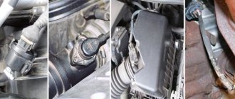
DTVV is located on the air filter housing or behind it . It depends on the design of the car. It is performed separately or can be part of the mass air flow sensor (MAF).
Places where the intake air temperature sensor is located
Intake air temperature sensor malfunctions
There are several signs of a malfunctioning intake air temperature sensor. Among them:
- interruptions in engine operation at idle (especially in the cold season);
- Engine idle speed is too high or low;
- problems with starting the engine (in severe frosts);
- reduction in engine power;
- excess fuel consumption.
Malfunctions may be due to the following reasons:
- mechanical damage to the sensor caused by exposure to solid particles;
- loss of sensitivity due to contamination (increased inertia of transient processes);
- insufficient voltage in the car's electrical system or poor electrical contacts;
- failure of the sensor signal wiring or its incorrect operation;
- short circuit inside IAT;
- contamination of the sensor contacts.
Checking and cleaning DTVV.
Checking the intake air temperature sensor
Before checking the intake air temperature sensor, you need to understand the principle of its operation. The sensor is based on a thermistor. Depending on the temperature of the incoming air, the DTVV changes its electrical resistance. The signals generated by this are sent to the ECM in order to obtain the correct fuel mixture ratio. Diagnosis of the intake air temperature sensor must be performed based on measuring the resistance and the magnitude of the electrical signals emanating from it.
The test begins with calculating the resistance . To do this, use an ohmmeter by removing the sensor from the car. The procedure is carried out by disconnecting two wires and connecting them to a measuring device (multimeter). The measurement is carried out in two engine operating modes - “cold” and at full speed.
Sensor resistance measurement
In the first case, the resistance will be high-resistance (several kOhms). In the second - low-resistance (up to one kOhm). The operating instructions for the sensor must contain a table or graph with resistance values depending on temperature. Significant deviations indicate improper operation of the device.
As an example, we present a table showing the relationship between temperature and resistance of the intake air sensor for the engines of the VAZ 2170 Lada Priora car:
| Intake air temperature, °C | Resistance, kOhm |
| –40 | 39,2 |
| –30 | 23 |
| –20 | 13,9 |
| –10 | 8,6 |
| 5,5 | |
| +10 | 3,6 |
| +20 | 2,4 |
| +30 | 1,7 |
| +40 | 1,2 |
| +50 | 0,84 |
| +60 | 0,6 |
| +70 | 0,45 |
| +80 | 0,34 |
| +90 | 0,26 |
| +100 | 0,2 |
| +110 | 0,16 |
| +120 | 0,13 |
At the next stage, check the connection of the conductors to the control device . That is, using a tester, make sure there is continuity of each contact to ground. Use an ohmmeter, which is connected between the temperature sensor connector and the disconnected connector of the control device. In this case, the value should be 0 ohms (note that you need a contact diagram for this). Check each contact on the sensor connector with an ohmmeter with the connector disconnected against ground.
Measuring DTVV resistance in Toyota Camry XV20
For example, to check the sensor resistance on a Toyota Camry XV20 with a 6-cylinder engine, you need to connect an ohmmeter (multimeter) to the 4th and 5th terminals of the sensor (see figure).
However, most often the DTVV has two thermistor outputs, between which it is necessary to check the resistance of the element.
We also bring to your attention the IAT connection diagram in the Hyundai Matrix car:
Connection diagram for DTVV with DBP for Hyundai Matrix
The final stage of the test is to find out the supply voltage at the connector . In this case, you must turn on the car's ignition. The magnitude of the electrical signal should be 5 V (for some DTVV models this value may differ, check it in the passport data).
The intake air temperature sensor is a semiconductor device. Accordingly, its configuration is impossible. It is only possible to clean the contacts, check the signal wires, and also completely replace the device.
Checking the mass air flow sensor
Before you start experimenting, take the time to read the service manual. It describes in detail what a mass air flow sensor on a VAZ 2114 is and how to replace it.
We are looking for a sensor. Open the hood and find the air filter pipe. The mass air flow sensor is located on it, which determines the flow of air passing through the filter. I will give several options on how to check the mass air flow sensor yourself.
- Disable the sensor. Disconnect the block with wires from the connector by pressing the latch located below. Start the engine (1500 rpm or more). The controller understands the shutdown of the mass air flow sensor as an emergency condition and prepares the fuel-air mixture based on the position of the throttle valve. Try driving a short distance. If the car accelerates noticeably faster, this indicates a non-working mass air flow sensor. I would like to note that in the disabled state for ECUs Y7.2 and M7.9.7. RPM doesn't increase!
- Replacing the controller firmware. The original ECU firmware could have been replaced with an alternative one. In such a situation, we do not know which algorithm is prescribed in the case of operation in the mode discussed in the first paragraph. The throttle valve has a stop under which you need to place a thin plate (about 1 mm) to raise the speed. Then you need to disconnect the chip with the sensor. If the sensor is faulty, the engine should stall. If the engine is running, then the reason is due to the firmware features: the IAC steps are written incorrectly.
- Voltage measurement. Testing gives good results when working with Bosch sensors. You will need a multimeter. Select the DC voltage measurement mode and set the maximum value to 2 V.
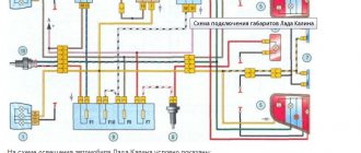
The connection diagram for the VAZ 2114 looks like this:
- yellow – incoming signal;
- gray with white – power output;
- green – grounding;
- pink with black – output to the main relay.
The colors may be different, but the sequence of connectors is the same.
Next, you need to turn on the ignition with the engine off. Connect the red (positive) probe of the tester to the yellow output, and the black (negative) probe to the green. Multimeter probes are inserted along the specified wires directly through the rubber seals of the connectors without damaging the insulation. For prevention, I recommend moistening the probes with WD-40. Intermediates or needles are not recommended due to the additional error they introduce. Measure the voltage. Compare the result with the table:
| Voltage, V | State |
| 1,01 – 1,02 | Good. The sensor is almost new and will last a long time. |
| 1,02 – 1,03 | Satisfactory. The sensor is old, but works properly. |
| 1,03 – 1,04 | Bad. The resource is almost exhausted. Will have to replace it soon. |
| 1,04 – 1,05 | Deplorable. The resource has been exhausted. Suitable for use if there are no alarming symptoms. It is advisable to replace |
| 1.05 – and above | Emergency. The sensor is faulty (possibly for a long time). Replacement is required. |
A newly installed sensor gives an output voltage of 0.996–1.01 V. Over time, it increases. A higher value means a higher percentage of wear.
Voltage data from the sensors is recorded by the on-board computer and can be viewed by selecting the appropriate group of parameters.
- Inspection and cleaning. Use a Phillips screwdriver to loosen the clamp holding the air intake pipe. We remove the corrugation and check whether there are traces of oil and/or condensation inside it, as well as on the inner surface of the sensor. Normally they shouldn't be there. The sensing element of the mass air flow sensor often breaks due to dirt getting on it. This can easily be avoided by regularly replacing the air filter. Reasons for oil getting into the air flow sensor:
- the permissible oil level in the crankcase has been exceeded
- The oil separator of the ventilation system is clogged
The sensor is attached to the pipe with two screws. We unscrew them with an open-end wrench (x10) and remove the sensor itself. There is an entrance at the front, which must be protected from the leakage of untreated air with an o-ring rubber seal. If it is missing or remains in the filter housing, dust clogs the sensor input grid. It needs to be cleaned, the seal installed, the leaks checked and the sensor put back in.
- Comparison with a working sensor. From personal experience, I was convinced that the most accurate test is to install a sensor that is known to work and compare the behavior of the engine with the “native” one.
In addition to the options considered for how to check the mass air flow sensor yourself, you can also contact a service center that has special equipment and carry out 100% diagnostics, for example, using the method of evaluating an oscillogram.
Intake air temperature sensor repair
How to repair an explosive temperature sensor.
The simplest type of IAT repair is cleaning . To do this, you will need some kind of cleaning liquid (carb cleaner, alcohol, or other cleaner). However, remember that you need to work carefully so as not to damage the external contacts .
If you encounter a problem where the sensor shows the wrong temperature, instead of completely replacing it, you can repair it. To do this, buy a thermistor with the same or similar characteristics as the thermistor already installed on the car.
The essence of the repair is to re-solder and replace them in the sensor housing. To do this you will need a soldering iron and the appropriate skills. The advantage of the repair is significant savings in money, because the thermistor costs about a dollar or less.
Main characteristics
The ambient temperature is read by an electronic thermistor. The VAZ-2114 is equipped with one of the following types of sensor:
You can purchase any of these options, as they are interchangeable. They can be made by different manufacturers, the price of this component is about 300 rubles, so it is impractical to repair it. In unclear situations, it is necessary to change the device.
The information from this device is read by an on-board computer, which reads pulses from the sensor and converts them into readings on the instrument panel. If you use a faulty sensor for a long time, the pulse from it may be read with an error, then the “Check” light on the dashboard will light up. A car enthusiast can look for problems for a long time until he notices a difference between the actual air temperature and the one shown by the sensor.
What does the ambient temperature sensor affect?
Car enthusiasts believe that the thermistor is a kind of device that only shows the temperature outside. In fact, this is not a simple thermometer. Since it is connected to the on-board computer, its readings slightly modify engine acceleration. The system has another sensor that measures the mass air intake. In this case, the external sensor does not affect the fuel supply too much; the engine will not stall.
If, when the controller is not operating correctly, the resistance in the circuit increases, the ECU will consider this a sign of a decrease in temperature. If there is a large difference in the readings, for example, when in summer the temperature sensor pulses are deciphered by the computer in the form of sub-zero temperatures, the fuel supply to the engine increases and at the same time the air intake decreases. Due to an incorrectly created fuel mixture, the engine will stall. On a VAZ-2114 this happens extremely rarely; usually it only increases fuel consumption, which the car enthusiast attributes to other reasons. Also at such moments, spark plugs flood, which is attributed to improper operation of the engine or other sensors. This makes it difficult to start the engine and leads to the need to change spark plugs.
Purpose and principle of operation
Many car owners are concerned about how much it costs to purchase such a sensor. It turns out that the DMRV 2114 has a considerable cost, it varies between 2-3 thousand. In this case, you can use both imported products and domestically produced parts. You shouldn’t be surprised that there are corresponding reviews about domestic models.
But you shouldn’t always trust reviews; it’s better to try the products in practice. Although you can find a lot of negative reviews about domestic sensors, they are more affordable.
This sensor allows the engine to operate in different operating modes, involving different loads. If we consider the operation of the device, it consists in creating a working mixture of air and gasoline. More precisely, the mixture includes gasoline vapors. The direct task of the product is to measure two indicators that are interconnected:
- Reaction time.
- The amount of air that is consumed for the reaction.
If the measurements are accurate, the device can determine what mixture the engine requires. This allows the system to obtain information about the required proportions. There are also situations when the sensor does not work correctly, producing incorrect values.
In this case, the mixture created in the system will not correspond to the current operating mode. As a result, power may decrease and consumption will likely increase. Among the possible consequences may be a deterioration in the dynamics of the car and a disruption in the response of the car.
Attention! The response of parts from different manufacturers may vary significantly. It is important to take this point into account when checking the operation of the sensor.
Ambient air thermistor faults
You need to look for the thermistor in the area of the left headlight, between the bumper and the radiator. Finding this element is the most difficult part of the replacement process, since its installation is as simple as possible - you need to pull out the old sensor from the chip and install a working one in its place. The body of the device is quite fragile, so there is no need to make excessive efforts.
The controller can fail for several reasons:
- damage from stones or soil while driving;
- climatic conditions (problems often arise during severe winters);
- wiring damage;
- oxidation of contacts due to moisture ingress.
Its malfunctions are related to the readings. This may be an incorrect temperature (7-10 degrees difference compared to the actual one) or sticking on the o. Motorists encounter the latter option even in summer.
What factors cause the mass air flow sensor to fail?
Most often, the device fails for reasons such as:
- Internal defects of the part;
- Oxidation of contacts;
- Poor wiring connection;
- Short circuit;
- Dust ingress;
- Filling with oil;
- Mechanical damage to the element.
Often, a malfunction of the mass air flow sensor occurs due to careless actions of the owner. For example, after careless washing of the power unit or during maintenance or repair. Failures associated with broken contacts or wiring can be corrected by cleaning the connections or repairing the break. Other problems usually require replacing the sensor. But if it becomes dirty with dust or oil, it can sometimes be cleaned. Most faults can be diagnosed by yourself. Some of them are visible during inspection, the rest are determined when checked by a tester. If self-diagnosis does not help you find the cause of the breakdown, it is recommended to contact a car service center.
How to set up the sensor
First of all, mechanics advise replacing the thermistor with a new one. In most cases, this is enough for the outside temperature to be displayed correctly. If this does not help, you can use one of the following tips:
- Check the contacts, if they are not oxidized, then you need to look at the sensor itself. You need to bend the legs on it a little.
- If the contacts on the chip oxidize, they need to be wiped with alcohol and dried. The best way to do this is to leave the car in the garage overnight.
- To check the wiring you will need a VAZ-2114 electrical circuit diagram. Start by checking the contacts in the X6 block of the mounting block (MB) on the motor side (usually the blue-red wire) in the 7th cell. Next, you need to check the contact in the 15th compartment of the MB block X4, located on the passenger compartment side. In the dashboard, testing is carried out in block X2, most often the conductor occupies 1 cell there (may vary depending on the year of manufacture of the car). According to the diagram, the “ground” is common with the headlight unit, so you need to look for it there. If there is no contact, then look for an open circuit.
If after replacement the sensor shows “-40”, then you need to remove the negative terminal from the battery for half a minute. This resets the computer and removes the error entry.
Removal and replacement
If the VAZ 2114 air sensor was checked, and the check confirmed incorrect operation, then you should think about replacing it. Experts do not advise rushing to throw away a part, even if it is not working correctly. Sometimes it happens that after cleaning the contacts it starts working again. It is worth paying attention to this possibility if you would not like to replace the part.
When it is not possible to revive an existing part, you should go shopping. A new part will not be cheap, it is an expensive pleasure. That is why experienced technicians advise initially checking the functionality of the old sensor before spending your savings. To replace the product, you will need to prepare a flat-head screwdriver, as well as a 10mm wrench.
The sequence of actions should be as follows:
- Initially, the ignition is turned off, the hood is opened, and the negative terminal is removed from the battery.
- Now you have to determine where exactly the sensor is located. Usually there are no difficulties with its location. In the engine compartment you can see the air filter unit; it is made of plastic. This sensor is located on its rear part; it is usually mounted on the air filter pipe.
- Next, the clamp made of metal is removed and the product is connected to a corrugated hose through which air is supplied.
- You will need to pull off the corrugated hose.
- Next, the contact block is removed, and it should be taken into account that there is a button on the bottom of the plug. When pressed, the spring wedge is released. This is necessary to freely pull out the block.
- A pre-prepared 10mm wrench is needed to unscrew the bolts one by one; they are used for fixing. By the way, the second of them is located on the lower part of the case.
- All that remains is to remove the sensor.
Temperature sensor VAZ-2114. Photo
In a modern metropolis, where there are a large number of cars, traffic lights, pedestrian crossings, traffic jams, and congestion, the car engine is subject to additional overheating, especially in the summer. In order to promptly respond to an increase in coolant temperature, a sensor is installed on the VAZ 2114. allowing you to control any changes in temperature.
By design, it is a resistor or thermistor, in which its resistance changes depending on the temperature. The installation is carried out in a constantly circulating flow of coolant occurring in the cooling jacket pipe, which is located on the cylinder block.
Due to the negative temperature coefficient of resistance of the thermistor, when the liquid is heated, its resistance decreases. So at a temperature of -40 degrees, it will be 100700 Ohms, when increased to +130, it will already be 70 Ohms. The controller supplies the sensor with a voltage of 5V through a constant resistance resistor located inside the controller.
The controller calculates the coolant temperature based on the voltage drop across the sensor. On a cold engine the voltage drop is high, on a warm engine it is low. Many control characteristics depend on the coolant temperature.
As soon as a malfunction occurs in the temperature regulator circuits, the controller, after a certain period of time, enters the corresponding code into its memory and begins to signal about the problems that have arisen using the “CHECK ENGINE” indicator lamp.
Replacing a failed coolant temperature regulator is not difficult, and all work on replacing it can be done independently, with your own hands, without the help of a mechanic.
Idle speed sensor VAZ-2114
The idle speed sensor or regulator on a VAZ-2114 car is designed to automatically adjust and stabilize engine operation during a short stop. It is a stepper motor and has a conical needle.
Located on the surface of the throttle body, not far from the throttle sensor. Fastening to the throttle body is done using two screws.
When the ignition is turned on, the rod extends completely and rests against the calibration hole located in the throttle pipe. Then, the sensor, counting the underlying algorithm, returns the valve to its original position.
On a warm engine at the time of adjustment, the regulator is located at 30-50 steps. The amount of air entering through the calibration hole constantly changes depending on the location of the rod.
Moreover, if the rod retracts, the pitch decreases, and vice versa. The stroke of the rod can be 250 steps. When purchasing a new idle speed sensor, the distance between the rod head and the flange is required; it should be about 23mm.
Camshaft position sensor
This mechanism is located near the cylinder block. The main task is to transmit data to the ECU regarding the current operating cycle. Among specialists, the mechanism is called a Hall sensor. The operation of the device is based on the following principle: in accordance with the location of the crankshaft, the position of the gas distribution mechanism is determined. The data received by the sensor is reported to the electronic unit. Fuel is injected and the mixture is subsequently ignited.
Air sensor VAZ-2114
Modern environmental requirements for internal combustion engines are increased. That is why, in all modes of its operation, the established ratio of air to fuel in the air-fuel mixture must be maintained.
Only if these conditions are met will the catalytic converter completely remove harmful substances in the exhaust gases.
To maintain the stoichiometric ratio of the various components present in the fuel-air mixture, reliably accurate information on the amount of air consumed is required.
The air flow sensor installed on the VAZ-2114 is designed to collect air flow data. The measure of intake air flow can be calculated both in volume and in mass.
Today there are two types of air flow sensor. thermal and mechanical.
With the mechanical method, the incoming air is measured, which is proportional to the movement of the damper. The basis of the thermal method is to measure the mass of incoming air, which directly depends on the temperature of the sensitive element for a given period of time. The car's air flow sensor is installed between the throttle valve and the air filter in the intake system.
Knock sensor, DTOZH, speed and others
In addition to the above mechanisms, other very important devices can be found in various corners of the engine compartment. The location of the VAZ-2114 injector sensors is quite chaotic, some are located directly on the power unit, others in other places - the gearbox, on electrical circuits.
Some equally important mechanisms include:
- The knock sensor is sensitive to various engine vibrations. Based on the received pulses, the ECU determines the qualitative composition of the mixture. Located on the cylinder block.
Engine temperature sensor - the only and simple, but extremely important task assigned to this device is to monitor the coolant temperature.
Speed sensor – from the name itself it is clear that this controller is necessary to measure the speed of a car. The DS transmits impulses to the ECU, which processes them and determines the speed of the car; the resulting result is displayed on the instrument panel by the speedometer.
Idling speed – not only reads information, but also corrects engine operation. DXH, using a special needle, controls the pipe - closes and opens. Due to this, the amount of oxygen supplied to the throttle assembly changes.
Mass air flow sensor - reads the data and transmits it to the control unit, which, based on the information received, determines the optimal ratio of the various components of the fuel-air mixture. A breakdown of the air flow sensor leads to the fact that the car significantly loses power, and the driver begins to feel a significant increase in the amount of gasoline consumed by the car.
These are the main and most significant sensors in the “fourteenth” system. It is also worth mentioning the FLS, which plays an important role - it determines the level of gasoline in the vehicle tank. Domestic drivers often experience difficulties with this device. Sometimes it works incorrectly and misinforms. But, as a rule, the FLS breaks down in old cars. You can repair the mechanism yourself, but it all depends on the severity of the breakdown.
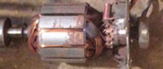
Crankshaft sensor VAZ-2114
The crankshaft sensor is installed on the oil pump cover at a minimum distance from the drive disk of the mechanism. Information coming from the position meter in which the crankshaft is located is received by the engine control system, through which the injection and ignition system is controlled.
Replacement of almost all types of sensors. installed on a VAZ-2114 car can be done independently, with your own hands; for this it is not at all necessary to take the car to a car service center. Watching the video will give you a clearer idea of the idle speed sensor.
Some cars of the tenth family were produced with trip computers, which were able to show the outside air temperature. With the advent of the VAZ 2115 and VDO dashboards with two windows, it became possible to display the temperature directly on the instrument panel. Let's consider various options for installing and connecting an external temperature sensor on a VAZ 2110 .
First of all, we need the external temperature sensor itself (DVT), suitable with catalog number 2115-3828210-03. Approximate price 150-200 rub.
You can check the DTV with a simple tester. As the sensor heats or cools, its resistance will change. The corresponding sensor resistances are in the instructions.
Now in order:
Installing an outside air temperature sensor
The main question: Where is it better to place the outside air temperature sensor ? According to the instructions, the DVT must be reliably isolated from moisture and direct sunlight. In addition, for accurate sensor readings, it is necessary to exclude exposure to heat from the engine compartment. It is allowed to slightly blow the sensor with a flow of oncoming air.
The standard mounting of the external air sensor is suitable for these conditions . which is located centrally behind the front bumper. Another good place for the DVT could be the towing eye in the bumper or a little higher behind the bumper on the left in the direction of travel.
The sensor has 2 contacts, one of which is “ground”, and the other is an information contact, which is most conveniently routed into the passenger compartment through the hole under the fuse block. Use a small piece of wire. Some people try to mount the outside air sensor in the rear bumper . In this case, as a rule, the temperature readings differ from the actual ones by 3..7 degrees. This is due to the warm air of the engine compartment, which passes under the bottom of the car.
Now that you have installed the wiring from under the hood to the interior, you need to connect the sensor:
Connecting the external air temperature sensor to the on-board computer of the VAZ 2110
“Dozens” were equipped with two types of trip computers (MK): MK-2112 (without indication of ECM error codes) and AMK-211001 (improved MK-2112 with error code indication). In accordance with the documentation, the second contact of the sensor must be connected to contact C4 of the MK block. And the existing wire from contact C4 should be pulled out and insulated.
If there is no external temperature sensor or there is an open circuit, the trip computer will show “—“.
Connect the DVT to the State, Gamma and Multitronics on-board computers according to the diagram that comes with the kit. If the DVT displays the temperature with an error, then you can use the temperature calibration function (not available on all BCs).
Connecting an outside air temperature sensor to a VDO panel with two windows
It is possible to connect DVT to VDO with 2 windows (luxury panels VAZ 2115). To do this, the wire from the sensor should be connected to block X2 of the instrument panel (red color of the block) to socket No. 1. If there is already another wire in this socket (fuel sensor in the tank), then the wires should be combined.
If there is no DVT or an open circuit on the VDO panel, the outside air temperature will be -40 degrees . Together with connecting the sensor, you can make a beautiful backlight for the VDO panel and change the color of the screens (photo report).
Now let's talk about the transition from the mass air flow sensor system to the DBP+DTV system. I’ll tell you in a nutshell why this is needed, what its advantages are and how it’s done. My brunette with red shoes has already checked out these two sensors and told me that she likes them, her mood has lifted and she made me very happy at the last races! True, she ate a little butter, so what now, she’s an athlete, and athletes need to be fed!
All serial VAZ injection cars have a mass air flow sensor - MAF. This is the most expensive sensor in the entire system. At the moment (07/15/2015) this sensor costs about 3000 rubles. It is quite expensive, not everyone can afford to buy it. The main task of this sensor is to calculate the air flow consumed by the motor. Based on the amount of air consumed, the ECU calculates the amount of fuel supplied. If the sensor shows high air consumption, then fuel consumption will correspondingly increase. If the sensor starts to “lie” and overestimate the air flow readings, then fuel consumption instantly increases. It turns out that the car “does not drive” and begins to “eat”. Now I’ll show you the “Max air flow sensor calibration” graph taken from the firmware.
Calibration of the mass flow sensor. Graph of air flow versus voltage. If suddenly the sensor begins to show a higher voltage than it should (up to 1.02V the mass air flow sensor should show, the new sensor shows 0.999V), then the ECU sees an increased air flow and begins to increase the injection time, thereby increasing fuel consumption. The gasoline just goes down the pipe, the spark plugs turn black, and the car doesn’t drive. What can we say about the poor animals who begin to breathe it.
Disadvantages of the MAF sensor: 1. High price. 2. High retardation of the sensor - it slowly counts the air, so the car stalls. 3. Not suitable for turbo engines. 4. Uneven XX on camshafts with an evil phase.
Advantages of the mass flow sensor: 1. After all, it counts the air, you can move around the city, the car is moving.
And now I will express my opinion about the combination of DBP sensors (absolute pressure sensor) + DTV (air temperature sensor). From the names of these sensors, it is not difficult to guess how the air entering the engine is calculated - by pressure and temperature. From these two data, you can easily determine the amount of air. DBP works quickly, measures pressure instantly, DTV measures temperature also quickly. The accuracy of the calculations depends on the correctly configured calibrations of these two sensors in the firmware.
Pros of DBP+DTV: 1. Smooth XX on camshafts with an evil phase (from 290g and above). 2. The cost is three times cheaper than the mass air flow sensor. 3. Instant responsiveness from the gas pedal, no dullness. 4. The motor works more elastically, air calculation is very fast, as a result the motor spins up faster and produces more power. 5. At XX, the engine is much quieter than at the mass air flow sensor (IMHO). 6. Suitable for turbo engines.
Disadvantages of DBP+DTV: 1. You cannot install DBP+DTV on the factory firmware; sports firmware is required. 2. You need straight hands and a clear head to install it. 3. You need to understand the firmware, or find a smart customizer.
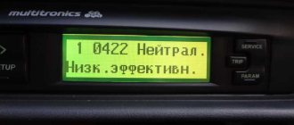
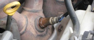
So, girls (write to me, I’ll help you with the firmware) and boys, let’s switch to DBP+DTV. I bought a DBP from Volga - 45.3829 (it is naturally aspirated, it is not suitable for a turbo engine) and used the DTOZH (coolant temperature sensor) as a DTV.
Here is the baby, small and distant Dadik.
But such a DTOZH will work as a DTV sensor.
Next, I cut off the MAF chip, exposed the wires and, in accordance with the diagram below, connected 5 wires going to the DBP and DTV. The wires on the MAF chip are numbered, which made the task very easy. The numbers on the DBP are also numbered. And for DTV, the 1st contact is the left one, and the 2nd one is the right one, if you look at the sensor contacts! Be careful, do everything carefully.