02/04/2022 159 199 117 VAZ 2115
Author: Ivan Baranov
Following the example of foreign automobile companies, it introduces advanced technologies into its vehicles. One such example is an on-board computer, designed to detect a malfunction in the machine using a digital code. We invite you to find out how the on-board computer of the VAZ 2115 is diagnosed - the error codes will also be deciphered in this article.
[Hide]
What does error 10 mean?
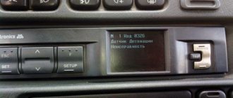
The driver of the VAZ 2114 sees error codes on the dashboard under the speedometer.
In the list of error codes 10 on the VAZ 2114, injector 8 valves do not exist. However, its appearance on the display is not uncommon. It means adding two known codes. To make sure that code 10 is not a glitch that arose as a result of errors stored in the computer’s memory, they can be reset by disconnecting the car’s power supply terminal from the battery. A de-energized control unit will clear the information stored in it. And if, while the car is moving, error 10 in the VAZ 2114 appears again, then you will have to understand its cause. For reference, we provide a table of codes 1-9, which can also turn out to be independent problems, or consist of codes that are similar in meaning. For example, the number 5 on the display indicates a problem with the temperature controller, and at the same time can be composed of codes 1 and 4.
What you need to know about a sensor malfunction
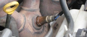
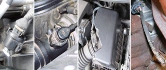
First of all, it is important to understand the operating principle of the sensor located between the thermostat and the block head. This element has two contacts leading to the fan and control unit. Its main function is to help regulate the fuel mixture, depending on the engine temperature. Thanks to it, all the main characteristics of the VAZ-2114 engine are adjusted.
DTOZH is considered one of the most reliable and rarely fails. If it produces the wrong temperature, the consequences may be:
- increased fuel consumption;
- problems with starting the engine, especially in winter (the computer does not read the engine temperature correctly);
- uneven operation of the power unit, detonation and loss of power;
- change in engine operating temperature (normally it fluctuates between 80 and 90 degrees);
- antifreeze boiling in the expansion tank;
- change in exhaust color due to a different composition of exhaust gases.
If the sensor malfunctions, the computer cannot correctly read the engine temperature, so it incorrectly sends signals to start the fan and fuel injection.
How to fix error 10?
Car service specialists check error 10 with an OBD-2 scanner. Since low voltage in the network is a consequence of weak battery charging, first check its charge level. Every self-respecting car owner is recommended to have a multimeter to monitor the condition of electrical wiring, leads, contact connections and the battery itself. Sometimes VAZ 2114 on-board computers provide erroneous information. This happens because the sensors going from the battery to the computer have “intermediaries” in which the voltage is lost. Therefore, to ensure that the readings are correct, the battery should be measured directly, preferably with a digital multimeter. It is more convenient to use and has less distortion than the traditional one. The voltage in the battery is measured first with the engine running. Normally, the readings should be 13.5-14 V. If it reads 14.2 V or higher, then the battery is discharged and the generator is overloaded to maintain the required voltage. If the multimeter shows a voltage of 13-13.4 V when the engine is running, it means that the battery is not fully charged, and therefore the generator is not working well. The alternator brush may be worn out and require replacement. Pictured: worn generator brushes. New brushes must protrude no less than 5 mm.
If the battery voltage shows less than 11 V when the engine is not running, then the battery is discharged, and before diagnosing the fuel sensor, it must be charged and make sure that the generator is working normally.
It should be taken into account that in cold weather the measuring device may show increased voltage in the vehicle's electrical network for the reason that the battery may have discharged a little overnight due to sub-zero temperatures, or the electronics have reacted to the lower air temperature and are putting more charge into the battery . There is nothing wrong with increased battery voltage. As soon as the electrical consumers turn on, the voltage will equalize.
In addition to the charging state, it is also necessary to inspect the terminals for the presence of oxidation. If necessary, they are cleaned. After making sure the condition of the battery, charging it if necessary, after checking the generator and its brushes, you should again reset all indicators by de-energizing the computer. If the error does not disappear or it changes to number 2, or 0460, you should proceed to checking the fuel level sensor circuit. For this you will also need a multimeter. During the check, it is necessary to inspect the contacts on the FLS itself, ring the wiring coming from it for a short circuit or break. It is also necessary to inspect the sensor itself. It is located next to the submersible fuel pump under the gas tank cap.
The Russian automaker VAZ produces a sufficient range of cars. Brand models are in great demand among domestic car enthusiasts and in the CIS countries. The popularity is due to the moderate cost and cheap repair of cars. However, problems happen with any vehicle and the plant’s products are no exception. Error codes for the VAZ 2114 injector can guide the motorist regarding the area of the breakdown and help in troubleshooting the problems.
Checking the generator and changing the brushes
Most often, brushes on a generator fail. They are replaced according to the instructions:
- Remove the negative terminal from the battery and unscrew the positive wire from the generator housing. Pull out the wire chip that transmits voltage to the winding.
- Now you need to release the latches and remove the casing from the generator. It is under it that the brush assembly is located.
- Unscrew the two screws and disconnect the wire leading to the brushes.
- Pull out the brush block and inspect it; if the surface is very worn, then you need to install a new similar part in its place.
Assembly of the unit is carried out in the reverse order. Before doing this, you need to check the condition of the anchor. If too much offset has formed on it at the point of contact with the brushes, then you need to remove this unit and grind it on a lathe. If you leave this point without attention, then very soon the new brushes will become unusable.
Diagnostics
There are two ways to set error codes for VAZ 2114 injector 8 valves. However, each method has unique advantages and disadvantages.
Self-diagnosis of VAZ 2114: error codes and their interpretation
The self-diagnosis method does not require the driver to have complex instruments or additional units. To complete the procedure, the car itself is enough.
The standard sequence of actions looks like this.
- Press the odometer reset button.
- Turn the ignition key to position No. 1 (turn on the on-board electrics).
- Release the mileage reset button. After this, the instrument arrows will make a full revolution and return to their place.
- Press the reset button a second time and release. The command displays the firmware version indicator.
- Repeat step No. 4 - this will display error codes on the on-board computer.
If the sequence of actions is performed correctly, all indicators will light up and the display will show a two-digit fault code.
Note!
A failure signal may be a lack of response from the indicator. In this case, it is necessary to check the circuit coming from the device.
The most common error codes for the VAZ 2114 panel, occurring in 90% of cases:
- 1 – microprocessor failure, flashing required;
- 2 – error code 2 VAZ 2114 indicates that there is an interruption or disruption in the wiring of the float sensor inside the gas tank;
- 4 – electrical wiring short circuit, voltage limit exceeded;
- 8 – error code 8 on the VAZ 2114 indicates a drop in voltage in the network, the battery may have run out;
- 12 – in the VAZ 2114, error code 12 indicates that the warning lamp is not functioning properly;
- 13 – open circuit of the oxygen sensor;
- 14 – error code 14 on the VAZ 2114 warns the driver that the engine has overheated or the antifreeze temperature sensor has shorted;
- 15 – short circuit or DTOZh has failed;
- 16 – exceeding the permissible voltage limit of the on-board network;
- 17 – BS voltage has dropped critically, battery discharge is allowed;
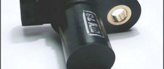
- 19 – DPKV does not respond or there is a short circuit on the line;
- 21-22 – incorrect response of the TPS, possible short circuit or wiring break;
- 23/25 – short circuit of the throttle position sensor;
- 24 – speedometer failure, power cords may be broken;
- 27/28 – CO sensor worn out or broken;
- 33/34 – problems with the mass air flow sensor, possible power loss or short circuit;
- 35 – IAC sensor has failed, can only be treated by complete replacement;
- 41 – incorrect phase distribution covered or shorted;
- 42 – the circuit has failed or the wires of the electronic ignition unit have been broken;
- 43 – mixture detonation sensor is faulty;
- 44/45 – there is a violation of the fuel supply to the engine, the system may trip, jerks appear during acceleration, and it picks up speed poorly;
- 51 – ROM is acting up;
- 52 – similar for RAM;
- 53 – potentiometer failure;
- 54 – break in wiring for octane corrector;
- 55 – excessive leanness of the mixture during acceleration;
- 61 – interruptions in the operation of the lambda probe.
In some cases, errors may be superimposed on each other if the failure is similar. For example, if errors 1 and 4 intersect, the panel will indicate "5".
It is important to know that after viewing, VAZ 2114/2115 error codes do not disappear on their own after repairs are performed. They need to be forced reset. To complete the work you will need a simple sequence of actions:
- turn on the car ignition;
- remove the terminals from the battery;
- wait 20-30 seconds;
- return the clamps to their place.
This also needs to be done if you are planning a trip to a service station. Having discovered the instructions from the on-board computer, the technicians will correct these problems, which will definitely be more expensive.
The disadvantages of an independent procedure include the low accuracy of the data. On-board diagnostics only show the general direction vector where the fault should be looked for.
Check using diagnostic equipment
You can identify error codes for VAZ 2115 and 2114 using a laptop with a special program. The tool is connected to the vehicle's test socket through a set of adapters. The wizard configures the software, and after diagnostics, one or more faults will be displayed on the computer screen in the form of a five-digit code.
The first part is the letter:
- B – damage to body panels;
- C – chassis or suspension malfunction;
- P – electrical, engine or transmission disorder;
- U – damage to the terminal for information exchange.
The second part is a single digit:
- 0 – typical indicator according to the SAE standard;
- 1/2 – conveyor failure code;
- 3 – reserve.
The next element is the breakdown group indicator:
- 1/2 – defect in the fuel/air line;
- 3 – ignition and related elements;
- 4 – catalyst;
- 5 – XO of the power plant;
- 6 – ECM and related wiring;
- 7/8 – transmission blocks.
The final two numbers point directly to the problem itself.
Incorrect data during self-diagnosis
According to reviews from experienced VAZ-2115 owners, the on-board computer on this model cannot be called ideal.
They recommend not relying entirely on self-diagnosis, since the data obtained with its help does not accurately indicate the problems of transport hubs. The self-diagnosis system is based on processing signals from conventional sensors. They cannot convey the specific data needed to identify the problem. Almost all components have flaws. Several controllers are located on the pneumatic system and on the fuel injection mechanism. They can fail either in the event of a serious breakdown or in the event of a wire break.
Most often, VAZ-2115 owners encounter incorrect operation of the generator. It is this unit that often supplies too low or high voltage, which leads to malfunction of all controllers.
Basic error codes for VAZ 2114 injector: decoding
Note!
The table is also relevant for version 2115.
Exhaust system – 0000
- 30 – open circuit of the oxygen sensor heater to the catalytic converter;
- 31 – also with a short circuit to the car body;
- 32 – similar with a short circuit to 12V;
- 36-38 – the same value as 30 only for the output sensor.
Air line defects – 0100
- 102/103 – Mass air flow sensor open circuit or signal violation;
- 112/113 – sensor lines t ˚ overboard, impulse violation;
- 116 – engine overheating;
- 117/118 – damage to the DTOZH circuit;
- 122/123 – TPS line, short circuit or insulation failure;
- 130 – failure of the oxygen sensor in front of the catalyst;
- 131/132 – similar element, signal level violation;
- 133 – slow response of DK1 to commands;
- 134 – break in the power cable DK1;
- 136 – DK2 is broken;
- 137/138 – short circuit or violation of wiring DK2;
- 140 – fuse DK2 burned out;
- 141 – the heater of the same device is broken or damaged;
- 171/172 – excessively lean or enriched fuel mixture.
Error codes VAZ 2114 1.6 liters related to fuel supply - 0200
- 201/204 – break in the injector control line for all injectors in series;
- 217 – motor overheating;
- 230 – the fuel pump has failed or the corresponding relay has burned out;
- 261/264/267/270 – short circuit of the injector control circuit at +12 V, respectively, for each insert;
- 263/266/269/272 – failure or defect of the injector driver for each in series;
- 262/265/268/271 – Short circuit of highways to the car body.
Error codes on the VAZ 2114 on-board computer indicating a breakdown in the ignition system - 0300
- 300 – there are misfires;
- 301-304 – similarly for each cylinder, respectively;
- 326-328 – DDS is broken or there is no signal;
- 335-338 – failure, short circuit or interruption of the DPKV wiring;
- 342/343/346 – malfunction of the phase distribution sensor;
- 351-354 – open circuit for all pistons in series;
- 363 – the mixture in the cylinders does not ignite, emergency fuel supply cut-off.
Additional attachment that does not have a direct effect on the motor – 0400
- 422 – the catalyst may have clogged or the exhaust gas flow rate has dropped critically;
- 441 – failure of power supply to the adsorber purge valve;
- 444 – power failure above the specified element;
- 445 – short circuit of the gearbox to the car body;
- 480 – power wires to the main radiator cooler are damaged;
- 481 – failure of the coolant fan control circuit No. 2.
Failure, malfunctions in the SU speed control system – 0500
- 500 – speedometer sensor is broken;
- 506/507 – low or high speed of the vehicle;
- 511 – XX regulator – lines from the relay and ECU are interrupted;
- 560 – the battery is low or the power cable is broken.
- 562/563 – Short circuit on on-board wiring.
On-board network of auxiliary or main equipment – 0600
- 601 – ECM, ROM error;
- 615 – secondary starter relay, wiring damage;
- 616/617 – also with short circuit to ground or 12V;
- 627 – fuel pump control relay, possible line break;
- 628/629 – similar with a short circuit to the body or on-board system;
- 645-647 – compressor clutch, damage to the wiring with contact with the housing or other cables;
- 650 – the “Check Engine” lamp is broken, check the engine, there may be damage to the wiring;
- 654 – tachometer failed;
- 685-687 – malfunction of the main engine control relay, complete replacement of the part is required;
- 691/692 – problems with the main cooling fan relay.
Auxiliary systems – 1000
- 102 – breakdown of heater DK1;
- 115 – failure or malfunction of the above device;
- 123/124 – violation, too rich/lean mixture at idle;
- 127/128 – similar, only for partial load on the internal combustion engine;
- 135 – rupture of heating line DK1;
- 136/137 – incorrect fuel supply at low engine load, the throttle drive may be malfunctioning;
- 140 – discrepancy between measured and actual load;
- 141 – failure of heater DK2;
- 171/172 – incorrect information comes from the potentiometer;
- 301-304 – the ignition in the cylinder does not work correctly, consistently for all combustion chambers;
- 386 – incorrect sequence of testing the detonation channel;
- 410/425/426 – wiring of the canister purge flap, short circuit or line damage;
- 500 – the fuel pump relay line is damaged;
- 501/502 – similarly with a short circuit to the body or wiring;
- 509/513/514 – control center of the XX regulator, open or short circuit on board or 12V;
- 541 – damage to the wire of the BN relay, possible oxidation of the terminal;
- 570 – break in immobilizer control cables;
- 602 – no power to the ECM, oxidation of the pads is allowed;
- 606 – the bump sensor is broken, the part needs to be replaced;
- 616/617 – similarly with a change in signal level, there may be a short circuit inside the device;
- 2301/2303/2305/2307 - the ignition coils are shorted to 12 volts, in series for each piston.
Important!
Only the most popular error codes for the dashboard of the VAZ 2114 and similar models are listed here. There are other indices, but due to their low prevalence they are not mentioned.
Instructions for performing diagnostics via a laptop with your own hands
For diagnostics you will need a laptop and a diagnostic adapter. The laptop can be of any power, for diagnostic purposes it does not matter. The adapter is universal and suitable for all VAZ models (video KV Autoservice).
There may be a mismatch between the diagnostic electrodes. In this case, you can buy an adapter. A diagnostic program is included with the adapter, but it can be downloaded on the Internet at specialized sites. They have the same set of functions, they may differ in unique characteristics.
When connecting a laptop, you must turn off the ignition.
One end of the adapter connects to the DR, and the other end directly to the laptop's USB port. After connecting the adapter, turn on the ignition. At the next stage, we launch the program and begin diagnostic work. When the program starts, the computer connects to the electronic control unit.
The interface will depend on the loaded program. These can be lists with indicators or graphs with values. Based on these readings, you can draw the first conclusions about the operation of the engine and the main systems of the car.
How to fix the problem
After diagnosis, the problem should be repaired. When reading a signal, it is necessary to check the circuit and devices following it. The most accurate method is to replace the damaged part with a known good one (new). This will eliminate the possibility of incorrect repairs. If the device is in working condition, the lines are checked; usually a primitive test is sufficient. However, if the control unit or relay fails, you will need a special tester and the ability to use it.
Separately, it is necessary to take into account that factory terminals and blocks become loose and oxidize over time. If the contact on the hitch deteriorates, the on-board computer or laptop program will say that the part is damaged, even if it is not.
You can prevent this from happening in the following way.
- Check the condition of the connectors once every 5000 km. The pads should sit in place tightly, without play. If necessary, elements must be replaced with new ones.
- Check plug connectors two to three times a year for oxidation. Oxides reduce the flow of electricity through on-board wiring, which leads to incorrect display of information.
- Experts recommend purchasing and using oil for electrical terminals. The liquid is similar in composition to transformer lubricants. The formula prevents water and oxygen from reaching metals, which prevents them from rusting.
Important!
You can diagnose VAZ 2114 error codes on the instrument panel and ECU yourself, only if you understand the essence of the process. If you don’t have confidence in your own abilities, it is recommended to contact a qualified technician.
If you have the appropriate knowledge and the necessary equipment, you can find and correctly decipher the error codes of the VAZ 2115 injector and other elements yourself. Due to the simplicity of the car's electrical circuit, the user does not require deep knowledge of mechanics or electronics.
Removing the error from the device memory
This procedure is used in three cases:
- the occurrence of an error blocks the ability to operate the car (you need to get to the service station under your own power);
- a complete check of all components was carried out and no fault was found;
- The damaged part has been repaired or replaced.
To reset the on-board control system data, you must remove all terminals from the battery and then plug it back into the vehicle's power circuit. It will only take a few seconds to disconnect the battery. After this, the error record will be erased from the system memory. If you want to carry out this procedure for further operation of the vehicle, then remember that the trip should be short - to the nearest car service center.
Car diagnostics
The appearance of a lit “Check Engine” lamp on the instrument cluster signals the driver that a problem has arisen in the vehicle’s electrical system. You need to understand that checking the vehicle yourself and at a service station can give different results. Special equipment available to professionals will allow more accurate detection of faults.
Self-diagnosis
On a VAZ 2115, the owner can do independent diagnostics and find out what errors are stored in the memory of the engine control unit. The procedure is carried out by calling up fault codes on the dashboard or using a diagnostic adapter.
To carry out diagnostics on the electronic instrument panel, you must perform a certain sequence of actions:
- Sit in the driver's seat of the car, insert the key into the ignition and press the daily mileage reset button located on the instrument cluster.
- Turn the lock key to the ignition switch position.
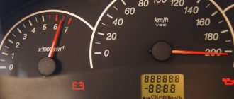
- Release the key, starting the self-diagnosis process. Visually, this will look like turning on the backlight, all signal lamps, possible symbols on the LCD screens and testing the instruments (the arrows will move across the entire scale in both directions).
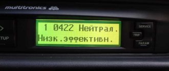
- Press the key again and release. The second press displays the software version of the instrument cluster on the screen located under the speedometer (inscription like Uer x. x).
- Press the key again, after which the errors in the memory will be displayed on the screen.
Instrument cluster VAZ 2115, the button is located on the right side of the speedometer
The driver can perform self-diagnosis on the electromechanical panel and the “January-4” control unit according to the following sequence:
- Turn off the ignition.
- Open the diagnostic connector cover located on the center console.
- Connect contact B to the negative terminal of the battery (to the body). Contact A, connected to the engine crankcase, is suitable for this.
- Turn on the ignition. The “Check Engine” lamp will flash code 12, which means the diagnosis has begun. The light signals are given as follows - a long flash, then a pause (about 2 seconds), two short flashes, a long pause (about 3 seconds). Signal 12 is sent three times. If there is no signal, the diagnostic system is inactive or faulty. After this, the Check Engine light will flash and list the errors in memory. Each code is repeated three times. If there are no errors in the memory, code 12 will continue to be transmitted.
Electromechanical instrument cluster
Diagnostic connector pinout
To read controller errors, a special K-Line adapter is used, which is connected to the diagnostic connector using a connector. This connector is located on the center console behind a plastic plug (below the cigarette lighter and ashtray). The adapter has a cord with a USB connector at the end that connects to any laptop. A special program for reading and resetting errors must be installed on the device (OpenDiagFree version 1.4 or 1.6).
The procedure for reading errors is quite simple, you need to:
- Check the level of process fluids.
- Open the connector cover and turn on the ignition.
- Connect the adapter or scanner to the diagnostic socket.
- Launch the software on the laptop.
- View available errors in the program dialog box.
- Decrypt the codes using the program interface or decryption table.
- Eliminate the causes of malfunctions and re-diagnostics.
Is it possible to reset the error on the monitor yourself?
You can delete the error code from the memory of the VAZ control unit by disconnecting the terminal from the battery.
The reset procedure is performed as follows:
- The vehicle's ignition system is activated, but the power unit does not start.
- The engine compartment of the vehicle opens. Using a wrench, loosen the screw that secures the terminal clamp on the negative output of the battery.
- After about one minute the contact is reconnected.
- The engine compartment of the car is closed, the ignition system in the car is turned off.
- The car engine is starting. If the “Check” indicator remains lit on the dashboard, it should disappear on its own after a few kilometers.
If the fault monitoring system malfunctions, then another question arises: how to get to the service station. Of course, you can resort to the services of a tow truck, but this will require additional funds. If you are 100% sure that your car is working properly, then you can simply remove the failure records from the computer’s memory. To do this you will need to take the following steps:
- Stop the engine if it has been running.
- Turn off the ignition.
- Remove the terminals from the battery.
- After a few seconds, turn the battery back on, that is, return the terminals back.
In most cases this helps. If it’s frosty outside and the car won’t start because the battery has cooled down too much, then after disconnecting it, you should bring the battery into a warm place. In this case, you will not be able to immediately use your VAZ-2115.
The listed actions will help clear the memory of the on-board computer even after the breakdown has been eliminated. After you replace the faulty part, you will need to first try to start the car, and then follow the instructions given above. As a rule, after repairs, auto mechanics immediately reset the memory of the monitoring system.
First of all, the owner of a VAZ-2115, having discovered that the control system has begun to malfunction, asks the question: how to take his car to the nearest service station? Of course, the most convenient way is to order a tow truck to the desired address by telephone, but the cost of such a service will not satisfy everyone.
You can independently deliver your “iron four-wheeled horse” to a service station if you eliminate messages about previously detected failures from the on-board computer’s memory. But this method can only be used if the car owner is completely confident in the serviceability of his car.
- If the engine is running, it must be turned off.
- The car's ignition is also turned off.
- The connecting terminals are removed from the battery.
- After 30-40 seconds, the terminals are reconnected to the battery.
As practice shows, the above actions almost always help to remove a failure record from computer memory, which, in turn, will help the car owner eliminate the cause of the malfunction on his own or take the car to a service station.
Meaning and decoding of codes
During self-diagnosis of a VAZ 2115 with an injector, only numbers or flashes that code the error will be shown on the instrument panel. When reading trouble codes from an electromechanical instrument cluster, it is necessary to record the number of flashes and calculate error numbers from them. Their purposes can be deciphered using a special list. Most of these faults can be resolved independently by replacing failed sensors.
Self-diagnosis codes
When performing diagnostics, it is necessary to take into account that the number on the screen may indicate two summed errors. For example, 9 indicates the presence of two faults - numbered 1 and 8.
| Numeric combination | Decoding |
| 1 | ECU problem |
| 2 | Incorrect data from the fuel level sensor |
| 4 or 8 | Network power problems |
| 12 | Malfunction of the error lamp circuit in the instrument cluster |
| 13 | No signal from lambda probe |
| 14 or 15 | Incorrect data from temperature sensor |
| 16 or 17 | Problems with the network power supply, it is necessary to check for short circuits |
| 19 | Motor shaft position sensor error |
| 21 or 22 | Throttle sensor error |
| 23 or 25 | Incorrect operation of the intake air temperature sensor |
| 24 | Speed sensor faulty |
| 27 or 28 | No signal from lambda probe |
| 33 or 34 | No air flow data available |
| 35 | Idle speed control sensor is faulty |
| 42 | Ignition control circuit problem |
| 43 | Knock sensor failure |
| 44 or 45 | Violation of the composition of the mixture |
| 51 or 52 | ECU memory errors |
| 53 | Error in CO setting sensor (installed on cars without converter) |
| 54 | Octane corrector sensor (installed on cars without a converter) |
| 55 | Violation of the composition of the mixture |
| 61 | Failure of the lambda probe |
An example of error 14 appearing on the panel
Table of decoding codes for flashes calculated during diagnostics.
| Error code | Flash combination | Decoding |
| 12 | Long-pause-two short | Diagnostic circuit malfunction |
| 14 | Long-pause-four short | Engine temperature sensor malfunction |
| 15 | Long-pause-five short | Likewise |
| 16 | Long-pause-six short | Abnormally high mains voltage |
| 17 | Long-pause-seven short | Abnormally low mains voltage |
| 19 | Long-pause-nine short | Crankshaft position sensor failure |
| 21 | Two long, pause, one short | Incorrect data from the throttle position sensor |
| 22 | Two long, pause, two short | Likewise |
| 24 | Two long, pause, four short | Problem with the speed sensor |
| 27 | Two long, pause, seven short | Lambda probe failure |
| 28 | Two long, pause, eight short | Likewise |
| 33 | Three long, pause, three short | Air flow meter needs to be checked |
| 34 | Three long, pause, four short | Likewise |
| 35 | Three long, pause, five short | Idle speed outside the tolerance range |
| 43 | Four long, pause, three short | No signal from knock sensor |
| 51 | Five long, pause, one short | Memory error in block |
| 52 | Five long, pause, two short | Error in controller |
| 53 | Five long, pause, three short | Memory error in block |
| 61 | Six long-pause-one short | No signal from the immobilizer |
The data obtained allows you to quickly find the faulty element and eliminate the cause of the error.
The video from the Garage channel shows diagnostics on a VAZ 2115 using a scanner and laptop.
Controller errors
The most common controller errors encountered during diagnostics are listed in the table.
| Program error number | Decoding |
| R 0030-0038, 0141 | Malfunction of the lambda probe heating system |
| R 0102 and 0103 | Incorrect signal from the air supply sensor |
| R 0112 and 0113 | Error in data from intake air temperature sensor |
| R 0115-0118 and 0217 | Problems detecting engine temperature or overheating |
| R 2122 and 2123, 0222 and 0223, and 2138 | Incorrect signal from the gas pedal and throttle position sensor |
| R 0171-0172 | Incorrect mixture parameters |
| R 0201-0204 | Faulty injectors (each cylinder has its own code) |
| R 0261-0272 | Problems with injector control |
| R 0130-0134 | Problems with the functioning of the lambda probe before the converter |
| R 0136-0140 | Problems with the functioning of the lambda probe after the converter |
| R 0300 | Multiple misfires |
| R 0301-0304 | Cylinder misfires |
| R 0326-0328 | Knock sensor failure |
| R 0351-0352, 2301 and 2304 | Monitoring the operation of ignition coils |
| R 0422 | Failure of the neutralizer |
| R 0691-0692 and 0693-0694 | Failure of the first and second cooling fan start relays |
| R 0560-0563 | Problems with power supply |
| R 0627-0629 | Indicates incorrect operation of the fuel pump control circuit |
| R 1602 | Malfunction in the engine parameters control controller |
Reset errors
After self-diagnosis, finding out the cause of the problem and correcting the breakdown, the errors can be reset.
To do this, go to the error viewing menu, press the odometer reset key and wait a few seconds. The number 0 will light up on the screen - the error has been reset. In this case, data about problems is stored in the unit’s memory and must be deleted. If left, the “Check Engine” light will light up in the instrument cluster. In addition, self-diagnosis may not read all electrical system errors; the error removal procedure will show whether a more detailed analysis of the vehicle’s electronics is needed.
To reset the error, do the following:
- Turn on the ignition.
- Open the hood and remove the negative terminal from the battery. Wait about a minute, connect the wire back and close the hood.
- Turn off the ignition.
- Turn on the ignition again and start the engine. The Check Engine light may come on briefly and then go off.
If the symbol remains illuminated, there is an ongoing problem with some sensor or wiring in the vehicle. It can only be found out using a special scanner. It is necessary to conduct additional diagnostics to determine the problem node. Then carry out repairs and clear any existing errors using a computer diagnostic program for the ECU.
Resetting errors on cars with an electromechanical instrument cluster is carried out by disconnecting the negative terminal of the battery from the on-board network for 10 seconds. The ignition must be turned off.
How to decipher codes
If you do not know what the data displayed on the display means, then it is pointless to independently check the functionality of the sensors. Therefore, it is important to know how to decipher combinations. The following numbers appear most frequently:
- If code 1 appears, then the fault lies in the microprocessor of the on-board unit itself. This error can be corrected by changing the computer software. It is important to use only official firmware, otherwise you will damage the entire electrical system of the car.
- If the malfunction is hidden in the incorrect operation of the fuel sensor, then 2 will appear on the display. The same number means problems with the electrical wiring, especially if it is displayed in addition to 8.
- When the voltage in the network is high, error 4 appears, and when voltage is low, error 8 appears. If you notice these data, then you need to check the generator and battery. VAZ-2115 owners most often encounter generator malfunctions. It will need to be repaired or completely replaced.
- Malfunctions in the operation of the control lamp in the diagnostic circuit are displayed on the display in the form of a combination - 12.
- Failure of the oxygen level sensor is displayed as error 13. Check the filters, most often they are the cause of this combination. Combinations 33 and 34 indicate mass air flow. In this case, you may need to replace the sensor itself. A malfunction of the controller itself is indicated by code 61 displayed on the display. Experts recommend that if one of these combinations occurs, a full check of the functionality of the vehicle components is carried out. Start with the electrical wiring.
- Car enthusiasts often encounter combinations 14 and 15, which may appear along with an indicator indicating the need to add antifreeze. It is important to interpret this malfunction correctly - the appearance of this data on the display means that the temperature in the system is increased or decreased. The reason for this may be a malfunction of the thermostat. If the node is not damaged, then the problem most likely lies in the control unit.
- Combinations 16 and 17 are output when the voltage in the on-board network is insufficient or too high. It is necessary to check all wiring for short circuits and breaks.
- Code 19 occurs if the crankshaft position sensor does not respond correctly to the test. In this case, it is necessary to check the vehicle with an external device. If it shows a combination in the range from P0340 to P0343, then the breakdown may be hidden in the controller itself.
- With error 24, the on-board computer stopped receiving data about the vehicle speed.
We recommend: Poor car starting when cold - reasons and solutions
Connecting the diagnostic connector to the unit
Troubleshooters for elm 327 can be downloaded from the Internet, many of which are free versions. Now your VAZ is ready to detect errors in various vehicle systems and you can always download error codes from us.
Currently, most car manufacturers install injection engines in their cars. And if you own a car with a fuel injection system that uses injectors, then you need to at least know the principle of operation of the injector in order to detect this or that malfunction in time.
Therefore, the processes in this mechanism are as follows. The high pressure air flow is analyzed by a special electronic sensor, which measures a certain volume of air masses. Data from the sensor enters a computer unit, which also analyzes other data, for example, air temperature, engine. After processing all the information received, the computer determines the size of the fuel mixture required for the resulting volume of air in order to obtain maximum efficiency from the engine output.
By the way, they increase engine efficiency. Injector diagnostics are usually carried out after engine malfunctions or when purchasing a used car. A special device for diagnosing the engine management system, the functions of which can be performed by a regular on-board computer with the ability to diagnose engine problems.
A compressor that can measure compression in engine cylinders. This device helps detect holes in the cylinder head gasket, valves, etc. A pressure gauge is a device that can be used to measure the level of fuel pressure and thereby diagnose a malfunction of the pressure regulator, fuel pump, or clogged fuel filters.
Diagnostic tool interface
When a list of detected errors is displayed, their explanation can be found in the test file that is usually included with the program. Decipher all errors that may occur in the event of a malfunction.
After deciphering the detected error codes, you should begin to eliminate them. First of all, it is worth checking the sensors, since the correctness of the readings and the operation of the ECU depend on their functionality. A faulty sensor may be causing the error message. For a more accurate diagnosis, additional checks of machine components may be required. Once you have fixed all the problems, be sure to run a test to make sure everything is working without errors.
Don't forget that all data is stored in the microcontroller's memory. Therefore, before a new scan, they must be reset.
To do this, turn off the ignition and turn off the diagnostic equipment. To reset the microcontroller, simply disconnect the negative battery terminal. Then the process is repeated - the laptop is connected and diagnostics are repeated. The process is repeated until all errors are eliminated.