02/04/2022 11,050 VAZ
Author: Ivan Baranov
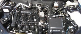
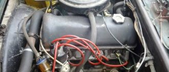
Optimal operation of a car engine depends on many parameters and devices. To ensure normal operation, VAZ engines are equipped with various sensors designed to perform different functions. What you need to know about diagnosing and replacing controllers and what are the parameters of sensors for VAZ injection engines is presented in the table in this article.
[Hide]
Typical operating parameters of VAZ injection engines
Checking VAZ sensors is usually carried out when certain problems are detected in the operation of the controllers. For diagnostics, it is advisable to know what malfunctions of VAZ sensors can occur; this will allow you to quickly and correctly check the device and replace it in a timely manner. So, how to check the main VAZ sensors and how to replace them after that - read below.
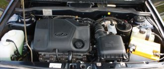
Basic parameters of controllers on VAZ injection engines
How to diagnose the error?
It is important to know
There are two options for diagnosing a VAZ car - testing using the instrument panel and using a computer. The second option is considered more accurate, but its implementation will require a special program and a cable for connecting to the diagnostic connector.
Checking using a computer is done like this:
- The diagnostic wire is connected to the laptop. Its second end must be connected to the OBD2 connector in the Lada car. The location of this block differs depending on the car model; this nuance must be clarified in the service manual.
- A diagnostic program is launched on the computer, which allows you to decipher error codes. To start the test, press the corresponding button.
- The diagnostic process begins. Depending on the utility, the program can separately check the operation of the engine, transmission or electronics.
- After the test is completed, combinations of faults will appear on the computer screen that need to be deciphered. Depending on the program, a description of the error may also be displayed immediately.
Diagnostics using the dashboard is performed as follows:
- The car owner sits in the driver's seat and presses the daily mileage reset button on the odometer.
- The key is inserted into the lock and scrolled to the “ACC” position.
- The daily mileage reset button is released. The arrows on the speedometer, tachometer, and sensors will begin to quickly move from the minimum position to the maximum.
- The odometer key is pressed and released. An inscription with the software version will be displayed on the instrument cluster screen.
- After the third press of the odometer key, combinations of faults will appear on the screen.
Video: diagnosing a VAZ using the dashboard
The CarFance channel in its video showed in detail the process of testing a Lada car using a control combination.
Features, diagnostics and replacement of elements of injection systems on VAZ cars
Below we will look at the main controllers!
Hall
There are several options for how you can check the Hall sensor of a VAZ:
- Use a known working device for diagnostics and install it instead of the standard one. If after replacement the problems in engine operation cease, this indicates a malfunction of the regulator.
- Using a tester, diagnose the controller voltage at its terminals. During normal operation of the device, the voltage should be from 0.4 to 11 volts.
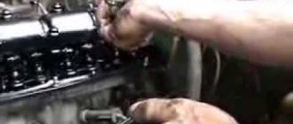
The replacement procedure is performed as follows (the process is described using the example of model 2107):
- First, the switchgear is dismantled and its cover is unscrewed.
- Then the slider is dismantled; to do this, you need to pull it up a little.
- Remove the cover and unscrew the bolt that secures the plug.
- You will also need to unscrew the bolts that secure the controller plate. After this, the screws that secure the vacuum corrector are unscrewed.
- Next, the retaining ring is dismantled and the rod is removed along with the corrector itself.
- To disconnect the wires, you will need to move the clamps apart.
- The support plate is pulled out, after which several bolts are unscrewed and the manufacturer dismantles the controller. A new controller is being installed, assembly is carried out in the reverse order (the author of the video is Andrey Gryaznov).
Speeds
The following symptoms may indicate a failure of this regulator:
- at idle, the speed of the power unit floats, if the driver does not press on the gas, this can lead to an arbitrary shutdown of the engine;
- the speedometer needle readings float, the device may not work as a whole;
- fuel consumption has increased;
- the power of the power unit has decreased.
The controller itself is located on the gearbox. To replace it, you only need to jack up the wheel, disconnect the power wires and remove the regulator.
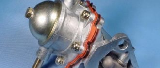
Fuel level
The VAZ or FLS fuel level sensor is used to indicate the remaining volume of gasoline in the fuel tank. Moreover, the fuel level sensor itself is installed in the same housing with the fuel pump. If it malfunctions, the readings on the dashboard may be inaccurate.
The replacement is done like this (using the example of model 2110):
- The battery is disconnected and the rear seat of the car is removed. Using a Phillips screwdriver, unscrew the bolts that secure the fuel pump hatch and remove the cover.
- After this, all wires leading to it are disconnected from the connector. It is also necessary to disconnect all the pipes that are supplied to the fuel pump.
- Then the nuts securing the clamping ring are unscrewed. If the nuts are rusty, treat them with WD-40 before unscrewing.
- Having done this, unscrew the bolts that directly secure the fuel level sensor itself. The guides are pulled out from the pump casing, and the fasteners need to be bent with a screwdriver.
- At the final stage, the cover is dismantled, after which you will be able to gain access to the FLS. The controller is replaced, the pump and other elements are assembled in the reverse order of removal.
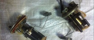
Photo gallery “Changing the FLS with your own hands”
1. To replace the FLS, remove the rear seat.
2. All connectors must be disconnected from the cover.
3. Disassemble the fuel pump and remove the device.
Idle move
If the idle speed sensor on a VAZ fails, this is fraught with the following problems:
- floating speed, in particular, when additional voltage consumers are turned on - optics, heater, audio system, etc.;
- the engine will start to stall;
- when the central gear is activated, the engine may stall;
- in some cases, failure of the IAC can lead to body vibrations;
- the appearance of a Check indicator on the dashboard, but it does not light up in all cases.
To solve the problem of device inoperability, the VAZ idle speed sensor can either be cleaned or replaced. The device itself is located opposite the cable that goes to the gas pedal, in particular, on the throttle valve.
The VAZ idle speed sensor is fixed using several bolts:
- To replace, first turn off the ignition and the battery.
- Then you need to remove the connector; to do this, disconnect the wires connected to it.
- Next, use a screwdriver to unscrew the bolts and remove the IAC. If the controller is glued, then you will need to dismantle the throttle assembly and disconnect the device, but act carefully (the author of the video is the Ovsiuk channel).
Crankshaft
The VAZ crankshaft sensor is used to synchronize the operation of the fuel supply and ignition systems. Diagnosis of DPKV can be made in several ways.
How to check the crankshaft sensor:
- To perform the first method, you will need an ohmmeter; in this case, the resistance on the winding should vary around 550-750 Ohms. If the indicators obtained during the test differ slightly, this is not a problem; the DPKV needs to be changed if the deviations are significant.
- To perform the second diagnostic method, you will need a voltmeter, a transformer device, and an inductance meter. The resistance measurement procedure in this case should be carried out at room temperature. When measuring inductance, the optimal parameters should be from 200 to 4000 millihenry. Using a megohmmeter, the power supply resistance of the device winding is measured at 500 volts. If the DPKV is working properly, then the obtained values should be no more than 20 MΩ.
To replace the DPKV, do the following:
- First, turn off the ignition and remove the device connector.
- Next, using a 10mm wrench, you will need to unscrew the analyzer clamps and dismantle the regulator itself.
- After this, a working device is installed.
- If the regulator changes, then you will need to repeat its original position (the author of the video about replacing the DPKV is the channel In Sandro's Garage).
Lambda probe
The VAZ lambda probe is a device whose purpose is to determine the volume of oxygen present in the exhaust gases. This data allows the control unit to correctly create the proportions of air and fuel to form a combustible mixture. The device itself is located on the exhaust pipe of the muffler, at the bottom.
The regulator is replaced as follows:
- First disconnect the battery.
- After this, find the contact of the harness with the wiring; this circuit comes from the lambda probe and connects to the block. The plug must be disconnected.
- When the second contact is disconnected, go to the first, located in the exhaust pipe. Using an appropriately sized wrench, unscrew the nut securing the regulator.
- Remove the lambda probe and replace it with a new one.
Loading …
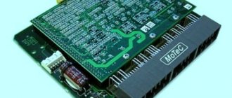
Types of ECU (esud, controller). What kind of ECUs are installed on VAZ?
"January-4", "GM-09"
The very first controllers on SAMARA were January-4, GM - 09. They were installed on the first models before the year 2000. These models were produced both with and without a resonant knock sensor.
The table contains two columns: 1st column – ECU number, second column – brand of “brains”, firmware version, toxicity standard, distinctive features.
VAZ 2113-2115 from 2003 are equipped with the following types of ECUs:
"January 5.1.x"
Interchangeable with “VS (Itelma) 5.1”, “Bosch M1.5.4”
"Bosch M1.5.4"
The following types of hardware implementation are distinguished:
"Bosch MP7.0"
As a rule, this type of controller is released onto the market and installed at the factory in a single volume. Has a standard 55-pin connector. Capable of working with recrossing on other types of ECM.
"Bosch M7.9.7"
These brains began to be part of the car at the end of 2003. This controller has its own connector, which is incompatible with connectors produced before this model. This type of ECU is installed on VAZ with EURO-2 and EURO-3 toxicity standards. This ECM is lighter weight and smaller in size than previous models. There is also a more reliable connector with increased reliability. They include a switch, which will generally increase the reliability of the controller.
This ECU is in no way compatible with previous controllers.
"VS 5.1"
The following types of hardware implementation are distinguished:
"January 7.2."
This type of ECU is made with a different type of wiring (81 pins) and is similar to Boshevsky 7.9.7+. This type of ECU is produced both by Itelma and Avtel. Interchangeable with Bosch M.7.9.7. As for the software, 7.2 is a continuation of January 5th.
This table shows variations of the BOSCH ECU, 7.9.7, January 7.2, Itelma, installed exclusively on the VAZ 2109-2115 with a 1.5L 8kL engine.
| 2111-1411020-80 | BOSCH, 7.9.7, E-2, 1.5 l, 1st ser. version |
| 2111-1411020-80h | BOSCH, 7.9.7, E-2, 1.5 l, tuning version |
| 2111-1411020-80 | BOSCH,7.9.7+, E-2, 1.5 l |
| 2111-1411020-80 | BOSCH,7.9.7+, E-2, 1.5 l |
| 2111-1411020-30 | BOSCH,7.9.7, E-3, 1.5 l, 1-gray. version |
| 2111-1411020-81 | January 7.2, E-2, 1.5 l, 1st version, unsuccessful, replace A203EL36 |
| 2111-1411020-81 | January 7.2, E-2, 1.5 l, 2nd version, unsuccessful, replace A203EL36 |
| 2111-1411020-81 | January 7.2, E-2, 1.5 l, 3rd version |
| 2111-1411020-82 | Itelma, dk, E-2, 1.5 l, 1st version |
| 2111-1411020-82 | Itelma, dk, E-2, 1.5 l, 2nd version |
| 2111-1411020-82 | Itelma, dk, E-2, 1.5 l, 3rd version |
| 2111-1411020-80 h | BOSCH, 7.9.7, without DC, E-2, din, 1.5 l |
| 2111-1411020-81 h | January 7.2, without dc, with, 1.5 l |
| 2111-1411020-82 h | Itelma, without dc, with, 1.5 l |
Below is a table with the same ECUs, but for 1.6l 8kl engines.
| 21114-1411020-30 | BOSCH, 7.9.7, E-2, 1.6 l, 1st gray, (buggy software). |
| 21114-1411020-30 | BOSCH, 7.9.7, E-2, 1.6 l, 2nd gray |
| 21114-1411020-30 | BOSCH, 7.9.7+, E-2, 1.6 l, 1st gray |
| 21114-1411020-30 | BOSCH, 7.9.7+, E-2, 1.6 l, 2nd gray |
| 21114-1411020-20 | BOSCH, 7.9.7+, E-3, 1.6 l, 1st gray |
| 21114-1411020-10 | BOSCH, 7.9.7, E-3, 1.6 l, 1st gray |
| 21114-1411020-40 | BOSCH, 7.9.7, E-4, 1.6 l |
| 21114-1411020-31 | January 7.2, E-2, 1.6 l, 1st series - unsuccessful |
| 21114-1411020-31 | January 7.2, E-2, 1.6 l, 2nd series |
| 21114-1411020-31 | January 7.2, E-2, 1.6 l, 3rd series |
| 21114-1411020-31 | January 7.2+, E-2, 1.6 l, 1st series, new hardware version |
| 21114-1411020-32 | Itelma 7.2, E-2, 1.6 l, 1st series |
| 21114-1411020-32 | Itelma 7.2, E-2, 1.6 l, 2nd series |
| 21114-1411020-32 | Itelma 7.2, E-2, 1.6 l, 3rd series |
| 21114-1411020-32 | Itelma 7.2+, E-2, 1.6 l, 1st series, new hardware version |
| 21114-1411020-30 h | BOSCH, dk, E-2, din, 1.6 l |
| 21114-1411020-31 h | January 7.2, without dc, with, 1.6 l |
"January 5.1"
All types of controllers of their type are built on the same platform and most often have differences in the switching of injectors and the DC heater.
Let's look at the following example of ECU firmware January 5.1: 2112-1411020-41 and 2111-1411020-61. The first version has phased injection and an oxygen sensor, the second version differs only in that it has parallel injection. Conclusion - the difference between the ECU data is only in the firmware, so they can be interchanged.
Wrong name – January 7.3. This is the last type of controller that is currently installed at AvtoVAZ. This type of ECU has been installed since 2007. on a VAZ with EURO-3 toxicity standard.
The manufacturers of this ECU are two Russian companies: Itelma and Avtel. Below, the table shows ECUs for engines with EURO-3 and Euro-4 toxicity standards.
Meaning and decoding of codes
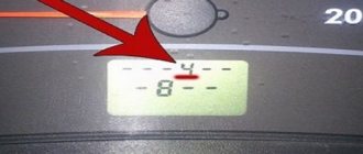
During self-diagnosis of a VAZ 2115 with an injector, only numbers or flashes that code the error will be shown on the instrument panel. When reading trouble codes from an electromechanical instrument cluster, it is necessary to record the number of flashes and calculate error numbers from them. Their purposes can be deciphered using a special list. Most of these faults can be resolved independently by replacing failed sensors.
Self-diagnosis codes
When performing diagnostics, it is necessary to take into account that the number on the screen may indicate two summed errors. For example, 9 indicates the presence of two faults - numbered 1 and 8.
| Numeric combination | Decoding |
| 1 | ECU problem |
| 2 | Incorrect data from the fuel level sensor |
| 4 or 8 | Network power problems |
| 12 | Malfunction of the error lamp circuit in the instrument cluster |
| 13 | No signal from lambda probe |
| 14 or 15 | Incorrect data from temperature sensor |
| 16 or 17 | Problems with the network power supply, it is necessary to check for short circuits |
| 19 | Motor shaft position sensor error |
| 21 or 22 | Throttle sensor error |
| 23 or 25 | Incorrect operation of the intake air temperature sensor |
| 24 | Speed sensor faulty |
| 27 or 28 | No signal from lambda probe |
| 33 or 34 | No air flow data available |
| 35 | Idle speed control sensor is faulty |
| 42 | Ignition control circuit problem |
| 43 | Knock sensor failure |
| 44 or 45 | Violation of the composition of the mixture |
| 51 or 52 | ECU memory errors |
| 53 | Error in CO setting sensor (installed on cars without converter) |
| 54 | Octane corrector sensor (installed on cars without a converter) |
| 55 | Violation of the composition of the mixture |
| 61 | Failure of the lambda probe |
An example of error 14 appearing on the panel
Table of decoding codes for flashes calculated during diagnostics.
| Error code | Flash combination | Decoding |
| 12 | Long-pause-two short | Diagnostic circuit malfunction |
| 14 | Long-pause-four short | Engine temperature sensor malfunction |
| 15 | Long-pause-five short | Likewise |
| 16 | Long-pause-six short | Abnormally high mains voltage |
| 17 | Long-pause-seven short | Abnormally low mains voltage |
| 19 | Long-pause-nine short | Crankshaft position sensor failure |
| 21 | Two long, pause, one short | Incorrect data from the throttle position sensor |
| 22 | Two long, pause, two short | Likewise |
| 24 | Two long, pause, four short | Problem with the speed sensor |
| 27 | Two long, pause, seven short | Lambda probe failure |
| 28 | Two long, pause, eight short | Likewise |
| 33 | Three long, pause, three short | Air flow meter needs to be checked |
| 34 | Three long, pause, four short | Likewise |
| 35 | Three long, pause, five short | Idle speed outside the tolerance range |
| 43 | Four long, pause, three short | No signal from knock sensor |
| 51 | Five long, pause, one short | Memory error in block |
| 52 | Five long, pause, two short | Error in controller |
| 53 | Five long, pause, three short | Memory error in block |
| 61 | Six long-pause-one short | No signal from the immobilizer |
The data obtained allows you to quickly find the faulty element and eliminate the cause of the error.
The video from the Garage channel shows diagnostics on a VAZ 2115 using a scanner and laptop.
Controller errors
The most common controller errors encountered during diagnostics are listed in the table.
| Program error number | Decoding |
| R 0030-0038, 0141 | Malfunction of the lambda probe heating system |
| R 0102 and 0103 | Incorrect signal from the air supply sensor |
| R 0112 and 0113 | Error in data from intake air temperature sensor |
| R 0115-0118 and 0217 | Problems detecting engine temperature or overheating |
| R 2122 and 2123, 0222 and 0223, and 2138 | Incorrect signal from the gas pedal and throttle position sensor |
| R 0171-0172 | Incorrect mixture parameters |
| R 0201-0204 | Faulty injectors (each cylinder has its own code) |
| R 0261-0272 | Problems with injector control |
| R 0130-0134 | Problems with the functioning of the lambda probe before the converter |
| R 0136-0140 | Problems with the functioning of the lambda probe after the converter |
| R 0300 | Multiple misfires |
| R 0301-0304 | Cylinder misfires |
| R 0326-0328 | Knock sensor failure |
| R 0351-0352, 2301 and 2304 | Monitoring the operation of ignition coils |
| R 0422 | Failure of the neutralizer |
| R 0691-0692 and 0693-0694 | Failure of the first and second cooling fan start relays |
| R 0560-0563 | Problems with power supply |
| R 0627-0629 | Indicates incorrect operation of the fuel pump control circuit |
| R 1602 | Malfunction in the engine parameters control controller |
Reset errors
After self-diagnosis, finding out the cause of the problem and correcting the breakdown, the errors can be reset.
To do this, go to the error viewing menu, press the odometer reset key and wait a few seconds. The number 0 will light up on the screen - the error has been reset. In this case, data about problems is stored in the unit’s memory and must be deleted. If left, the “Check Engine” light will light up in the instrument cluster. In addition, self-diagnosis may not read all electrical system errors; the error removal procedure will show whether a more detailed analysis of the vehicle’s electronics is needed.
To reset the error, do the following:
- Turn on the ignition.
- Open the hood and remove the negative terminal from the battery. Wait about a minute, connect the wire back and close the hood.
- Turn off the ignition.
- Turn on the ignition again and start the engine. The Check Engine light may come on briefly and then go off.
If the symbol remains illuminated, there is an ongoing problem with some sensor or wiring in the vehicle. It can only be found out using a special scanner. It is necessary to conduct additional diagnostics to determine the problem node. Then carry out repairs and clear any existing errors using a computer diagnostic program for the ECU.
Resetting errors on cars with an electromechanical instrument cluster is carried out by disconnecting the negative terminal of the battery from the on-board network for 10 seconds. The ignition must be turned off.