02/04/2022 6,800 VAZ 2106
Author: Ivan Baranov
All owners of domestic cars face the need to adjust the ignition. Especially when it comes to older vehicles. This material will help you learn how to adjust the distributor of a VAZ 2106 car and in what cases this may be required.
[Hide]
Components of the ignition system of the VAZ 2106
Previously, a distributor of the R-125B brand was installed on the car. This unit was mounted on the machine together with a carburetor marked 2103. The distributor had a special mechanical corrector in its design, and there was no vacuum regulator. The VAZ 2106 is equipped with spark plugs of type A17DV or plugs that have similar technical characteristics.
The design of the automotive system uses a VK347 type lock, equipped with an anti-theft device. The car uses a B117-A type ignition coil, which has an open magnetic circuit and is oil-filled and sealed.
The VAZ 2106 ignition is contact-based, but it is worth noting that sometimes there is also a contactless version of the system. The contact system is considered simpler in its design. VAZ contact ignition requires regular maintenance and monitoring of the condition of the contacts.
List of specialized tools and symptoms of malfunction
It is possible to install the ignition on a VAZ 2106 yourself using the following tools:
- open-end wrench with a diameter of 13 mm;
- a specialized wrench for removing spark plugs;
- voltmeter or 12 volt test light;
- car strobe light.
A characteristic symptom that on a VAZ 2106 it is necessary to install the ignition according to the marks on the crankshaft pulley is a sharp detonation of the engine and loss of power. The problems are obvious when driving at forty kilometers per hour (in 3rd gear) and suddenly trying to increase the speed with the gas pedal. The manifestation of such a malfunction, as well as an extraneous metallic sound from the engine during a sharp throttle change, will indicate the need to adjust the ignition angle, and any car owner can carry out this repair with his own hands.
Ignition coil and other elements
It is somewhat different in the contactless system from the one used in the classical one. The reason is the different value of the secondary voltage. Thus, when operating an internal combustion engine with a contact (including contact-transistor) ignition system, 25-30 thousand volts are required to form a spark gap. But in a non-contact system you need to generate over 30 kV, sometimes even up to 40 kV. Therefore, more turns are needed in the secondary winding.
The remaining elements are completely similar for all three designs discussed above. You choose the armored wires connecting all high-voltage circuits yourself. They can be either in a silicone or rubber shell. Contactless ignition 2107 can work with any high-voltage wires recommended by the manufacturer. Candles must be used those recommended by the manufacturer. In this case, you can again choose the brand yourself.
What is BSZ and how does it work?
To successfully install and configure contactless ignition, it is advisable to understand the operating principle of the system, which consists of the following elements:
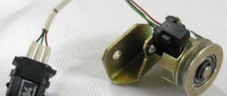
- Main ignition distributor (otherwise known as distributor). Inside it is installed a photoelectric Hall sensor, a vacuum drive for adjusting the advance angle and a so-called slider with a moving contact.
- A coil that produces a high voltage pulse. It has 2 windings: a primary winding, consisting of a small number of turns of thick wire, and a secondary winding, wound with a thin wire with a large number of turns.
- The electronic unit is a switch equipped with an aluminum cooling radiator. The latter plays the role of a fastening element.
- Spark plugs connected by high-voltage wires to the distributor.
- Wires for connecting elements to each other.
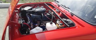
This is what the ignition system of a classic Zhiguli looks like
For reference. In the standard outdated VAZ 2106 systems, there was a contact group inside the distributor instead of a Hall sensor, and there was no switch at all.
The first contact of the coil is connected through the ignition switch relay to the generator, and the second to the control unit. Also, a high-voltage wire with a large cross-section goes from it to the distributor. There are 2 bundles of wires coming out of the distributor, connecting it to the switch and spark plugs. The system operates according to the following algorithm:
- After turning on the ignition by turning the key in the lock, a voltage of 12 V is applied to the primary winding of the coil, which creates an electromagnetic field.
- When the crankshaft rotates and one of the pistons reaches top dead center (TDC), the photoelectric sensor sends a signal to the switch, which briefly breaks the connection between the coil and the voltage source - the generator or battery.
- During a circuit break, a voltage pulse of 20 to 24 kV is generated in the secondary winding of the coil, transmitted through a large cross-section wire to the distributor slider.
- The movable contact of the slider directs the impulse to the spark plug where the piston reached TDC. A powerful spark jumps between its contacts, igniting the mixture of fuel and air in the combustion chamber.
- The distributor shaft is driven by a gear transmission connected to the crankshaft. When the next piston moves to TDC, the shaft rotates and the moving contact connects to another spark plug, and the Hall sensor sends the next signal and the sparking cycle is repeated.
Reference. In older systems, the circuit was broken mechanically using a cam on the distributor shaft, pressing on the contact group.
What benefits can you get?
But you will get many benefits if you install an electronic ignition on the VAZ-2106 instead of a contact one. It’s better to start with the fact that any driver likes to drive more than to repair the car. But frequent replacement of the contact group or its cleaning and adjustment causes terrible hostility among motorists. Moreover, the contact can fail at any time, so you need to have a spare one with you. But the electronic system on this side is much more reliable and does not require frequent maintenance.
But the most important thing happens in the engine - the very heart of any car. His work is returning to normal. It begins to function correctly, regardless of the rotation speed. Whether at idle or at 4000 rpm, the engine runs perfectly smoothly, stably, and the air-fuel mixture ignites in a timely manner. And this improves your comfort, increases engine reliability, and most importantly, increases its service life.
How to adjust the position of the distributor
If detonation is heard slightly or is absent altogether, then you should turn the distributor. So you need to adjust the ignition until the process settles down to one and a half seconds.
It is worth telling several possible situations of development of events when carrying out this procedure.
So, the ignition order of the VAZ 2106 is as follows:
- When detonation is very fast, that is, disappears after a few seconds, this indicates a normally performed adjustment. If it is after five seconds, then there is no need to make any adjustments.
- Prolonged detonation. To slow down this process, you need to stop and loosen the distributor body, and turn it one compartment forward. Continue these steps until the process continues for the desired period of time.
- No detonation occurs. This is not the correct “symptom”. In this situation, you need to turn the distributor towards minus.
Removal and installation of the ignition distributor of the VAZ 2106 distributor
The ignition distributor (distributor) is removed from the VAZ 2106 car for repair or replacement. The engine of the VAZ 2106 model has a distributor of type 30.3706.
To distinguish it from distributors of other models, a mark (ring groove) is made on the shank. To remove the distributor from a VAZ 2106 car you will need: a spark plug wrench, a bit, two “7” keys, a “13” wrench, and a screwdriver. 1. Remove the tip from the spark plug of the first cylinder and unscrew it.
2. Close the spark plug hole with your finger.
3. Turn the crankshaft until the compression stroke begins in the 1st cylinder (air will begin to escape through the spark plug hole). Then, while continuing to turn the crankshaft, align mark d on the crankshaft pulley (highlighted with chalk) with the middle mark b (if you are using gasoline with an octane rating of 92 or 95) or the extended mark c (if you are using gasoline with an octane rating lower than 92). Reinstall the spark plug of cylinder 1 and connect the high-voltage wire to it.
4. Disconnect the hose from the vacuum ignition timing regulator. 5. Remove the high-voltage wires from the sockets of the distributor cover.
6. Unscrew the nut securing the distributor, remove the spring washer and plate. 7. Remove the distributor from the engine.
8. Turn over the distributor and, holding the lower nut, unscrew the nut securing the low voltage wire; remove the washer and wire. 9. Unfasten the holders and remove the cover from the new distributor.
WARNING
Before installing a new distributor on a VAZ 2106 car, check and, if necessary, adjust the gap between the contacts of the breaker.
10. Install high-voltage wires into the cover of the new distributor in accordance with the operating order of the engine cylinders.
NOTESThe operating order of the engine cylinders is: 1-3-4-2. The distributor rotor rotates clockwise. Cylinder numbers are marked on the distributor cap and on the engine cylinder head.
11. Connect the low-voltage wire to the new distributor.
12. Turn the rotor of the new distributor to a position in which its outer contact (shown by the arrow) will be directed towards the contact of the 1st cylinder on the distributor cover. NOTE
When the outer contact 2 of the rotor coincides with mark a on the cover, it simultaneously coincides with the head of screw 1 on the distributor body.
13. While holding the distributor shaft from turning, insert it into the socket on the cylinder block so...
14... so that the line passing through the spring latches is approximately parallel to the axis of the motor. 15. Secure the distributor in this position to the cylinder block without completely tightening the nut. Connect the hose to the vacuum regulator. 16. After installing the distributor on a VAZ 2106 car, check and, if necessary, adjust the ignition timing (see “Checking and adjusting the ignition timing”).
Preparatory stage
To set the ignition on a VAZ 2107 car, no special conditions are required; the operation can be done both in the garage and on the street, including in winter. For work, prepare the following set of tools:
- flat screwdriver;
- metal probe 0.35 mm thick;
- open-end wrench size 13 mm;
- a car light bulb designed for a voltage of 12 V with wires soldered to it;
- a wrench with a long handle designed to turn the crankshaft;
- key for unscrewing spark plugs.
Ignition tuning tool
Ideally, it is better to have in your arsenal a device for setting the ignition on a running engine - a strobe light. It is equipped with a lamp that flashes simultaneously with the moment of spark formation in the cylinder, which allows you to see the position of the notch on the crankshaft pulley at idle speed and clearly adjust the advance angle.
This is what a strobe looks like, which is convenient for adjusting ignition timing
Important point. The ignition is set in order to ensure that the spark appears in a timely manner and the engine starts, after which additional adjustments will be required. But the latter will not bring you the desired result when there is no compression in the cylinders or problems with the carburetor make themselves felt. If these faults are not eliminated, the engine operation will remain unstable, no matter how you configure the spark generation system.
DIY installation and connection diagram
So, having made your choice, we suggest that you familiarize yourself with the necessary tools, the replacement procedure and video instructions.
Tool
From the tool you will need:
- Key 13 - remove and install distributor
- Screwdriver - tighten the screws.
- Drill with a metal drill, diameter for self-tapping screws
- Two self-tapping screws - screw the switch.
- Keys for 10 and 8 - remove and install the coil.
How to install step by step
- Disconnect the negative battery. Before starting work on the ignition system, disconnect the negative terminal of the battery
- Remove the distributor cover with high-voltage wires. Removing the ignition distributor cover
- Disconnect the high-voltage wire on the coil. Disconnecting the wire from the ignition coil
- Using short turns of the starter, set the ignition distributor slider perpendicular to the engine. This is how the distributor should be installed relative to the engine
- Mark the position of the distributor with a marker on the engine. Installing the ignition distributor slider
- Unscrew the nut holding the distributor using a 13mm wrench. Disconnect the wire connecting the device to the coil. Before removing the ignition distributor, disconnect the wire that goes to it from the coil
- Insert the new ignition distributor into the engine by removing the cover. The ignition distributor must be inserted into the standard socket
- Turn the distributor body so that the middle mark on it coincides with the mark you previously placed on the motor.
- Tighten the nut securing the new ignition distributor. The nut holds the ignition distributor in place
- Put on the distributor cover and connect the wires to it. This is how the cover is installed on the distributor
- Replace the ignition coil with a new one. A new system requires a new coil
- Connect the original and new wires to the coil. To connect everything correctly, use the diagram. All connections must match the diagram
- Install the switch in any convenient location. Drill holes and screw screws into them to hold the device. Check the connections of all VAZ-2106 systems. The switch will not take up much space under the hood and its location does not matter
- Start the engine. If it doesn’t start the first time, you can turn the distributor a little. This will change the ignition timing.
How to adjust the control system: tips, recommendations and nuances of work
The driver must know how to adjust the ignition timing, since it is not always possible to contact a workshop. Setting it correctly, taking into account the features, assumes that the moment of ignition will occur before the piston reaches the upper value. The work must be done slowly, since shifting the angle to larger or smaller directions affects the time it takes for the ignition process.
In order to debug a carburetor-type engine, you will need to have a simple set of tools on hand:
- Keys: wrench (size depends on the existing engine of the car) and flywheel (it will be required in order to carry out the actions of cranking the crankshaft);
- Spark plug or spark plugs (to replace the existing one).
Ideally, this set should always be in the trunk of the car.
Contact ignition VAZ 2106
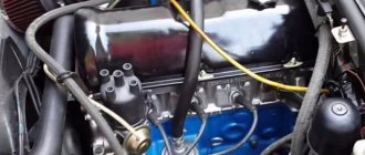
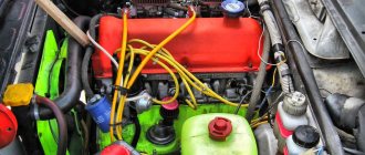
In the photo - VAZ 2106, which is an exact copy of the Fiat 124
Different ignition systems were installed on the car at different times, but the Fiat contact design is considered a classic. Its device is incredibly simple - an ignition coil, a distributor, a bundle of high-voltage wires and the right spark plugs. This is all that is needed for the correct operation of the engine. On the first batches of sixes, until 1980, a P125-B distributor of the simplest design without vacuum adjustment of the ignition timing was installed. After installing the standard Ozone carburetor, it became possible to equip the distributor with a vacuum advance angle adjustment system.
Structurally, distributors differ only in the presence of a vacuum membrane chamber, which is connected to the primary chamber of the carburetor. At a certain period, a distributor was installed without a vacuum chamber and it was structurally similar to the old one. Reel B117-a, sealed, filled with oil, with open magnetic conductors. In short, there is practically nothing to break. All that remains is to check the condition of the system elements and you can begin adjusting.
Features of UOZ
The ignition timing angle, or as it is usually designated, the ignition timing, has a number of features that must be taken into account for the stable operation of all components in the engine. The following features are noted:
- In engines that are injected, the OZ is installed independently, since the system has a similar function. The angle at the moment the motor is running is determined. The system is based on the readings of a three-dimensional function and engine load. The operating mode of the engine (winter-summer) and the speed at which the crankshaft rotates is also important. If all indicators correspond to the optimal parameters, the control system independently selects and sets the ignition timing;
- The optimal SOP for a particular engine, in turn, is determined by the speed at which the crankshaft operates. A special feature is the fact that a higher number of revolutions ensures a reduction in the time required for ignition;
- Temperature indicators also affect SOP. Low slows down oxidation processes, as a result of which the likelihood of an early ignition timing increases; high determines late ignition timing.
- The loads that the engine experiences are large and guarantee that there will be a high level of cyclic filling of the cylinder. In this case, it will be necessary to reduce the ignition timing. If this is not done, an explosion may occur in the engine, that is, detonation.
Replacing the VAZ 2106 distributor with your own handsAutoRemka
Distributor malfunctions lead to malfunctions in the ignition system. You can guess that the distributor is faulty by such characteristic signs as sudden jerks of the car while driving and discordant operation of the engine at idle.
The essence of such a procedure as repairing or replacing a VAZ 2106 distributor is to replace the worn parts included in it.
To carry out repair work you will need:
2 7 mm wrenches, 10 and 13 mm wrenches, two screwdrivers, a hammer, a set of flat feeler gauges, mandrels for knocking out and pressing in distributor bushings (bearings), and tweezers.
When all the tools are prepared, you can start working.
1. We unscrew the 2 fastening screws that secure the connection of the distributor rotor with the support plate of the ignition timing regulator, after which we remove the rotor itself.
2. The springs and weights of the centrifugal ignition timing regulator must be marked so as not to get confused during assembly and put everything in its original place.
3. Next, use a screwdriver to remove the springs of the centrifugal regulator (a screwdriver is needed to pry off the springs).
4. While holding the nut on the moving contact screw, unscrew the nut that secures the wire ends (the capacitor wire and the wire coming from the ignition coil).
5. Now you need to unscrew the screw that secures the distributor housing to the capacitor housing, then remove it.
6. Next, unscrew the screw that secures the tip of the movable contact wire (the nut must be held in place) and remove the insulating spacer, as well as the washers (spring and 2 flat washers - insulating and metal).
7. The next step is to unscrew the two screws that connect the contact group to the movable distributor plate.
8. After unscrewing the fastening screws, remove the contact group, followed by the insulating washers located on the axis of the contact group (flat and locking).
9. Next, use a flat screwdriver to pry off the washer that insulates the spring plate of the movable contact, and remove the movable contact itself from the axis of the contact group.
10. From the axis of the movable plate of the distributor, remove the lock washer located on the fastening of the vacuum regulator rod.
11. Use a screwdriver to pry up the vacuum regulator rod and remove it from the axis of the distributor plate.
12. Unscrew the two screws that secure the vacuum regulator housing to the distributor body and remove the regulator.
14. Press out the pin that secures the low-reflection coupling from the distributor shaft, then remove the coupling, followed by the washer.
15. Remove the distributor shaft from the housing.
17. Unscrew the 2 screws that secure the bearing locking plates, remove the spring washers and remove the plates using tweezers.
18. Next, remove the movable plate assembled with the bearing from the distributor body.
19. Check the condition of the distributor shaft - there should be no visible signs of wear on the surface of its contact with the bearing.
20. We check the capacitor using for this procedure a device that measures capacitance (normal values are in the range of 0.20-0.25 μF).
21. Then you should check the condition of the diaphragm of the vacuum ignition timing regulator (to do this, you need to press the rod and plug the fitting... the rod must be held by the diaphragm).
22. We inspect the contacts of the breaker - there should be no dirt, erosion or signs of burning on them. If the above-mentioned contaminants are present, the contacts should be cleaned using a velvet file (under no circumstances should sandpaper be used for this purpose) and washed with alcohol or gasoline.
23. The distributor housing bushing with signs of wear should be replaced with a new one. Pressing out and pressing of the bearing should be done using a mandrel of the appropriate diameter.
24. The distributor should be assembled in the opposite order to the disassembly order, taking into account the following features.
Upon completion of assembly, the distance between the breaker contacts should be adjusted. The gap should be from 0.35 to 0.45 mm.
The fold located on the movable plate of the distributor must be lubricated with engine oil (literally 2-3 drops of oil will be required). The same should be done with the bearing, adding a couple of drops of oil through the oiler, which is installed on the distributor body, and the splined part of the distributor shaft.
We carry out the adjustment ourselves
- The first step is to install the cylinder in the correct position. Installation is carried out so that the mark on the pulley is exactly at 0 degrees.
- Set how the slider is positioned. It should be aimed at the first pin in the cylinder.
- Use a strobe light and make sure the ignition is working properly.
- Make the electrical connections in the battery: minus to ground, plus to plus.
- The sensor must be connected to the high-voltage wire on the cylinder. The mark should connect to the crankshaft pulley.
- Start the engine at low speed (up to 800 rpm). Use a stroboscope to illuminate the pulley, and if the mark coincides with the middle mark, then the ignition is set correctly.
- Otherwise, the engine should be turned off and the meter should be loosened. In order to decrease the angle, turn the sensor clockwise; to increase it, turn it counterclockwise. Record and test the calibration again with the ignition on.
- Next, you should perform manipulations with the distribution sensor. Open the lid. Match the stator and rotor mark.
- Start the engine, bring the temperature to 75-80 degrees. When the speed is 50 km/h, sharply press the gas pedal.
- If the ignition was installed correctly, a short-term detonation will occur when you press the gas.
Also interesting: Phase sensor Niva Chevrolet symptoms of malfunction, DPRV high signal level
Then there are two possible developments: early and late ignition. Let's consider solutions for both cases:
- In the case of late ignition, when there is no detonation, you should change the position of the sensor clockwise.
- In the case of early ignition, when detonation lasts longer than necessary, the sensor is rotated counterclockwise.
Niva 21213 can be subject to adjustment of the starting system by the gap at the edges of the valves, if the carburetor is removed, or by the crankshaft speed directly on the car. In the first case, the gap at the location of the lower edge (in the direction of air movement) from the throttle valve is set to a width of 1.1 mm.
It is adjusted with a screw that has a 0.7 cm hexagon on the head and a slot from the shank. This operation is carried out with the cam lever turned counterclockwise from the starting system control (all the way). In the same position, the gap at the lower edge of the air damper is set to 3 mm using a screw in the cover from the diaphragm mechanism in the starting system (you need to loosen the lock nut).
The principle of powering a carburetor engine Adjusting the Niva starting system directly in the car saves time: You need to remove the air filter from the engine, pull the control lever towards you from the air damper, and start the engine. When the air damper is forced to open (by touching a flat screwdriver to a third of its full angle of rotation) using a screw (next to the lever on the axis from the throttle valve from the first chamber), the initial rotation speed is set to 2.08.mar.0 thousand.
If you have a gas analyzer, then the carburetor adjustment in the starting system part can be done based on the amount of CO (carbon monoxide) in the exhaust gases. If, with the choke control lever fully extended, the gas rate is 8%, then everything is in order. If there is less gas than this value, then the screw on the cover of the diaphragm mechanism is tightened; if there is more, it is unscrewed and repeated measurements are taken.
It is necessary to adjust the idle speed of the Niva 2121 so that there is less carbon monoxide in the exhaust gases and so that the engine runs stably. At service stations, such work is carried out with gas analyzers on the MV. In the garage, adjustments can be made using the tachometer.
Ignition coil device
To test this system, you will need an electrical device such as a multimeter, as well as screwdrivers with different heads and insulated pliers for working under voltage. It is necessary to observe safety precautions when working with the ignition system, because... high voltage electric current flows in the circuit. It is recommended to have rubber gloves or insulated pliers.
The schematic diagram of the VAZ 2106 ignition coil is located here. The figure shows how the ignition coil is connected in the standard version.
The ignition coil, the price of which is acceptable for most Russian motorists, has the nomenclature code 8352.12. and is an oil-filled tank with an open-type magnetic wire.
The standard ignition coil of the “six”, which is easy to buy at any specialized auto parts store, is equipped with 3 contact terminals: “B”, “K” and an output for the central high voltage wire. The ignition coil is connected in the following way: the positive wire of the battery is connected to terminal “B” through the ignition switch contact. Output “K” is connected to the output contacts of both windings of the ignition coils and the negative wire of the battery through the switch.
The high voltage output is connected to another contact of the secondary winding and a high voltage wire contact leading to the breaker distribution element, which, with the rotational movement of the slider, distributes the high voltage current to the spark plugs.
Checking the ignition angle while the vehicle is moving
It is best to check the functionality of the ignition system after any adjustment while driving. This is due to the design features of the distributor and the octane number of the gasoline used. It happens that the ignition angles set according to the marks do not provide sufficient dynamics and throttle response. Adjusting by ear according to the beginning of detonation will help:
- We accelerate the car to a speed of 45-50 km/h on a flat section of the road;
- We turn on direct transmission (fourth on the VAZ 2106) and press the gas pedal all the way;
- A characteristic ringing sound (detonation) should appear, which will disappear after 2-3 seconds, and the acceleration will be smooth and powerful without failures;
- If detonation does not disappear throughout the entire acceleration, then the ignition angle is “early”;
- The complete absence of ringing and sluggish dynamics indicate a delayed spark in the cylinders;
- We adjust the position of the distributor in place, turning it by 3-5 degrees;
- When the adjustment is completed, the position of the distributor body relative to the block is marked with a mark or paint.
Ignition adjustment work should be carried out regularly. The service interval for a simple contact ignition system is 15,000 km, for an electronic one - twice as long. The condition of the spark plugs and high-voltage wires is also regularly checked. All setup operations can be easily done independently; a garage is not needed for this. The skill of independently repairing the ignition of a VAZ 2106 will always come in handy on a long journey or in winter, when problems arise with starting.
How to install a distributor and configure it on a VAZ 2101 solved 1 answer
The first step is to remove the terminal from the battery, then disconnect the wires from the ignition coil, disconnect the central high-voltage wire, and remove the distributor cover. Next, you need to set the position of the slider so that it is rotated at an angle of 90° with respect to the engine. With this approach, replacing the distributor will have virtually no effect on the ignition timing. You unscrew the spark plug of the first cylinder, plug the spark plug hole with a rag, and begin to manually turn the crankshaft pulley clockwise, if you look at the engine against the movement of the car, until the rag jumps out of the spark plug hole. It is best to turn the engine with a ratchet wrench specially purchased for this purpose (or made independently according to a sample). In order for the position of the new distributor to be the same as the old one, you need to make a mark on the cylinder block as shown in the figure.
special instructions
In order for the work done to be of the highest quality, it is necessary not only to follow the step-by-step repair steps, but also to correctly carry out the first drive of the car. Its acceleration should not exceed 50 km/h. The test drive should be carried out on a flat road (it is better to choose an asphalt one).
After reaching a speed of 50 km/h, the speed switches to 4th. The gas pedal needs to be pressed sharply. Then you should pay special attention to such an indicator as “ringing of fingers” (or detonation). If it disappears in 1-2 seconds, then the ignition timing is set correctly and there are no problems with the operation of the components. The speed during this test should be 60 km/h.
It will be necessary to check all the actions performed for the absence of errors or carry out the work from the first steps if an incessant detonation knock is clearly audible. This is a signal that early ignition is taking place. In this case, it is recommended to first turn the toggle switch one division against the clock - to “minus”.
If detonation does not follow, you can make another turn, but this time in the “plus” direction - clockwise. It is planned to automate the process of adjustment work or subtuning if necessary - a vacuum regulator is used for this purpose. This method takes into account possible loads on the engine, which makes work easier.
Electronic ignition system design
1) Sensor-distributor, acting as a contactless distributor. 2) Switch, the functional purpose of which is to interrupt the current of the primary circuit of the ignition coil in accordance with the signals of the sensor-distributor. The circuitry of this device provides a mode for automatically shutting off the current passing through the ignition coil when the power plant is not working (the ignition is on). 3) An ignition coil that converts an intermittent low voltage current (12 Volts) into a high voltage current (10-20 Kilovolts), initiating a “breakdown” » air gap on the spark plug electrodes. 4) A set of wires. 5) A set of spark plugs that ignite the fuel-air mixture through a spark discharge. The use of spark plugs in BSZ that are not designed for a high-power spark discharge is not recommended, since they quickly fail due to overheating.
About the drive mechanism
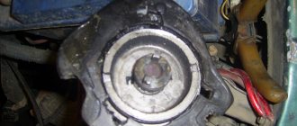
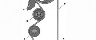
To transmit torque to the distributor shaft on the “six”, a helical gear is used, rotated by a timing chain (in common parlance – “hog”). Since the element is located horizontally and the distributor roller is vertical, there is an intermediary between them - the so-called fungus with oblique teeth and internal slots. This gear simultaneously turns 2 shafts - the oil pump and the distributor.
The distributor drive consists of two transmission gears with oblique teeth
Both transmission links - the “hog” and the “fungus” - are designed for a long service life and are replaced during engine overhauls. The first part is removed after disassembling the timing chain drive, the second is pulled out through the upper hole in the cylinder block.
The VAZ 2106 distributor, equipped with a contact breaker, is a rather complex unit consisting of many small parts. Hence the unreliability of operation and constant failures of the spark generation system. The non-contact version of the distributor creates problems much less frequently, but in terms of performance characteristics it still falls short of modern ignition modules, which have no moving parts.
Non-contact ignition system device
The schematic diagram of the VAZ contactless ignition of the sixth model is located below.
1. Contactless ignition distributor sensor. 2. Candles. 3. Shielded protection. 4. Non-contact type sensor. 5. Bobbina. 6. Generator element. 7. Ignition switch component. 8. Battery. 9. TC – transistor equipment with a switching circuit (transistor switch).
In such a complex, a non-contact ignition distributor is used to disconnect the low-voltage circuit, which works to open and close the electrical circuit, “locking” or “opening” the output transistor. This system allows you to increase the voltage on the electrodes of the spark plugs and, thereby, increase the energy of the spark discharge. At the same time, the voltage indicator on the spark plug elements does not decrease at low values of rotation of the crankshaft of the power plant, which makes the starting value of the motor much better.
Such non-contact ignition, the price of which is quite high, has significant advantages over the contact system.
Adjusting the ignition timing
For subsequent actions, use a 13 key to loosen the fastening nut of the distributor (ignition distributor). Connect one wire from the light bulb (it will act as a voltmeter, that is, indicate the presence of voltage) to the low-voltage terminal that the coil has, the second to ground. Now turn on the ignition
Slowly and carefully rotate the distributor body clockwise, stopping immediately when the light goes out. The sparks that appear will indicate the moment of ignition
Move the distributor counterclockwise until the contacts are disconnected and the lamp lights up again. Everything is in order, you can safely tighten the distributor, the setup is complete.
Main elements of the ignition system
Now we need to consider the common elements of all ignition systems. They are the same in all, regardless of whether the VAZ-2106 has an electronic ignition system or a contact one. Firstly, candles are everywhere. They consist of a central electrode, with a small gap between it and the ground. It is isolated from the body by a ceramic element. Rare candles live 30 thousand km. mileage, and some even collapse. They burn out so that part of the central electrode falls into the cylinder. For this reason, it is necessary to replace them in a timely manner.
Secondly, armored wires connecting high-voltage parts. They consist of a special fiber through which a high voltage pulse is transmitted. There are five wires in total - four for connecting the distributor cap to the spark plugs. And one is for connecting the coil to the distributor. Thirdly, it is present in all designs, although they have slight differences. Fourthly, the ignition coil is a transformer capable of tens of times increasing the voltage supplied to the primary winding. But the electronic ignition circuit of the VAZ-2106 turns out to be a little more complicated than that used in the classical system.
Switch
The last element in the circuit, the presence of which is required by a contactless electronic ignition system, is a switch. The ideal place in which it can be installed in a VAZ 2107 is between the washer reservoir and the left headlight. There is a flat area on which we will install the switch, with the radiator facing the body. Having leaned the switch, we mark the places for drilling holes in the body, through which we fasten it with self-tapping screws; in this case, you need to screw the black (neutral) wire from the connection block under one of the screws.
After completing all the work described above, you should once again carefully check the connection of the wires according to the circuit diagram. If everything is done correctly, you can try to start the engine. Usually there are no problems with this; all that remains is to adjust the ignition to ensure the most efficient operation of the engine.
Main elements of the ignition system
These include:
- Breaker-distributor. Initially, the first models until the 80s of the twentieth century were equipped with the R-125B device. It was equipped with a mechanical octane corrector, which adjusted the angular value of the ignition timing in a small range, but it was not equipped with a vacuum type regulator. After this, the ignition and fuel supply systems were modernized, as a result of which a distributor with a regulator of the vacuum operating principle and a compatible “Ozone” carburetor appeared.
- Bobbin B117-A is a contour type, with a disconnecting magnetic circuit, filled with special oil, sealed.
- Spark plugs A17DV or their export analogues.
- Ignition switch VK347 with an anti-theft gadget, operating on the following principle: after the ignition key is moved to position III “Parking”, a metal lock pops out of the body part, which falls into a special groove in the steering shaft and does not allow it to rotate.
For emergency repairs of the ignition system of a VAZ 2106 car, it is necessary to have in stock the parts that most often fail. This is a reel and a distributor capacitor; they do not take up much space. Unfortunately, they cannot be repaired.
DETAILS ABOUT THE MOST IMPORTANT ELEMENTS OF THE TRAMBER DEVICE
VACUUM REGULATOR
It is this device that can change the OZ if necessary. As soon as the motor load changes, appropriate adjustments are made to the operation of the distributor device parts.
The vacuum regulator of the distributor is a closed cavity. To ensure better performance, the design is divided by a diaphragm. One cavity goes directly to the carburetor.
When a vacuum occurs, the diaphragm begins to move. As a result, pressure is exerted on the movable disk and the breaker cam. The response time of the latter is adjusted depending on the current situation.
Adjustment how to set
It is recommended to use a special tool - a strobe light - to adjust contactless ignition. But if it is not there, you can use the following method.
- We set the distributor slider: unscrew the first spark plug, plug the hole with a finger and turn the crankshaft pulley. If air begins to press on your finger, it means you are on the compression stroke. At this moment, position the distributor so that the slider faces the first cylinder.
- Seize the moment of ignition. To do this, connect the central wire from the coil to the spark plug and short it to ground. Turn the distributor against the movement of the slider until the spark jumps from the spark plug. This point should be in the area where the slider interacts with the first cylinder.
- Set the ignition timing completely: with a warm car in second gear, give the gas sharply to the floor. When detonation is heard, set it later, if not, then set it earlier.
Setup video
Contactless ignition uses two important devices - a switch and a Hall sensor. The distributor and sensor must be compatible with each other. The new ignition coil must be an oil-filled type. It is better to take the wires for connecting the system from Niva.
In my free time, I read a lot, play airsoft (a team military sports game) and amateur radio communications. Lots of professional connections. My strengths: communication skills, endurance, responsibility.
Contactless distributor
The device of the distributor, functioning with the electronic ignition mechanism, is similar to the design of a mechanical distributor. This device also has a slider, a plate with a bearing, a vacuum corrector and a centrifugal regulator. However, the contact group and capacitor are replaced by a Hall sensor and a metal screen fixed on the shaft.
The contactless distributor in the 2106th model works as follows:
- A permanent magnet and Hall sensor are located on the moving section. A screen with slits rotates between them.
- As soon as the magnet field is blocked by the screen, the voltage is zero at the terminals and the sensor is inactive.
- When the roller rotates and overcomes the slot, the magnet field reaches the sensor surface. In turn, a voltage is generated at the output of the element, which is sent to the electronic unit (switch). The latter sends a signal to the coil, which generates a discharge going to the ignition slider.
The non-contact dispenser is more durable in operation. The bearing and Hall sensor fail less often due to the lack of mechanical stress.
Signs of incorrect ignition timing setting
These include:
- the vehicle does not reach the maximum speed of the power plant;
- increased fuel consumption;
- the engine idles unevenly;
- the engine unit overheats;
- After the engine stops running, detonation occurs.
Correct installation of the VAZ 2106 engine ignition system consists of 3 stages:
The first stage is a change in the angle of contacts that are in a closed form. The second stage is setting the ignition timing of the VAZ 2106, and the third is adjusting the ignition system while the vehicle is moving. This ignition setting is carried out when the “six” is equipped with a contact ignition system or a transistor switch is installed.
- Unfasten the latches of the breaker-distributor cover. With a contact system, we first clean its contact group with a needle file and test the degree of their interaction. If necessary, slightly tighten the fixed-type contact.
- Using a special key for rotating the crankshaft, we select a position of the product when the contact gap becomes extremely large (if it is absent, we put the manual transmission in the 4th gear position and select this moment by moving the vehicle).
- We unscrew the fasteners that secure the group of contacts on the bearing base.
- Using a special set of probes, we select a product with a 0.4 mm template and adjust the gap between the contacts so that the template hardly passes between the contacts.
- Screw in the fasteners and fix the position of the contacts.
- We carry out verification measurements with 0.35 mm and 0.45 mm probes. In the first case, free movement in the gap of the contact group is allowed, and in the case of the second probe, the passage of the template is not allowed.
Symptoms of a problem
Adjusting the ignition on a car is required after repairing the engine or removing the distributor. Like any mechanical system, it tends to wear out, and characteristic symptoms appear:
- The engine does not start or runs intermittently. If gasoline enters the carburetor, the reason lies in incorrect setting of the ignition angle or misalignment of the marks on the timing chain.
- Reduced acceleration dynamics and deterioration of motor elasticity. The mixture does not ignite at the optimal time, so efficiency decreases.
- Increased fuel consumption. This happens with late ignition, when in order to obtain the same dynamics you have to press the gas pedal more actively. Some of the gasoline does not have time to burn and flies out into the exhaust pipe.
- Late ignition causes a popping sound in the muffler when the unburnt fuel mixture ignites when the exhaust valve opens.
- Rough operation of the engine is possible with early ignition of gasoline in the cylinders. An explosion at the moment the piston does not reach TDC is the cause of the characteristic rattling sound and ringing.
An interesting article about biofuel produced from ordinary sawdust, read more here.
Having discovered a malfunction, you should check whether the ignition is installed correctly on the VAZ 2106, and if necessary, adjust it. To work, you will need a spark plug wrench, a “13” wrench, a light bulb or strobe light, and a plate probe.
Checking the coil
In the process of checking the performance of the coil, the first thing to do is check the voltage supply to it.
For this purpose, the voltage supply is turned on and then it is measured between terminal B+ and ground. This value is 12 V. If voltage is not supplied to the coil, then the reason for its absence should be sought in the lock. If normal voltage is present and there is no spark on the spark plugs, it is necessary to measure the resistance of the windings. To do this, the contacts of the measuring device are applied to two side terminals. For the primary winding, the resistance value should be 3-4 ohms.
The resistance of the secondary winding is within 7-9 Ohms. The coil cannot be checked for the presence of a spark by leaning the high-voltage wire against the motor body, since in this case the gap becomes so large that the increased resistance causes breakdown of the winding of the unit, and this leads to failure.
How to check the Hall sensor on Lada 2106: electronic ignition
This controller is the biggest problem on BSZ systems. Its verification will be carried out like this.
- Elimination method. The failed sensor is replaced with a known good one. To do this, you will need to purchase it or ask your neighbor for a whole sensor. If after installation the engine operation is leveled out, the part is replaced.
- The second method involves the following steps. To check, remove the terminal from the distributor and turn on the ignition. Next, you need to close contacts 3 and 6. If the sensor is damaged, a small spark will appear.
There are other testing methods that involve the use of a multimeter and other tests. We will not write about them here, since this will require special equipment and deep knowledge of auto electrics.
Malfunctions of the six ignition system
When operating a vehicle, the following malfunctions of the ignition system occur, which must be eliminated before further driving the vehicle.
| Malfunction | Remedy |
| The contact group has a coating of dirt, is oxidized or there are contact burn points, the distance between the contacts is increased | It is necessary to clean the contact group and adjust the gap |
| Weak fasteners or wiring caps in the low-voltage circuit have oxidized, a broken wire or a short circuit to the car body | Test the wiring and their connections, replace damaged sections of the circuit |
| Defective ignition switch (no contact closure) | Test the area, replace the defective contact element of the ignition switch |
| The capacitor is broken and does not hold capacity | Replace the product |
| There is no voltage in the primary type bobbin winding | Replace the product |
| Incorrect adjustment size in the distributor contact group | Set recommended size in contact group |
| Excessive wear of the PCB pad or increased diameter of the distributor lever bushing | Replace contact group |
| Defect in the bearing of the movable type distributor plate | Replace the bearing or the entire distributor |
| The ignition spark plug elements have an uncertain contact in the threaded part of the cylinder head, the spark plug caps from the insulated HV wires have broken or become oxidized; the insulated HV wires are dirty or their insulating layer is damaged | Test the contacts and, if necessary, restore the joints, clean or change the wiring |
| The corner of the distributor cover has undergone severe wear or has become defective and is in a non-contact state | Check the carbon of the distributor cap and, if necessary, replace it |
| Loss or loss of voltage through chips, through cracks or burnout points in the cover or rotor part of the distributor, as well as through a layer of soot or drops of moisture on the internal cavity of the distributor cover | Carry out a check, clean the cover from foreign layers of moisture and soot, replace the distributor elements (cover and rotor) if they are damaged |
| Failure of the resistance in the slider (distributor rotor) | Replace the slider resistance |
| The car bobbin has external or internal defects | Replace the car bobbin |
| The glow elements of the spark plugs (electrodes) are dirty with oil or the gap between the interacting elements is set incorrectly | Clean the spark plug elements and carry out adjustments to align the gap between the interacting elements |
| Ignition spark plug elements have external defects in the form of cracks and chips on the insulator element | It is necessary to replace spark plug elements with updated products |
| Incorrect connection of high-voltage wires to the contacts on the car distributor cover | Connect the high voltage wires according to the appropriate diagram (1-3-4-2) |
| Incorrect installation of the ignition in the vehicle | Test the installation of the MH and, if necessary, adjust it |
The table below will help you diagnose and troubleshoot problems that may arise.