Front suspension
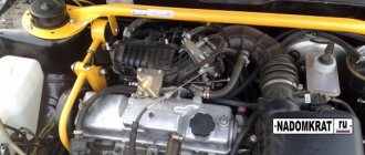
In fact, the front suspension design of the VAZ 2114 is much more complex than the rear one. Judge for yourself, because its design includes a total of 41 elements. The main one is the shock absorber strut. It is mounted on the steering knuckle using two bolts. The bolt passing through the holes of the rack bracket is equipped with an eccentric washer and a similar belt. When the steering gear is turned, the top bolt also turns. This causes the entire car to turn.
Front design
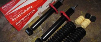
The weakest point of the front suspension is the shock absorber struts. The main task falls on them, and therefore the load is corresponding.
Disassembly and replacement
Many VAZ 2114 owners dream of installing air suspension. These are completely feasible fantasies, which, however, will require serious financial investments from you.
Clamp
Therefore, if you have not yet saved up enough money for pneumatics, and the knocking in the front suspension of the VAZ 2114 haunts you, you will have to disassemble it, determine the causes of the malfunctions and put the entire structure back together. How to do it? Now we'll tell you.
- The car can be lifted using a lift, or simply placed on a viewing hole. It all depends on what resources you have. Be sure to apply the handbrake, remove the wheel caps, loosen the bolts and remove the hub nuts. The front must be effectively locked in order to remove the wheels.
- Now remove the ball joint pin. It is located in the swing arm on the A-pillar. After this, the front stabilizer strut is removed. It will have to be disconnected from the front suspension arm. Only now can you remove the stretch marks from the body. The next step will be to remove the ball joint. In case you forgot, it is located and attached to the steering knuckle.
- Now we proceed to remove the front suspension arm. To do the job as competently as possible, unscrew the bracket attached to the body. Now remove the lever along with the extension and bracket. Don't forget to remove the bolts securing the pads to the steering knuckle.
- Well, now in front of you is a fully assembled caliper. It is not recommended to completely remove it, since reassembling it can lead to unpleasant consequences and unnecessary financial costs. It is better to take a hook and hang it so that there is no load on the main hose. Next, you can press the splined shank out of the hub.
- Go to the engine compartment and from there remove the protective cam. For such an operation, you will need to unscrew the nuts on the telescopic strut, and then remove the strut from the suspension of the front of the car. It comes immediately with the hub and steering knuckles. The second strut of the front suspension is dismantled in the same way, and then the struts are removed from the bar.
- When removing the ball joint and steering knuckle bolts, be sure to use only socket wrenches. If you neglect this rule, you risk severely damaging the protective cover of the hinge. By doing this, you will incur unnecessary financial expenses on yourself.
- As you dismantle, inspect the condition of certain suspension elements and replace them if necessary.
- The assembly process is carried out almost entirely by analogy with disassembly. But there are a couple of nuances. The first is when installing the fastening bracket to the body, try not to damage the threads, so work carefully. Second, when installing the anti-roll bar, try not to cause longitudinal displacement of the cushion on the bar.
Working with the front and rear suspension of a VAZ 2114 requires increased concentration and knowledge of the structure of this unit. Therefore, before starting repairs, be sure to familiarize yourself with the suspension diagram and study the recommendations from the operation and repair manual. You can even watch several video tutorials that clearly explain the replacement and repair of front and rear suspension elements.
If your own experience is not enough, it is not worth adding to it, starting with similar work. It is better to immediately contact the specialists of a trusted service station. It will cost extra money, but the result of the repair will be completely worth it. Driving a faulty car is definitely not the solution to the problem.
Samara 2 (VAZ-2115). Disassembly and assembly of suspension units
Home Cars - VAZ VAZ-2115 (Samara 2) 1997+ - maintenance and repair manual
search site
content .. 51 52 53 ..
Samara 2 (VAZ-2115). Disassembly and assembly of suspension units
Disassembly
| Rice. 4.1. Front suspension assembly: 1 – upper support of the telescopic strut; 2 – upper support cup; 3 – compression stroke buffer with protective casing; 4 – compression buffer support; 5 – suspension spring; 6 – lower spring support cup; 7 – steering rod ball joint; 8 – steering knuckle; 9 – telescopic stand; 10 – eccentric washer; 11 – adjusting bolt; 12 – rack bracket; 13 – steering knuckle; 14 – front brake protective cover; 15 – brake disc; 16 – retaining ring; 17 – wheel hub nut; 18 – splined shank of the wheel drive hinge housing; 19 – guide pin; 20 – wheel hub bearing; 21 – ball joint; 22 – suspension arm; 23 – adjusting washers; 24 – stabilizer strut; 25 – stabilizer bar; 26 – stabilizer bar cushion; 27 – stabilizer bar mounting bracket; 28 – body bracket for mounting the suspension arm; 29 – suspension arm extension; 30 – bracket for fastening the extension; 31 – protective cover of the ball pin; 32 – ball pin bearing; 33 – ball pin; 34 – ball pin body; 35 – suspension strut rod; 36 – outer body of the upper support; 37 – inner body of the upper support; 38 – upper support bearing; 39 – rubber element of the upper support; 40 – travel limiter of the upper support; 41 – protective cap of the upper support; B - zone for monitoring the suspension joint |
Apply relative position marks on the head of the adjusting bolt 11 (see) and on the strut bracket so that during assembly the marks can be aligned to approximately maintain the camber of the front wheels. Then unscrew the bolts securing the steering knuckle 13 to the strut bracket and remove the steering knuckle as an assembly with the hub. Do not press the wheel hub out of the bearings unless necessary, as pressing it out may damage the bearing. If the wheel hub or the bearing itself is damaged, press out the hub and bearing using a press and mandrels 67.7853.9583 and 67.7853.9587.
| Rice. 4.5. Steering knuckle and parts of the front wheel hub: 1 – steering knuckle; 2 – outer mud ring; 3 – hub bearing; 4 – wheel hub; 5 – thrust washer; 6 – nut; 7 – retaining ring; 8 – internal dirt ring |
When pressing out the hub, the bearing may be disassembled and the outer half of the inner ring may remain on the hub. In this case, it must be removed with a universal puller. For this purpose, there are two special recesses in the hub. Then remove the retaining rings 7 () and use the mandrel 67.7853.9587 to press the bearing out of the steering knuckle. If the hub bore diameter is damaged, replace it.
The procedure for installing a new bearing is as follows:
| Rice. 4.6. Pressing the bearing into the steering knuckle: 1 – steering knuckle; 2 – bearing; 3 – mandrel |
– install the outer retaining ring 7 (see ) into the steering knuckle 1 and press in the bearing 3. At the same time, make sure that the mandrel 3 () presses only on the outer ring of the bearing, otherwise it may be damaged;
| Rice. 4.7. Pressing in the wheel hub: 1 – mandrel; 2 – steering knuckle; 3 – hub |
– install the internal retaining ring and begin pressing the hub using mandrel 67.7853.9530. When pressing it in, mandrel 1 () must rest on the inner ring of the bearing. After installing the steering knuckle assembly with the hub on the car, install a new or used, but on another car, nut and tighten it to a torque of 225.6–247 N·m (23–25 kgf·m) and lock it.
Unscrew the bolts securing the protective casing 14 (see) of the brake disc and remove it.
| Rice. 4.8. Dismantling the front suspension strut: 1 – device 67.7823.9545; 2 – telescopic stand; 3 – spring |
| Rice. 4.9. Front suspension elements: 1 – protective cap; 2 – limiter of the compression stroke of the support; 3-upper rack support; 4 – upper support bearing; 5 – upper spring cup; 6 – front suspension spring; 7 – adjusting bolt; 8 – eccentric washer; 9 – protective casing; 10 – compression progress buffer |
Install the suspension strut into fixture 67.7823.9545 (), compress the suspension strut spring. Holding the rod with wrench 67.7812.9535, unscrew the nut on the rod using wrench 67.7812.9533. Remove limiter 2 (), upper support 3 assembled with bearing. Having unloaded the spring 6, remove it and the upper support cup 5, and then the compression stroke buffer 10 with casing 9.
Before further disassembling the rack, check its condition. With the rack in a vertical position (rod up), perform several full stretch-compression strokes, after which the rod should move without dips or jams and there should be no knocks or extraneous noise. Liquid leakage, deformation and destruction of the rack body, support cup, brackets and rack swing arm are also not allowed. Slight sweating at the top of the strut housing is not a sign of malfunction and does not warrant replacement or repair of the strut strut.
Carry out a more accurate assessment of the performance of the rack on a dyno using the diagram taken, as indicated above.
| Rice. 4.10. Removing the compression stroke limiter support: 1 – mandrel; 2 – compression stroke limiter support; 3 – rack bracket |
If it is necessary to repair the rack, clamp its bracket in a vice so that its jaws are perpendicular to the jaws of the vice (). With this fastening, the possibility of deformation of the rack is eliminated.
Disassemble the rack using tool kit 67.7824.9518 in the following order:
– remove support 2 (see) of the compression stroke buffer, to do this, tap the support with light blows of a hammer on a flat drift from bottom to top and in a circle;
| Rice. 4.11. Unscrewing the nut of the strut housing: 1 – wrench 67.7811.9510; 2 – nut |
– unscrew the housing nut with a wrench 67.7811.9510 (), remove the working cylinder assembled with the rod and its parts from the rack housing;
| Rice. 4.2. Telescopic stand: 1 – compression valve body; 2 – compression valve discs; 3 – throttle disk of the compression valve; 4 – compression valve plate; 5 – compression valve spring; 6 – compression valve cage; 7 – recoil valve nut; 8 – recoil valve spring; 9 – recoil valve plate; 10 – recoil valve disc; 11 – throttle disk of the recoil valve; 12 – piston; 13 – bypass valve plate; 14 – bypass valve spring; 15 – plunger; 16 – plunger spring; 17 – rod guide bushing with a fluoroplastic layer; 18 – guide bushing cage; 19 – sealing ring of the rack housing; 20 – rod seal; 21 – oil seal cage; 22 – gasket of the rod protective ring; 23 – rod protective ring; 24 – nut of the strut body; 25 – compression buffer support; 26 – rod; 27 – spring cup; 28 – rotary lever; 29 – rod limit sleeve; 30 – rack body; 31 – cylinder; 32 – drain tube |
– remove the protective ring 23 from the rod (see ), gasket 22, race 21 assembled with oil seal 20;
– by pressing on the compression valve plate, drain the liquid from the cylinder, to do this, repeatedly move the rod by the amount of its full stroke, without hitting the compression valve, so as not to deform its holder;
– having installed the compression valve in the mandrel from kit 67.7824.9518, clamp it in a vice and lightly rock the cylinder by hand until the compression valve is disconnected from the cylinder;
– pushing the rod down, remove the piston assembly with the rod through the lower hole of the cylinder; At the same time, make sure that the fluoroplastic coating of the guide bushing is not damaged;
– hold the rod in a vice by the flats on its shank and unscrew the nut 7 (see) of the recoil valve, then remove the parts of the recoil valve, piston 12 and parts of the bypass valve from the rod;
– having freed the rack body from the vice, drain the liquid from it;
| Rice. 4.12. Removing the rod guide bushing: 1 – guide bushing; 2 – cylinder |
– carefully use a copper hammer or a special drift to knock out the guide sleeve () from the working cylinder; At the same time, make sure that no nicks appear on the cylinder;
| Rice. 4.2. Telescopic stand: 1 – compression valve body; 2 – compression valve discs; 3 – throttle disk of the compression valve; 4 – compression valve plate; 5 – compression valve spring; 6 – compression valve cage; 7 – recoil valve nut; 8 – recoil valve spring; 9 – recoil valve plate; 10 – recoil valve disc; 11 – throttle disk of the recoil valve; 12 – piston; 13 – bypass valve plate; 14 – bypass valve spring; 15 – plunger; 16 – plunger spring; 17 – rod guide bushing with a fluoroplastic layer; 18 – guide bushing cage; 19 – sealing ring of the rack housing; 20 – rod seal; 21 – oil seal cage; 22 – gasket of the rod protective ring; 23 – rod protective ring; 24 – nut of the strut body; 25 – compression buffer support; 26 – rod; 27 – spring cup; 28 – rotary lever; 29 – rod limit sleeve; 30 – rack body; 31 – cylinder; 32 – drain tube |
– remove spring 16 (see) and plunger 15 of the hydraulic buffer from the cylinder;
– disassemble the compression valve, for which remove the holder 6, and then successively remove spring 5, plate 4 and valve discs 2 and 3 from the body.
Assembly
Assemble the front suspension strut in the reverse order of disassembly, taking into account the following:
– ensure the cleanliness of the workplace and all parts of the rack;
– make sure that there are no foreign impurities in the liquid, filter it if necessary;
– make sure that the threads of the recoil valve nut are not damaged when unscrewing it with an open rod;
– inspect the rod at the core location; if the deformation of the thread is large and does not allow screwing on the recoil valve nut without damaging its thread, upset the rod thread at the core location;
– the throttle disc of the front strut recoil valve has three grooves along the outer diameter, and the throttle disc of the rear shock absorber has four;
– the throttle disk of the front suspension strut compression valve has three grooves along the inner diameter, and the throttle disk of the rear shock absorber has two;
– tighten the recoil valve nut to a torque of 12.7–17.5 N m (1.3–1.8 kgf m), then lock it by opening the threaded end of the rod in previously undeformed areas; the moment of unscrewing the nut after opening must be at least 19.6 N m (2 kgf m);
– it is recommended to replace the oil seal and O-ring of the strut housing with new ones during repairs;
– fill the working surface of the oil seal (between the sealing edges) with CV joint grease-4 in an amount of 0.3–0.4 g;
– fill the strut body and cylinder with (320±5) cm3 of liquid for shock absorbers, and fill the rear shock absorber with (250±5) cm3;
– tighten the strut housing nut with the rod fully extended using the wrench 67.7811.9510/11, the tightening torque is 117–147 N m (12–15 kgf m) (for the rear shock absorber the tightening torque is 69–88 N m (7–9 kgf m) m);
– after tightening the nut, caulk the strut body. The torque for unscrewing the nut after caulking must be at least 294 N m (30 kgf m);
– after assembling the compression valve, make sure there is free movement of the valve discs and discs;
– press the compression valve into the cylinder using a special mandrel from the kit 67.7824.9518, then once again make sure there is free movement of the plate and discs;
– to install and press the rod guide bushing into the cylinder, use a special mandrel from the kit 67.7824.9518;
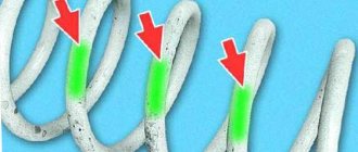
– install springs of the same class on the suspension.
| NOTE Springs are divided into two classes according to their length under the control load: A and B. Class A springs are marked with yellow (white)* paint on the outside of the middle turns, and class B springs are marked with green (blue)* paint |
In exceptional cases, if class A springs are installed on the front suspension, but there are no springs of this class for the rear suspension, it is allowed to install class B springs on the rear suspension. But if class B springs are installed on the front suspension, then install only class B springs on the rear suspension .
Disassembly and assembly of the suspension arm, brace and bracket
Disassembly
Having noted the number of adjusting washers 23 installed at the ends of the extension (see), unscrew the nuts and disconnect the extensions from the suspension arms 22 and from the brackets 30.
| Rice. 4.13. Pressing out rubber-metal hinges from the suspension arm and the brace mounting bracket: 1 – bushing; 2 – suspension arm; 3 – rubber-metal hinge; 4 – mandrel; 5 – device 67.7823.9540; 6 – bracket for fastening the brace; 7 – rubber-metal hinge; 8 – mandrel |
If the rubber-metal joints of the lever and extension are worn, damaged or destroyed, press them out. To press out and press in the extension joint, use a special tool. Press out and press the lever joint and the front extension joint with tools 67.7823.9535 and 67.7823.9540 ( and ).
| Rice. 4.14. Pressing in rubber-metal hinges: suspension arm and brace mounting bracket: 1 – mandrel; 2 – rubber-metal hinge; 3 – guide sleeve; 4 – suspension arm; 5 – support sleeve; 6 – mandrel; 7 – rubber-metal hinge; 8 – bracket for fastening the brace; 9 – support sleeve; A - surface with hinge markings |
Before pressing in rubber-metal hinges and rubber bushings, generously lubricate the hinge sockets and their outer surface with a 30–35% soap solution or IGP-30 oil. Observe precautions to prevent damage to the hinges during pressing (the appearance of scoring, cracks or tears of rubber).
After pressing, the hinges should be symmetrically located in their sockets and should not have any places drawn into the sockets or bulging out of them.
After pressing the hinges and before starting to operate the vehicle, it is necessary to wait at least 24 hours.
When pressing the front brace joint into the bracket, install it with the marked part facing out. The marking is applied on surface “A” (see) of the thrust collar of the smaller diameter hinge.
Assembly
| Rice. 4.15. Assembling a suspension arm with a stretcher: 1 – stretcher; 2 – suspension arm; A - distance between the axis of the lever and the center of the extension |
When assembling a lever with a stretcher, reinstall the removed adjusting washers so that the chamfers on them face toward the thrust end of the stretcher. Before tightening the extension nut, install the lever and the extension on a special device that provides a distance A () between the axis of the lever and the center of the extension equal to 10 mm, and fix the extension. In this position, tighten the extension fastening nut to a torque of 160–176.4 N·m (16.3–18 kgf·m). Then remove the lever assembly from the device and install adjusting washers at the other end of the extension, following the rules for their installation. Then secure the bracket with a nut, tightening it only until the gap in the joint is selected. Carry out the final tightening of the nut on the vehicle as indicated in the chapter “Installation of components and parts of the front suspension”.
When installing protective covers for ball joints, put 6 g of ShRB-4 lubricant into each cover.
Dismantling and assembling the upper support of the suspension strut
If wear, damage, or corrosion appears on the bearing of the upper support of the telescopic strut, it should be replaced. To do this, use a special mandrel to flare the support body, and then, using mandrel 67.7853.9588, press the bearing out of the support body under a press, using stand 67.7822.9530.
| Rice. 4.16. Crimping the support body: 1 – mandrel; 2 – upper support; 3 – stop |
Before pressing in a new bearing, make sure that there are no burrs or burrs in the bearing seat. Eliminate any irregularities found using fine-grained sandpaper. Using a mandrel 67.7853.9588, press the bearing into the support body, then crimp the support body on a press in four equally spaced places that were not previously deformed, using a special mandrel () for this purpose. After compressing the support housing, the bearing should not move in the axial direction. The pullout force of the outer ring must be at least 5880 N (600 kgf).
If it becomes necessary to replace the bolt securing the upper support to the body, press it out. After pressing in the new bolt, to ensure reliable fixation, weld its head at one point using electric arc welding. At the same time, avoid overheating of the support, as well as contact with splashes of metal and slag.
Press out worn, damaged or destroyed rubber-metal hinges of the stabilizer struts using a press using special mandrels, as indicated in half section. “Disassembly and assembly of the suspension arm, brace and bracket.”
When assembling the anti-roll bar, install the mounting brackets at a distance of 350 mm from the center line of the bar.
Checking technical condition
Telescopic stand
Wash all parts with kerosene and dry. Carefully check that the parts meet the following requirements:
– the disks of the compression and rebound valves, as well as the bypass valve plate, must not be deformed; non-flatness of the bypass valve plate is allowed no more than 0.05;
– the working surfaces of the piston, piston ring, guide bushing, rod, cylinder, recoil buffer plunger and valve parts must be free of scuffs, dents and signs of wear that could affect the normal operation of the strut;
– the working edges of the oil seal must be free of damage or wear;
– risks, scuffing and peeling of the fluoroplastic layer at the rod guide bushing are not allowed;
– the springs of the recoil and compression valves, as well as the plunger of the recoil buffer, must be intact and sufficiently elastic;
– the inner surface of the rack body must be clean, without marks or damage, the threads must be in good condition; check the tightness of the rack housing with air at a pressure of 0.3 MPa (3 kgf/cm2); air leakage is unacceptable;
– the rack body, bracket, spring cup and swing arm must not be deformed or damaged;
– the compression stroke buffer and the protective casing must not be damaged or destroyed.
Welding work on the rack is not allowed, as this may affect changes in wheel alignment angles and the performance of the rack.
Suspension arms
The deformation of the suspension arms is determined by tool 67.7851.9508. The suspension arm assembly with the ball joint is installed so that the centering mandrel articulates with the cone of the arm's ball joint pin, and the mounting pins of the device fit into the middle and outer holes of the arm.
A sign of deformation is the impossibility of inserting the lever mounting pins without force or poor articulation of the mandrel along the cone of the hinge pin.
Ball joints
Make sure the protective covers of the hinges are intact. Tears, peeling of rubber from metal fittings, traces of lubricant leakage through the cover are unacceptable. A slight squeeze of lubricant through the sprue hole in the ball joint housing, located in the upper part of the housing, is allowed.
Check for wear on the ball joint working surfaces by manually turning the ball joint. Significant (over 0.7 mm) free movement of the finger or its jamming is unacceptable.
| Rice. 4.17. Checking the ball joint on device 02.8701.9502: 1 – ball joint; 2 – indicator; 3 – torque wrench; 4 – device 02.8701.9502; A - diagram for checking radial clearance; B - scheme for checking axial clearance |
An accurate check of the condition of the ball joint based on the radial and axial clearance is carried out using fixture 02.8701.9502. To do this, install the ball joint 1 () into the socket of the device and tighten it with a screw. Install indicator 2 into the fixture bracket so that its leg rests against the side surface of the hinge body and the indicator arrow is at zero.
Install torque wrench 3 in the upper socket of the device and, applying a torque of 196 N m (20 kgf m) to it alternately in both directions, determine the total radial clearance in the ball joint using the indicator. If it exceeds 0.7 mm, replace the hinge with a new one.
Similarly, check the axial play in the ball joint, having first changed its fastening in the device, as indicated in. The axial clearance in the hinge is allowed no more than 0.7 mm.
Anti-roll bar
Check whether the rod is deformed and whether its ends are in the same plane; if the deformation is insignificant, then straighten the rod; if the deformation is significant, replace the rod.
Check the condition and safety of the cushions in the boom brackets. If the cushions are worn or damaged, replace them.
Check the deformation of the stabilizer struts with a gauge; If the gauge pins do not fit into the post holes, replace it.
Suspension springs
Inspect the springs carefully. If cracks or deformation of the coils are found, replace the spring with a new one.
| Rice. 4.18. Parameters for checking the front suspension spring: H - spring length under load |
To check the spring, press it three times until the coils touch. Then apply a load of 3188 N (325 kgf) to the spring. The length of the spring “H” () under the specified load must be at least 201 (182)* mm. Compress the spring along the axis of the spring; The supporting surfaces must match the surfaces of the support cups on the telescopic stand.
If a spring with a yellow marking (class A) has a length of less than 207 (188)* mm, change its marking to green (class B).
Stretch marks
The deformation of the stretch marks is determined by device 67.7851.9509. If there is slight deformation, straighten the stretcher using a press; if straightening is impossible, replace the stretcher with a new one.
Rubber-metal joints
The signs that determine the need to replace the hinges are described above (see “ Determining the condition of suspension parts on a car ”).
Upper support of telescopic stand
| Rice. 4.19. Checking the elastic deformation (settlement) of the upper support: A - control size |
Check the elastic characteristics (settlement) of the upper support by applying a load of 6860 N (700 kgf) to the support bearing () and measuring the distance “A” from the end of the bearing to the end of the outer housing of the support. This distance should not exceed 29 mm. Otherwise, replace the support with a new one.
Make sure that the bearing has no axial movement in the support housing. The bearing must not become corroded, damaged or seized due to wear. In these cases, replace the bearing with a new one.
Check the condition of the support housing. Peeling of rubber, rips, and cracks of the support are not allowed.
Features of replacing silent blocks of front levers
So, you have decided that replacing the silent blocks of the front control arms is inevitable. You shouldn’t immediately rush to the service station.
With proper preparation and the necessary tools, you can do the job perfectly on your own. The main thing is to act in the following sequence:
1. Prepare the necessary equipment and tools for work.
You will need:
- Set of socket and socket wrenches,
- special device for pressing,
- hammer,
- vice and chisel.
2. Buy the necessary replacement parts. Here you can choose two options: silent blocks “Balakovo” or “SEVI”.
3. Install the machine on an inspection hole or overpass. If your car has a crankcase protection, remove it.
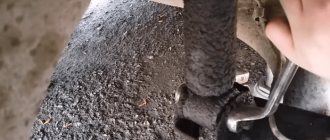
4. Unscrew the nuts that secure the front arms. Next, using a “17” wrench, unscrew the nut from the bolt that secures the stabilizer to the lever.
Now all that remains is to get the bolt itself. It is unlikely that you will be able to do this by hand, so you can tap it with a hammer.
5. Remove the bolts on the front wheel, lift the desired side with a jack and move the wheel to the side.
6. Proceed to the next task - unscrewing the nuts of the guy wires. This task is one of the most difficult.
Here you can't do without a key with good leverage. In addition, before you start unscrewing it would be a good idea to treat the nut with WD-40 (this will greatly simplify the task).
7. After removing the nut, pull the ball joint and move it away from the steering cam. There are a couple more bolts there - unscrew them and remove the lever.
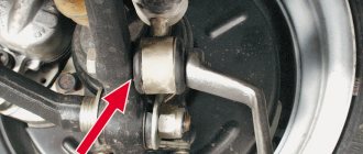
Attention! Point 8 applies to the VAZ 2109 and similar ones, on the VAZ 2110 there are no crabs, the extension is attached to the cross beam, it also has a silent block, as in the picture, if it is broken, it also needs to be replaced.
8. If you still cannot unscrew the extension nut, then dismantle the lever together with the “crab” and the extension – this will be much faster and easier (just slightly unscrew the nut near the “crab” and twist the three bolts that secure the “crab” to car body).
After this, you can continue to “struggle” with the extension nut, but in a more comfortable position.
9. Dismantle the silent blocks of the extension using a regular chisel and thoroughly clean the eyes from dirt.
10. Press in new silent blocks using a vice and hammer. As a rule, a few precise blows are enough for the knot to sit in place.
You can “put” the silent lock in place without a vice, but in this case you may need a sledgehammer. But remember that in this case there is a danger of damaging the node itself. So, it's better to use a vice to be sure.
11. Change the silent block on the front arm. The best option is if the old node is already broken. In this case, its extraction is not difficult.
All you need to do is take out the metal sleeve and use a screwdriver to remove the excess rubber. If this does not work, then press out the assembly.
12. Lubricate the new silent block thoroughly with soapy water (you can use dishwashing detergent) and put it in place.
During the pressing process, constantly monitor the edges of the silent block
If they start to curl up, carefully straighten them with a screwdriver.. 13. Put everything back in the reverse order.
Put everything back in reverse order.
13. Return everything to its place in reverse order.
That's all. Replacing silent blocks on a VAZ 2110 car is a job that you can easily handle on your own.
The only problem is the selection of a special tool for pressing out silent blocks.
But if you set yourself a goal and believe in success, then you will succeed. Good luck on the roads and of course no breakdowns.
Sources
- https://vaz-russia.ru/remont-vaz-2110/zamena-saylentblokov-perednih-ryichagov-na-vaz-2110-vaz-2112.html
- https://luxvaz.ru/vaz-2110/50-zamena-perednih-saylentblokov.html
- https://remontavtovaz.ru/vaz-2110/instrukciya-po-zamene-sajlentblokov-perednix-rychagov-na-vaz-2110.html
Rear suspension
For the rear suspension, it is better to replace the silent blocks by removing the beam, although this can also be done directly on the car. The installation of the rear rubber bushings is identical to that on the front beam. Pressing out and installation is best done using a mounting device.
However, if it is not there, then the especially “stubborn” ones will be knocked out of the rear silent bars of the VAZ 2110 by holding the part in which they are located in a vice. A mandrel is used, sometimes even sawed.
A faulty rear suspension manifests itself by the appearance of a characteristic knocking sound from the rear. Details: https://vazweb.ru/desyatka/podveska/zadnyaya-podveska.html
Both rear silent blocks are oriented along the lever and pressed flush against the end of the eye.
How to replace the silent block of the rear beam of VAZ cars
Hello dear readers of the blog RtiIvaz.ru. Today I want to talk about the silent block of the rear beam - the ease of replacement on VAZ cars when doing DIY repairs.
Silent blocks and various suspension parts from the factory are quite reliable and last a long time. Typically, their longevity depends on how you operate and maintain the car and usually last for 80-90 thousand kilometers. Salentblock find out what it is here.
Let's first look at the signs of wear on the silent blocks of the rear beam. When cornering, the car loses stability and uneven tire wear occurs. Or, when driving over potholes and bumps on the road, impacts appear on the body and an unpleasant creaking sound occurs in the rear of the car.
Unpleasant sounds when driving can also occur due to other malfunctions. Knocks can come from one place and be heard in another, especially as they move along they are heard in the rear of the body. Therefore, first you need a thorough diagnosis of the entire rear and front suspension: you will have to check the struts, bearings, supports, muffler, etc.
Having finally made sure that the rubber silent blocks are extremely worn out, we proceed to replacing them. Fortunately, compared to foreign cars, replacing the silent block of the rear suspension of VAZ “nine” or “ten” cars is distinguished by its simplicity and low cost.
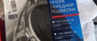
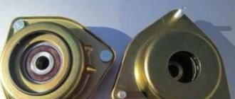
To begin with, let’s buy rubber bushings “fungi”, that is, silent blocks for the rear beam in a car store. For VAZ 2108 cars; 2109; 21099 you need to purchase silent blocks with the VAZ design number 2108-2914054-10, and for VAZ 2110 cars; 2112; 2114; 2115 VAZ design number 2110-2914054 is prescribed.
It is difficult to distinguish these silent blocks of these cars from each other, because they are very similar, but different in outer diameter (see the difference in the photo). You will not be able to install silent blocks from the “nine” VAZ 2109 on the beam of the “tens” VAZ 2110, as they will dangle. But the rubber bushing from the “ten”, if you try, can be pressed into the “nine” beam.
It will be useful: Do-it-yourself modification of the frets of the grant: video instructions
Step-by-step replacement of rear beam silent blocks on VAZ 2108 vehicles; 2109; 21099; 2110; 2112; 2114; 2115:
- 1. Replacement of silent blocks should be carried out on an overpass, inspection pit or lift, installing the machine in a way accessible to you.
- 2. Remove the rear wheel so that it does not interfere.
- 3. On the left side, disconnect the rear brake pressure regulator rod from the beam (see photo number 1.) On the right side, remove the handbrake cable to the side (see photo number 2.)
- 4. Using a “19” wrench, unscrew the nut from the bolt securing the rear beam to the bracket (see number 3 in the photo)
- 5. We remove the fastening bolt with a hammer, and then knock it out with a wrench (see number 4 in the photo.)
- 6. Next, lift the car body with a jack and move the beam eye down
- 7. We insert a wooden block between the body and the beam
- 8. Using a hammer and a drift, knock out the rubber bushings of the rear beam
- 9. Having cleaned the seat from dirt and rust, generously lubricate it with a thick soap solution and also lubricate the rubber bushing itself
- 10. Using a tool, press in the bushing. If there is no device, then we hammer it in with a hammer, hitting the head of any suitable bolt inserted with a washer of larger diameter, but so that the washer fits tightly to the rubber
- 11. Then we pull out the wooden block
- 12. Using a jack, we lift the beam and put on our original fastening bolt, then we attach the nut
- 13. Having placed the rear wheel, lower the car
- 14. Open the trunk door, then sit down on the bumper and press the back of the car as far as possible with all our weight.
- 15. Tighten the silent block mounting bolts until they stop
Actually, the work itself doesn’t seem to be difficult if you have a puller. And if it is not there, what should you do then? Therefore, I am writing for those who repair a VAZ car with their own hands. There is no need to complicate the task if you don’t have a special remover. Listen to the advice of car mechanics: do not fool your head and knock out - hammer in the silent blocks on the beams with a hammer.
Design number of the rear suspension arm mounting hinge: VAZ 2110-2914054
Design number of the rear suspension arm hinge: VAZ 2108-2914054-10
Design number of the rear suspension arm hinge: VAZ 1111-2914054
Video:
How to change daisies on a VAZ 2114: watch the video, study the instructions
Are you planning to implement a solution to the question of how to change daisies on a VAZ 2114, you’ve already watched the video, now are you preparing a sequential instruction for yourself? Then you can pay attention to the following workflow structure
- The machine is installed on a lift or driven onto an overpass to provide access to the front suspension, the elements of which will be used for repair work. Usually, the approach to the silent block is also made difficult by the crankcase protection, which must first be dismantled.
- Next, work with fasteners is provided, but due to the fact that the car has mileage and has been used in different weather conditions, a situation may arise that all the nuts have soured, or the threads are covered with a layer of dirt. What to do? Take a rag or a wire brush with stiff bristles and clean all existing fasteners. If some nut does not give in, then you should use special lubricant WD 40. And start unscrewing the suspension nuts again.
- First, we unscrew the bolts on the wheels, put the car on a jack and stoppers, and then think about how to change the daisies on a VAZ 2114, having previously pressed them out.
- We continue to work with the support and its dismantling. Sometimes it can be difficult to remove the support from the steering knuckle.
- Using a chisel, we begin to press out the silent block itself. Sometimes even fire is used, but in this situation you need to be very careful.
- We thoroughly clean the freed bushing, and immerse the new silent block in water for several minutes and wash it several times with a soap solution. If you use a regular detergent, for example, for dishes, it’s okay, it will also help treat the new silent block. All that remains is to prepare for the climax, deciding confidently how to change the daisies on a VAZ 2114, and recording a video report if necessary.
- We install a vice - this is a good basis for pressing the chamomile. The process comes with a number of difficulties, because the part does not always quickly fit into its seat and force has to be used. A hammer will not hurt in this procedure. We make several precise and sharp blows, making the correct pressing of the part.
- We work carefully with the fasteners, which should be tightened gradually and consistently. We check the tightness of the nuts and make sure that the installation is correct.
- The rack is mounted in place and all final testing is done once the car is on its wheels.
Silent block “daisy” or replacing the tension joint
Thus, the question of how to change daisies on a VAZ 2114 is relevant, and its solution is in demand among car enthusiasts. But, as they say: “it was smooth on paper, but they forgot about the ravines...”. So with car repairs, you can count on half a day of fussing in the garage, but it turns out that even a day is not enough to solve the problem of how to change daisies on a VAZ 2114, unforeseen difficulties and financial expenses will arise.
Replacing silent blocks “daisies” or extension joints on a VAZ 2115,2114,2113,2199,2109,2108
Signs of malfunction of VAZ 2114/2115 racks
The following signs indicate the need to replace the struts on the VAZ 2114/2115:
- When a strut fails, the first thing to start leaking is the shock absorber.
- Steering wheel wobble appears.
- Vehicle vibration increases when driving on poor-quality road surfaces.
- The car begins to drive around.
- The skidding trajectory on a winding road becomes larger.
- The braking distance of a car changes upward.
- The suspension periodically makes extraneous sounds and squeaks.
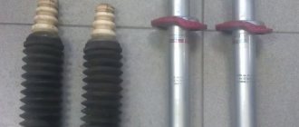
The spring that stands on the telescopic stand should not have cracks.
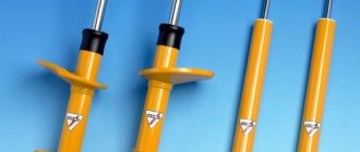
If this is noticed, then the strut needs to be removed and the spring replaced. When replacing one strut on a car, it is better to replace the other as well. Over time, they wear out evenly, and the different stiffness of the struts (the right side is soft, and the left side is hard) do not handle impacts equally, which contributes to a rapid failure.
Troubleshooting
Deformation of the suspension elements, especially body braces, disorganizes the wheel angles and makes it impossible to adjust the camber and toe. First of all, you should check the car's silent blocks, rubber cushions, ball joints, and the shrinkage of telescopic struts.
Repairing a VAZ-2109 requires replacing rubber cushions and silent blocks if there is rupture and one-sided swelling, including after trimming the end surfaces of rubber elements.
You can check the condition of the front suspension ball joint on the car after removing the wheel, by measuring the distance between the lower arm and the disc element of the brake system. If, after pumping the unit, the distance increases from 0.8 mm or more, the hinge should be replaced.
How to change the front struts of a VAZ 2114, VAZ 2115
There are two options for dismantling the shock absorber strut: one allows you to avoid subsequent adjustment of the steering wheel alignment angles, the second allows you to quickly complete the work with more compact units, but after that it is necessary to adjust the steering wheel alignment angles. The difference is that in the first version we remove the strut together with the steering knuckle, without loosening the nuts of the lower and upper (adjusting) bolts securing the strut to the steering knuckle. In this case, the amount of work is greater: we additionally disconnect the brake caliper and ball joint.
In the second option, pay attention! Immediately after replacing the struts, the vehicle requires mandatory wheel alignment adjustment.
We proceed according to the first option, disconnect the steering rod, remove the brake pad guide with the caliper and the brake disc, and remove the outer CV joint from the hub.
Parts and components of the front suspension of the OKA VAZ 1111 car
The VAZ car under the symbol 1111 with the name Oka is a subcompact type of compact city vehicle.
Due to its size, this vehicle is one of the most successful solutions for driving in modern big cities.
The general design of the VAZ 1111 is made using standard technology, independent front suspension, transverse rear beam and front-wheel drive.
The Oka car has an independent front suspension of the MacPherson type. This assumes the presence of a shock absorber strut, which is contained in the steering mechanism. The VAZ 1111 suspension consists of several units:
- two steering knuckles and hub mechanisms with bearings;
- two shock-absorbing struts;
- two lower transverse levers with silent blocks and ball joints;
- two lower longitudinal levers with conical bushings;
- steering rack with rods and steering tips;
- stabilizer bar;
- axle shafts with CV joint mechanism;
- stretcher.
Each of these units carries a different functional load, complementing each other in operation, which explains the good reliability of the VAZ 1111 suspension.
A more complete picture of the work can be presented by breaking it down into individual units. This will give you an understanding of what the Oka car is like as a whole and its front suspension.
Front shock absorbers
The strut with shock absorbers is the most heavily loaded unit. It is entrusted with the functions of monitoring the adhesion of the wheels to the road surface and participating in the control of the vehicle. The Oka is a fairly light machine, so the serviceability of this unit plays a very important role.
The strut is a hollow glass with a knuckle attached to the knuckle of the hub mechanism, into which the shock absorber liner is inserted and secured with a lock nut.
To impart rigidity, it is provided with a support platform for a spring, which gives the Oka machine the necessary vertical stability parameter.
The strut is attached to the car body using a support platform that contains a bearing called a thrust bearing.
This bearing allows the shock absorber to turn after the wheels and at the same time dampens the angle of inclination of the body to the rigid rod.
The lower part of the mechanism is secured to the steering knuckle with two bolts, one of which adjusts the camber angle of the wheel.
Thanks to this design, the stand with a shock-absorbing insert for the VAZ 1111 is very simple, reliable and extremely functional.
Lower control arms, stabilizer bar and steering rack
The purpose of the transverse lower arms is to hold the chassis mechanism in a vertical, stable position. They are attached at one end to the hub and the other to the subframe. It is attached to the steering knuckle through a ball joint; it is designed to rotate the hub. The ball joint is one of the most quickly failing parts of an Oka car.
The silent blocks pressed into them give the levers a small stroke along the axis of attachment to the subframe. They provide the necessary vertical play of the entire chassis, which ensures a stable position of the car on the road.
The longitudinal lower arms are necessary to hold the chassis in the longitudinal plane. They are attached with one side to the transverse arms, and the other to the subframe.
With the help of conical bushings located at both ends of the arms, the chassis of the Oka car provides the necessary longitudinal play.
The tapered bushings of this unit are quite reliable due to the insignificant load and they are changed very rarely.
Despite the fact that the chassis is independent, a stabilizer bar is designed to stabilize its functioning. It combines the entire chassis into a coherent mechanism. The stabilizer is held on the front part of the body and on the transverse lower arms. At the mounting points, the stabilizer is equipped with rubber bushings that provide it with the necessary play.
The main turning mechanism of the VAZ 1111 is a steering rack equipped with rods and ends. Steering tips are installed in the fist and are the main connecting link between the steering wheel and the wheels of the car.
Steering knuckle, hub and CV joint axle shafts
The steering knuckle is the center of the front chassis, to which all other parts are connected. It does not have any moving parts in its design, except for the wheel bearing pressed into it.
This bearing ensures rotation of the hub with the wheel on. The rotational force of the hub is transmitted by an axle shaft with a CV joint mechanism at both ends.
The axle shaft is driven by a gearbox and is equipped with a CV joint, which makes it possible to turn the wheels of the car while driving.
Repair manual for the suspension of a Lada 2113 car, eliminating noise and knocking in the suspension of a Lada 2114, replacing the strut of a VAZ 2113, VAZ 2115, VAZ 2114. Checking and repairing the chassis of a VAZ 2115 with your own hands. Description of the running gear of fret 2113. Operation of the front and rear suspension of fret 2114.
The front suspension of the Lada Samara 2 is independent, telescopic, with hydraulic shock absorber struts, coil springs, lower wishbones with braces and a stabilizer bar.
VAZ 2115 front suspension assembly: 1 – upper support of the telescopic strut; 2 – upper support cup; 3 – compression stroke buffer with protective casing; 4 – compression buffer support; 5 – suspension spring; 6 – lower spring support cup; 7 – steering rod ball joint; 8 – steering knuckle; 9 – telescopic stand; 10 – eccentric washer; 11 – adjusting bolt; 12 – rack bracket; 13 – steering knuckle; 14 – front brake protective cover; 15 – brake disc; 16 – retaining ring; 17 – wheel hub nut; 18 – splined shank of the wheel drive hinge housing; 19 – guide pin; 20 – wheel hub bearing; 21 – ball joint; 22 – suspension arm; 23 – adjusting washers; 24 – stabilizer strut; 25 – stabilizer bar; 26 – stabilizer bar cushion; 27 – stabilizer bar mounting bracket; 28 – body bracket for mounting the suspension arm; 29 – suspension arm extension; 30 – bracket for fastening the extension; 31 – protective cover of the ball pin; 32 – ball pin bearing; 33 – ball pin; 34 – ball pin body; 35 – suspension strut rod; 36 – outer body of the upper support; 37 – inner body of the upper support; 38 – upper support bearing; 39 – rubber element of the upper support; 40 – travel limiter of the upper support; 41 – protective cap of the upper support; B - zone for monitoring the suspension joint
The main element of the suspension of the VAZ 2114, VAZ 2115, VAZ 2113 is a telescopic, hydraulic shock absorber strut 9, the lower part of which is connected to the steering knuckle 13 with two bolts. The upper bolt 11, passing through the oval hole of the strut bracket, has an eccentric collar and an eccentric washer 10. When the upper bolt is turned, the camber of the front wheels changes. The following are installed on the telescopic rack: a coil spring 5, a polyurethane foam buffer 3 compression strokes, as well as the upper support 1 of the rack assembled with a bearing 38.
Telescopic strut VAZ 2114: 1 – compression valve body; 2 – compression valve discs; 3 – throttle disk of the compression valve; 4 – compression valve plate; 5 – compression valve spring; 6 – compression valve cage; 7 – recoil valve nut; 8 – recoil valve spring; 9 – recoil valve plate; 10 – recoil valve disc; 11 – throttle disk of the recoil valve; 12 – piston; 13 – bypass valve plate; 14 – bypass valve spring; 15 – plunger; 16 – plunger spring; 17 – rod guide bushing with a fluoroplastic layer; 18 – guide bushing cage; 19 – sealing ring of the rack housing; 20 – rod seal; 21 – oil seal cage; 22 – gasket of the rod protective ring; 23 – rod protective ring; 24 – nut of the strut body; 25 – compression buffer support; 26 – rod; 27 – spring cup; 28 – rotary lever; 29 – rod limit sleeve; 30 – rack body; 31 – cylinder; 32 – drain tube
The upper support of the VAZ 2113 is attached with three self-locking nuts to the body mudguard strut. Due to its elasticity, the support ensures that the strut “swings” during suspension movements and dampens high-frequency vibrations. A bearing built into it allows the rack to turn along with the steered wheels. Parts of a telescopic hydraulic shock absorber are mounted in the strut housing. A hydraulic recoil stroke buffer is installed in the upper part of the cylinder, consisting of a plunger 15 and a spring 16. It limits the movement of the rod during the recoil stroke. The lower part of the steering knuckle 13 is connected by a ball joint 21 to the wishbone 22 of the suspension. Braking and traction forces are perceived by longitudinal braces 29, which are connected through rubber-metal hinges to transverse arms 22 and brackets 30. At the junction of the brace with the lever of the VAZ 2113, VAZ 2114, VAZ 2115 and the bracket, adjusting washers 23 are installed, which adjust the angle of the longitudinal inclination of the axis turn. A double-row angular contact bearing 20 of a closed type is mounted in the steering knuckle, on the inner rings of which the wheel hub is mounted with interference. The bearing is tightened with a nut 17 on the shank 18 of the outer wheel drive joint housing and is not adjustable. All front and rear wheel hub nuts are the same and have right-hand threads. The anti-roll bar is a bar 25, the knees of which are connected to the transverse arms 22 of the suspension through drains 24 with rubber and rubber-metal hinges. The middle (torsion) part of the rod is attached to the body with brackets 27 through rubber pads.