Most owners of a Lada 4×4 (Niva) car are thinking about how to improve the factory characteristics of the model, and one of the most popular procedures for tuning a car is installing an additional fan.
In case of frequent off-road trips, the car engine is subjected to strong heating, which standard equipment cannot cope with; the same thing happens during long-term use during the hot season, especially in the southern regions.
If the engine overheats, repairs will be quite expensive, and an additional cooling fan will help avoid this risk. After installing this element, the Niva can be used in the harshest conditions without fear that the internal combustion engine will “boil”.
Selecting an additional fan
An important point before installation is the choice of the devices themselves that can be installed on the car. Both factory-made dual fans and foreign-made single fans are suitable for the Niva.
Factory models require less effort during installation, since they have appropriate fastenings and are relatively inexpensive; Foreign-made analogues are of higher quality and quieter, but their price is higher even if you purchase a used spare part.
If you install an electric fan on a car, this can be done both from the inside of the radiator and from the outside. In the first case, a device of suitable dimensions and power is purchased from cars of the Volzhsky plant, in the second - VAZ-21214 electric fans.
External parts must be protected from frost in winter to prevent the impeller from freezing to the inside of the casing, and the internal location requires sufficient free space under the hood.
The second location option is more common.
Possible problems and their causes
Like any vehicle system, the cooling circuit must be regularly monitored and worn parts replaced. The first indicator of possible problems will be the level of coolant in the expansion tank. The main breakdowns of the cooling systems of VAZ Niva models:
- Maximum engine heating with cold main radiator pipes means the thermostat is broken. The part cannot be repaired, only replaced.
- Electric fans in injection systems turn on uncontrollably or do not start at all. This is an indicator of a breakdown of the sensor that transmits data to the controller.
- A faulty sensor on the cylinder head causes incorrect data on the control panel or its complete absence.
- A constant decrease in antifreeze level indicates a leak somewhere in the circuit.
Preparing for installation
Before you start installing the element, there are a few things to consider:
- Before installation, you will need to remove the radiator, regardless of the location of the additional fan, since it will interfere;
- To work, you will need to purchase a tee from a GAZelle car, and you can find several options for this device on the market. A short tee is not suitable due to the small size and diameter of the pipes; a long tee will have to be shortened. The most sensible solution is to find the middle tee;
- when choosing a temperature sensor, the TM-108 model is suitable (it is also installed on VAZ-03, 07, GAZ-3102, 3110). Before installation, the sensor thread is lubricated with a sealing agent: the standard washer does not provide complete protection against leaks.
How to install an additional fan on a Niva: step-by-step guide
To install an additional fan on the 2121 or 21213 model, you will need to perform the following steps:
- draining the antifreeze, removing the radiator grille and the device itself. The main difficulties at this stage are the souring of the screws and threads, which is why it can be torn off when twisting. If this happens, the screws will have to be drilled out;
- After removal, it is necessary to make steel brackets 2.5 cm wide with threaded holes: they are necessary to fix the fan casing to the body. A pair of products is placed to the left of the radiator, another pair is placed above and below. On later modifications of the Niva, mounts for installing electric fans are already available from the factory: for such a model you will need to remove the grille and deflector of the standard unit;
- the upper brackets require the installation of a seal for tightness; You can use products installed on car doors. After this, you can mount the fan itself and secure it in the casing. In some cases, the body does not have fixation points for the device, and welding will be required to create the fasteners.
Boring the block does not affect the gasket; there is no need to modify it. The order in which the cylinder head bolts are tightened is important. It is failure to comply with this rule that most often leads to damage to the gasket during the assembly process.
There are cases of rupture of jumpers, not to mention the violation of tightness due to pinching of the gasket.
Installed dual fan
After this, the device is connected to the car's electrical system. Since it will turn on automatically, you will need to install a temperature sensor, which will signal the need to cool the internal combustion engine.
The factory radiator usually has a hole for installing such a sensor, but if it is not there, you can insert a tee from a GAZelle with the appropriate thread.
When installing the wiring, you will need to install a fuse with a relay (if the device is dual, two of these elements are needed) and install a power button in the cabin.
The classic operating diagram of an electrical appliance can be improved: three positions (device off, automatic and forced, i.e. manual start) will ensure the correct temperature regime for the engine in any operating conditions.
Electric engine cooling fan with casing for VAZ Niva
Dear customers, in order to avoid errors when sending the electric fan assembly with casing VAZ 21214 NIVA, in the “Comment” line indicate the injection or carburetor engine, your car model, year of manufacture.
On a fuel-injected NIVA 4x4 car, if the air flow is not intense enough, the radiator is cooled by an electric fan 21214-1300024. It is installed in front of the engine radiator and is activated by a signal from the electronic engine control unit.
The main radiator of the NIVA 4x4 car is a cellular heat exchanger operating on the coolant-air principle. Its main purpose is to release excess heat from the engine to the environment. Equipped with two electric fans installed in a special diffuser on the heat exchange surface of the radiator, and a temperature sensor. The latter signals an increase in temperature in the heat exchanger cells, as a result of which the control unit turns on the fan. Most often, this situation occurs when driving in traffic jams or increased loads at low speeds.
On injection vehicles VAZ 2121, VAZ 21213-21214i, cooling system fans 21214-1300024-43 “Valee 95” are driven by DC electric motors excited by permanent magnets. The operation of the fans is controlled by the engine management system controller, which receives a signal from the coolant temperature sensor (coolant temperature sensor). The electric motors of the engine cooling system fans do not require maintenance. If it fails, replace the engine cooling fan with a new one.
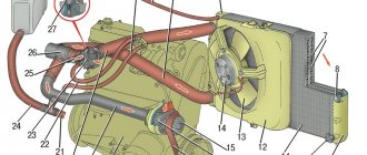
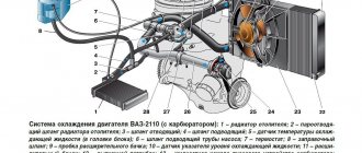
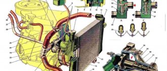
1 – expansion tank; 2 – expansion tank plug; 3 – pipe for draining fluid from the heater radiator; 4 – hose for draining fluid from the heater radiator; 5 – heater valve; 6 – heater radiator; 7 – hose for supplying fluid to the heater radiator; 8 – hose for supplying fluid to the carburetor heating block; 9 – hose for draining fluid from the carburetor heating unit; 10 – thermal vacuum switch of the recirculation valve; 11 – thermostat bypass hose; 12 – coolant pump cover; 13 – fan impeller; 14 – coolant temperature sensor for the instrument cluster; 15 – radiator supply hose; 16 – radiator; 17 – radiator cap; 18 – radiator drain plug; 19 – fan casing; 20 – radiator outlet hose; 21 – coolant pump drive belt; 22 – coolant pump housing; 23 – hose for supplying coolant to the pump; 24 – thermostat; 25 – coolant supply hose to the throttle body; 26 – coolant drain hose from the throttle body; 27 – coolant temperature sensor for the injection system; 28 – electric fan impeller; 29 – electric motor; 30 – electric fan casing.
The VAZ 21214 engine cooling system is liquid, closed type with forced circulation of coolant and an expansion tank.
Technical characteristics of electric fans of the engine cooling system with casing 21214-1300024-43:
— Voltage consumption: 12V;
— Current consumption: 18A;
— Number of electric fans — 2 pcs.;
— Impeller Ø: 285 mm;
— Speed: 2,700 rpm;
— Type of rotation: axial.
The cooling system is liquid, closed type, with forced circulation. The tightness of the system is ensured by valves in the expansion tank plug. The inlet valve is normally open (the gap between it and the rubber gasket is 0.5–1.1 mm) - in this case, the system communicates with the expansion tank. When the engine heats up, the liquid expands and is forced into the tank; when it cools, it returns back. The inlet valve closes when there is a sharp increase in pressure in the system (boiling liquid), while the outlet valve is also closed. It opens when the pressure in the system reaches approximately 0.5 kgf/cm2, which increases the boiling point of the liquid and reduces its losses. The thermal operating conditions of the engine are maintained by a thermostat and a radiator fan. On an engine equipped with an injection system, two electric fans are installed in front of the radiator and are activated by command from the electronic engine control unit.
On a carburetor engine, the fan is mechanically driven and mounted on the coolant pump pulley.
The VAZ 21213 coolant pump is a vane, centrifugal type, driven from the crankshaft pulley by a V-belt. The pump housing is aluminum. The roller rotates in a double-row bearing with a lifetime supply of lubricant. The outer ring of the bearing is locked with a screw. A pulley hub is pressed onto the front end of the roller, and a plastic impeller is pressed onto the rear end. For the correct position of the pump pulley groove, the distance from the mating surface of the pump cover to the outer end of the hub must be 84.4 ± 0.1 mm. When installing the cover with the gasket, check the gap of 0.9–1.3 mm between the impeller blades and the pump housing. To do this, you can use plasticine rollers: they are placed on equidistant impeller blades, a cover is installed, the nuts securing it are tightened, then the cover is removed and the remaining thickness of the plasticine is measured - it is equal to the gap.
Axial and radial play in the pump bearing that can be felt by hand is not allowed. If the bearing or self-pressing seal of the pump fails, it is recommended to replace the pump cover complete with the roller and impeller.
The redistribution of liquid flows is controlled by a thermostat with a solid heat-sensitive element. On a cold engine, the thermostat valve closes the pipe leading to the radiator, and the liquid circulates only in a small circle (through the thermostat bypass pipe), bypassing the radiator. The small circle includes the heater radiator, intake manifold, carburetor heating unit (on engine 21213) or throttle assembly (on engine 21214). At a temperature of 78–85°C, the valve begins to move, opening the main pipe; in this case, part of the liquid circulates in a large circle through the radiator. At a temperature of about 90°C, the main valve opens completely, and the bypass valve closes, and all the liquid circulates through the engine radiator. The main valve stroke must be at least 6.0 mm.
You can evaluate the serviceability of the thermostat by heating the lower radiator pipe: it should be cold until the liquid temperature (according to the indicator) reaches 80–85°C, and hot when it rises to 85–90°C. The thermostat is beyond repair. In case of malfunction, loss of tightness, or deformation of the pipes, it is replaced.
The radiator consists of two vertical plastic tanks (the left one has a baffle) and two horizontal rows of round aluminum tubes with pressed-on cooling plates. To increase cooling efficiency, the plates are stamped with a notch. The tubes are connected to the tanks through a rubber gasket. The liquid is supplied through the upper pipe and discharged through the lower. There is a coolant drain plug at the bottom of the left reservoir.
For better cooling of the radiator, there are casings that direct air flow from the fans. On the 21214 engine, electric fans rotate in a casing in front of the radiator.
On the 21213 engine, the main fan shroud consists of two halves (lower and upper), the lower half has a rubber seal on the radiator side. An additional guide casing is installed in front of the radiator.
The expansion tank is made of translucent polyethylene, which allows you to visually monitor the fluid level (3–5 cm above the “MIN” mark on a cold engine).
An additional temperature sensor is installed in the exhaust pipe of the 21214 engine, which provides information to the electronic engine control unit.
The engine cooling system uses special fluids based on a mixture of water and ethylene glycol. They have a low freezing point and a high boiling point. In addition, thanks to the complex of added additives, the coolant prevents corrosion of the channel walls, does not foam, and extends the service life of the coolant pump seal.
The engine cooling jacket is a system of channels in the block and cylinder head that allows heat to be removed from the hot walls of the liners and combustion chambers.
The design of the electric motor does not imply maintainability. The electric motor has a service life of more than 5,000 hours, which is equivalent to approximately 8 years of average operation. Spark suppression chokes are needed in order to “extinguish” the spark that occurs when the contact of the brushes with the commutator breaks, due to which the brushes and commutator quickly wear out (burn out).
Cooling fan 21214-1300024-43 “Valee 95” fully complies with the requirements of the manufacturer’s standards:
— aerodynamic properties;
— electrical parameters.
Products are certified according to the international quality management system ISO 9001 TUV and have GOST-R certificates of conformity.
Other article numbers of the product and its analogues in catalogues: 21214130002443.
VAZ 2121, VAZ 21213-21214i
Any breakdown is not the end of the world, but a completely solvable problem!
How to independently replace the VAZ-21214 radiator motor in Sat. with a casing on an injection car of the NIVA 4x4 family.
AvtoAzbuka online store, repair costs will be minimal.
Just COMPARE and BE SURE!!!
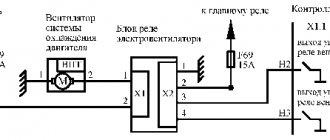
Connection diagram of the electric fan to the system
Features of installation in front of the radiator: The process of installing an additional fan according to this scheme differs little: it is necessary to provide appropriate fastenings and make sure that the mounting bolts do not interfere with the installation of the device. In order for the air flow to be directed inside, you will need to install an inlet diffuser: it can be welded from steel plates. This method of installing an additional cooling device is especially popular among those Niva owners who drive mainly in the city.
Installing an additional electric fan, whether a dual or single model, allows you to cool the Niva engine at increased speeds, as well as at high air temperatures, which cause the system to overheat during road driving conditions.
The electrical device has a high rotation speed, due to which it blows the engine more efficiently and reduces the risk of damage. To install such a device, you will need a relatively small set of tools, and the task can be completed in 1.5-2 hours.
Methods for connecting fans.
The temperature rose, the fans turned on, everything was simple. Pull the wire back together with the bundle.
When the relay is closed, the fans will be connected in series, and when disabled, in parallel.
Compiled from the experience of installing them in 2 cars. After this, connect the free terminals on the motors with a wire of the appropriate cross-section.
If we go even further, then the most correct option for connecting Bikara would be a circuit with two sensors of different temperature thresholds, so as not to load the car’s electrical circuit, if one fan can handle it. APS status indicator. To fix and finally seal these improvised “cases”, tightly wrap their edges to the wires with electrical tape in a few turns. Current passes through the inductor, resulting in an electromagnetic field.
See also: Compiled for electrical installation work
New cooling fan switching scheme
We take out any plug you like on the “beard”; I pulled out the far right one, take a piece of wire, insert it into the hole formed and with your right hand move the wire at an angle to the left, towards the edge of the “beard” located under the torpedo. Windshield wiper motor. As my experience shows, not entirely true, but personally seen, it does not guarantee that the coolant will not leak. Whoever has these supply pipes laid, pull out the rings.
This is caused by the engine working under heavy loads when driving off-road. Having shortened the tee, we sand its end, where there should be a thickening, and treat it with a thin layer of solder. Starter There is no great need for them. And it’s very simple.