Why do you need a guide bushing?
The guide bushing can quite rightly be considered the main element on which the resource and proper operation of the “seat - valve plate” tandem depends. The material from which the part is made and its design itself are primarily aimed at working under conditions of high speeds of the valve stem fixed in it, constant high-temperature loads and the almost complete absence of lubrication in the valve-bushing pair.
Causes and consequences of deformation
The described conditions lead to the fact that during engine operation, the valve guide bushing also wears out, which is why, over time, its alignment with the valve stem may be disrupted. Subsequently, the part breaks even more and the valve begins to “walk” and does not fit tightly to its seat, and this, in turn, leads to the chamfer of the seat breaking over time. As a consequence, you can get a burnout of the valve and have to replace the seat.
Appearance of bronze guide bushings for VAZ 2108–2109 models
Also, due to the “walking” of the valve in a broken guide, the oil seals can quickly become unusable. They simply will not be able to hold oil with increased angular displacement of the valve stem. The result will be oil getting into the engine, and if you also take into account that more oil will pass through the broken bushing than usual, then the situation will not be pleasant. Carbon deposits on valves and other parts around the combustion chamber will increase, the level of harmful exhaust emissions will increase, and you may end up with a prematurely failed catalytic converter. And simply replacing the valve stem seals is not enough, as the problem will soon return again.
Why you shouldn't neglect checking
When repairing an engine, it is better to pay special attention to its head. Often it is this part of the engine that is to blame for the fact that the level of compression in the cylinders is far from the desired level. When repairing cylinder heads, motorists sometimes limit themselves to only grinding the valves to their seats, believing that there is nothing particularly wearable in all-metal bushings. At the same time, checking how large the gap between the part and its valve is will be completely worthwhile. When the obtained clearance figures go beyond those recommended by the car manufacturer, then no amount of grinding in the valves or replacing the valve stem seals will protect against problems in the future.
Materials used to make bushings
For the manufacture of bushings, materials with good wear resistance and thermal conductivity are used. Among these you can find:
- special cast iron alloys;
- bronze;
- brass;
- metal ceramics.
In terms of thermal conductivity and cost, brass, along with bronze, are among the leaders, so the vast majority of bushings are made from alloys of these metals.
Nuances to consider
Most bushings have a special support collar on the outside, designed to ensure proper fixation of the part vertically in the cylinder head. If the part is smooth, then installation is carried out using a special mandrel.
For intake valves, the guide bushings should not protrude so as not to increase the aerodynamic drag of the intake channel. Exhaust valve bushings are designed to “hide” the valve stem as much as possible to protect the latter from high temperatures and better heat dissipation.
Appearance and location of the valve guide in the cylinder head
We recommend: Why don't the gears shift when the engine is running?
The manufacturing precision of the bushings is very high. This is necessary to obtain the most accurate alignment and the best fit of the valve plate and seat during engine operation. The outside of the body of the part that is to be pressed into the cylinder head must be processed as cleanly as possible; there should be no scratches or marks on it. This ensures optimal heat removal from this accessory to the block head.
Replacement process
As mentioned above, a special attachment is required to remove and install the guides. Let's look at what it is and how to use it.
Description of the tutorial
The mandrel for removing and installing the guide consists of two parts. The first part is a rod of a certain length, machined on a lathe and having different diameters in certain places. The largest diameter of the rod occupies its main length and is 18 mm. The rod is held by hand by this part, and it limits the rod from slipping to the other side when removing the bushing, which will protect the surface of the block head from being hit with a hammer. The diameter of the second part of the rod is equal to the diameter of the sleeve. The length of this part is equal to the depth of the hole in which the sleeve is located. The third part of the stem is the shortest - its diameter corresponds to the internal diameter of the valve stem (the diameter of the inner surface of the guide). Its purpose is to ensure that when knocking out the bushing, the direction of the rod strictly corresponds to the direction of the bushing and does not create a distortion of the rod when hitting it with a hammer.
The second part of the rod is similar to a socket head. It is distinguished from a socket head by the absence of edges inside (a cylindrical hole with a diameter and length equal to the diameter and length of the upper part of the guide). In the upper part of the head there is a hole with a diameter equal to the inner diameter of the sleeve and the outer size of the rod on the working side. As can be seen from the description of the mandrel, finding a replacement for it using available materials is not so difficult. To do this, at a minimum, you will need a cylindrical rod of a convenient length, the diameter of which on one side is equal to the outer diameter of the sleeve. As an attachment, you can use an old oil pump rod from a VAZ, after grinding off the gear.
To install the guide in place, use a socket of the appropriate diameter or a suitable hollow tube. Further in the text the terms “mandrel”, “rod”, “head” will be used, implying both a special mandrel and suitable available means.
The process of removing a worn guide and installing a new one
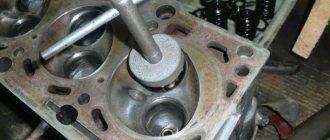
To remove the bushing, turn the cylinder head over with the working part facing up. Next, take the stem, insert it into the valve hole and carefully press it out with a hammer.
In this process, the accuracy of the blow is important. If you hit the surface of the cylinder head with a hammer, this will disrupt the plane of the cylinder head. To knock out the bushing, the blow must be strong, and for this it is better to use a heavy hammer. To install a new bushing, place the cylinder head on the surface in the position in which it is placed on the engine. Then take the new bushing, coat the outer surface with oil and install it in the desired hole.
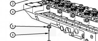
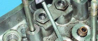
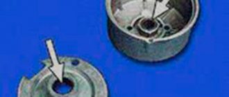
Next, put the head on it and insert the rod. Gently hitting the top of the rod with a hammer, press the bushing guide into place. When installing, pay attention that the selected means do not touch the top of the oil seal seat (marked with arrow 1), since upon impact the seat will be deformed or a piece will break off from it. The head should rest against the base of the oil seal seat (marked with arrow 2).
There are no problems with removing and installing the guide bushing. This is a simple procedure that requires certain knowledge, accuracy and precision when working.
Something else useful for you:
During operation, valve bushings wear out, mainly in the plane of rotation of the camshaft, and the alignment of the bushing with the valve is lost, the bushing breaks at the ends in this plane. Then the valve begins to wander - its beating exceeds the norm, because of this it does not fit tightly to the seat, and accordingly it breaks the chamfer of the seat. This can lead to burnout of the valve and subsequent replacement of the seat. Or maybe it won’t, if it’s corrected in time.
In a worn guide, the valve will move crookedly, which will lead to rapid wear of the oil seals, then oil will easily get into the engine, especially since the bushing itself is broken, and more oil will pass through it. Simply replacing the caps will not help; the new ones will quickly wear out and everything will start all over again.
Oil can also escape through the gap between the bushing and the head, especially if you install a “proprietary” crooked bushing, it seems that the MSK is fine, they don’t let it through, and the valve moves without distortions, but still everything is covered in oil. And this breakdown is quite difficult to diagnose, because you can’t look into it, but there will still be oil on all sides.
Causes of parts failure and their consequences
A characteristic feature of the guide elements is that they do not fail at once, but wear out gradually. The lifespan of parts on budget cars ranges from 180 to 300 thousand km, and on more expensive foreign cars it can reach 1 million km. The wear process is influenced by several factors that can accelerate it:
- the quality of the motor oil used and the timeliness of its replacement;
- temperature conditions of the power unit, the more often the engine overheats, the faster the rubbing surfaces wear out;
- the quality of the fuel and combustible mixture, whose vapors penetrate into any leaks and contribute to the process of slow destruction of parts.
Carbon deposits on the rod destroy the bushing quite quickly
Note. The working life of all elements of the gas distribution mechanism is also affected by the serviceability of the power supply and ignition system. When, as a result of a malfunction, pops occur in the fuel or exhaust manifold, the lubricant between the valve-bushing pair is washed off with unburned gasoline, which is why the mechanism runs “dry” for several seconds.
A worn part is characterized by a “broken” internal hole, as a result of which the valve stem begins to move too freely in it, and then play appears. The rod warps during operation, and the plate does not fit well with the seat, the tightness of the interface is gradually lost. Gases escape from the combustion chamber into the mechanism, and oil enters from above, resulting in the formation of carbon deposits. It also accelerates wear, quickly rendering the part completely unusable.
Why can cartridges fail?
The main reason for failure of guide bushings is their wear. As a result, the consumption of lubricating fluid increases, since the backlash of parts leads to rapid failure of the valve stem seal and oil leaks into the combustion chamber. As a result, there is the formation of carbon deposits, a violation of the temperature regime of the engine, an increase in the toxicity of exhaust gases and breakdown of the catalyst (if the car has one).
Timely replacement of engine oil and proper operation of the vehicle’s internal combustion engine allows you to extend the life of the bushings and change them every 180–200 thousand kilometers. However, due to valve clearances and engine oil non-compliance with recommended standards, lateral wear of the bushings and a decrease in valve mobility along the axis of the rod may occur due to an increase in the radial load on it. For this reason, after changing the valve stem seals, the gap in the guide bushings must be adjusted. If the gap is too large and play is detected, the bushings must be changed.
Tools and materials
Replacement of guide bushings is carried out using the following tools:
- hammer;
- sweeps at 8.022 and 8.028;
- mandrel for pressing out and pressing in bushings.
The bushings are changed using a stepped mandrel - a brass or bronze tool. It rests against the guide sleeve, after which it is knocked out with a hammer blow. This method of pressing out does not harm the cylinder head as much as using a regular hammer and chisel. A special puller is used not only to remove bushings, but also to replace them.
Stepped mandrel used for pressing out VAZ 2106 guide bushings
The best tool for replacing guide bushings is a push-out puller. Such devices allow you to remove valve bushings without damaging the seating plane on the cylinder head. The presence of this tool allows you to avoid scoring and other cylinder head defects that may appear when using a mandrel and hammer.
Puller-extruder for guide bushings VAZ 2106 - universal tool
General arrangement of cylinder head bushings
On modern cars, valve heads are made of special alloys.
Valve guides for VAZ 2106
On the VAZ 2109, for example, the guides are made of wear-resistant material and are pressed into the head at high temperatures, so changing them is quite difficult. But it is still necessary to carry out the replacement procedure, since the bushing, despite its strength, wears out over time, losing its tightness. The problem is especially acute for engines with a large number of valves.
Reasons for replacing VAZ-2109 valve guides
Among the reasons that lead to replacing the valve guide element of the VAZ-2109 engine, experts cite wear of this part. It can be determined by the following characteristics:
- Engine oil entering directly into the combustion chamber (this can be judged by increased oil consumption and gray smoke from the exhaust pipe).
- Tapping from the side of the engine block head (this is the bushing and valve knocking against each other).
- Reduced car engine power.
Also, a malfunction of the guide element can be noticed visually when replacing a set of valves and during a major overhaul of the engine block head.
As soon as the car owner notices signs indicating failure of the guide elements, without wasting time, they should be replaced with new ones. This can be done either independently in a garage or with the help of qualified car service specialists.
We recommend: When should you change the fuel filter on a Renault Logan?
Wear detection
The nature of the operation of the valve stem-bushing pair causes increased wear on the inner surface of the latter. It becomes noticeable when the vehicle is driven for a long time (about 150 thousand km). At the same time, the use of low quality oils can significantly speed up the life of the bushings. Therefore, it is always advisable to determine the degree of wear before replacing them. There are two methods for this:
Set of bore gauge and micrometer for determining bushing wear
Bore gauge with dial indicator for measuring clearances between the bushing and the valve
Replacing valve guides
Extraction
- Here it is strongly recommended to warm up the cylinder head to about 100 degrees Celsius before the procedure. The aluminum from which the cylinder head is made has a higher expansion coefficient than the material of the guide sleeve. Due to heating, the tension of the bushing-cylinder head connection is significantly reduced and the guides can be easily pressed out without damaging the seat with light blows of a hammer or sledgehammer.
- A special drift tool (mandrel) is used for extraction. Despite its highly specialized nature and high cost, this tool makes it possible to press out exactly along the axis of the guide sleeve. For such procedures, experienced car mechanics often acquire pneumatic hammers and special drift attachments for them.
Tool for pressing out and pressing in guide bushings
- It happens that a part does not want to come out. In such cases, it is drilled out. And it’s better to use a drilling machine. If you use a conventional drill for work, there is a risk of damaging the socket and creating a misalignment. You may not have to completely drill it out. With thin walls it will be much easier to knock it out.
- The inner surface of the seat after removal should be as smooth as possible and perfectly clean. There should be no scratches, roughness or other, even the slightest, defects. To obtain a similar result, it must be further processed after pressing.
Installing new
- Before installing new spare parts, you need to determine the value of the actual tension. To do this, the diameter of the seat in the cylinder head and the diameter of the bushing are measured. The difference between the first and second should not exceed 0.03–0.05 mm.
- If the socket is noticeably larger than the bushing chosen for it, then you should look for a part with a larger diameter. If the diameter of the socket is insufficient, then you can use the services of a drilling machine to increase it.
- Before pressing in new bushings, the cylinder head must also be heated. But it is generally recommended to cool new spare parts in liquid nitrogen, which will greatly reduce their outer diameter and make it easier to enter into the housings that have expanded from heating, and will also reduce the risk of damage during pressing.
- But since not everyone has liquid nitrogen in their garage, you can first place the new bushings in the freezer. Again, if the latter is available in the accessibility zone. For simplicity, we can take as the required temperature difference between the cylinder head and the guide bushing equal to 150 degrees Celsius. Even when pressing bushings, it is recommended to lubricate the rubbing surfaces with liquid machine oil, especially if the parts have not been heated/cooled.
- The pressing process itself follows the same scenario as pressing out. As a tool, a mandrel and a hammer (or an air hammer with an attachment). Next, using a series of successive blows, we hammer the part into the seat.
Final stage - development
It happens that when installing valves, they do not fit into the new bushings. This is due to the fact that when pressed in, the guides may slightly change their internal diameter. This is where reamers come to the rescue, with which our spare part is bored to the required diameter. We apply sequentially one after another in an increasing manner. At the same time, measurements are taken after each use. It is better to take diamond reamers straight away, since steel ones deteriorate much faster.
Reaming guide bushings 8.022 mm
As mentioned at the very beginning, valve guides, despite their apparent simplicity, are one of the basic elements of the gas distribution mechanism. Understanding this point, as well as the possible consequences in the event of a malfunction, will save a lot of nerves, time and money.
Source
Why are guide bushings needed?
At the beginning and middle of the last century, car cylinder heads were made of cast iron, and the valves were simply inserted into precisely drilled holes. But subsequently, manufacturers abandoned cast iron heads due to their heavy weight and insufficient removal of excess heat, and they were replaced by lightweight cylinder heads made of aluminum alloys. These metals have excellent thermal conductivity, but have little resistance to wear from friction.
To solve the problem, a guide sleeve was invented - an intermediary between the soft alloy of the cylinder head and the steel valve stem, which constantly moves up and down during operation. Made of cast iron or special bronze, it is securely pressed into the cylinder head body, and the valve is inserted inside with minimal clearance.
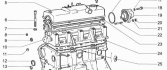
The engine diagram shows the location of the guide bushings
The bushing itself is a hollow cylinder, made exactly to size for a specific car model. The outer surface is polished and smooth to the touch, and the inner surface has a spiral-shaped groove in the form of a thread. Motor oil moves along it, lubricating the valve axis and reducing friction. A shallow recess is made in the upper part of the guide part, into which a retaining ring is inserted.
On the left is the bushing for the exhaust valve, on the right is for the intake valve
Important point. The guide elements for the intake and exhaust groups of valves differ in design, although they may look the same in appearance (for example, parts for Russian VAZ 2108-09 cars). The difference is this: in the bushing for the exhaust tract, the oil groove is made along the entire length of the hole, and for the intake tract - only halfway. But products for the “classic” VAZ 2106 also differ in size; with the same diameter, the exhaust elements are longer than the inlet elements.
Bronze bushings for VAZ 2109 all look the same
We recommend: Independent replacement of the vacuum booster on a VAZ 2114
Bushings perform the following functions:
- as the name implies, they direct the movement of the valve so that its plate is clearly aligned with the seat and fits tightly to it;
- take on the load from the friction force that occurs during the translational and reciprocal movement of the valve stem;
- the valve cup gets very hot in the combustion chamber, and the bushing transfers this heat to the aluminum alloy of the cylinder head;
- Thanks to a special groove, the part provides lubrication of rubbing surfaces.
Cast iron parts of VAZ 2106 - intake bushings are shorter than exhaust bushings
When the element is pressed into the cylinder head hole, its upper part of smaller diameter protrudes several millimeters above the surface. This is necessary to install an oil seal on it (also known as a valve seal), which prevents lubricant from the upper part of the engine from entering the combustion chamber through the inner hole of the bushing.
This is what the protruding part looks like where the oil seal is put on
Cylinder head and valve mechanism of VAZ 2101 Zhiguli
3.11.1 Cylinder head and valve train
Main dimensions of the cylinder head, valves and guide bushings The cylinder head is common to 4 cylinders, cast from duralumin alloy. It is unified, i.e. monotonous for engines 2101, 21011 and 2103. Cast iron seats and guides are pressed into the cylinder head.
3.11.2 Device personalities
Main dimensions of the cylinder head, valves and guide bushings The cylinder head is common to 4 cylinders, cast from duralumin alloy. It is unified, i.e. monotonous for engines 2101, 21011 and 2103. Cast iron seats and guides are pressed into the cylinder head.
3.11.3 Removal and installation on the carriage The cylinder head is removed from the engine on the carriage if the engine itself does not need to be removed to eliminate the malfunction, or if it is only necessary to remove carbon deposits from the surface of the combustion chamber and valves. Removal PERFORMANCE ORDER 1. Drain the coolant from the radiator and the central unit.
3.11.4 Disassembly and assembly
Valve mechanism parts 1 – valve; 2 – retaining ring; 3 – guide sleeve; 4 – oil deflector cap; 5 – support washer of the external spring; 6 – support washer of the internal spring; 7 – internal spring; 8 – external spring; 9 – spring plate; 10 – crackers; eleven - .
3.11.5 Cleaning the cylinder head PERFORMANCE ORDER 1. Place the head on the stand A.60353. 2. Remove carbon deposits from the combustion chambers and from the surface of the exhaust channels with an iron brush driven by an electronic drill. Clean and inspect the inlet channels and oil supply channels to the valve drive levers.
3.11.6 Checking and grinding valve seats
Intake valve seat profile I – new seat; II – seat after repair Exhaust valve seat profile I – new seat; II – seat after repair The shape of the chamfers of the valve seats is shown in Fig. Intake valve seat profile and fig. Saddle profile you.
3.11.7 Valves PERFORMANCE ORDER 1. Remove carbon deposits from the valves. Check if the rod is deformed and if there are any cracks on the plate; If damaged, replace the valve. 2. Check whether the working chamfer is worn or damaged. When grinding the working chamfer of the valve on a grinding machine.
3.11.8 Valve guides
PERFORMANCE ORDER 1. Check the gap between the guide bushings and the valve stem by measuring the diameter of the valve and the hole in the guide bushing. Mounting clearance for the latest bushings: 0.022–0.055 mm for intake valves and 0.029–0.062 mm for exhaust valves; very acceptable .
3.11.9 Oil deflector caps of guide bushings In oil deflector caps, peeling of rubber from the fittings, cracks and excess wear of the working edge are not allowed. When repairing the engine, it is recommended to constantly replace the oil seals with new ones. It is recommended to replace warped oil seals on a removed cylinder head.
3.11.10 Valve levers PERFORMANCE ORDER 1. Check the condition of the working surfaces of the lever mating with the valve stem, with the camshaft cam and with the spherical end of the adjusting bolt. If bumps or hazards occur on these surfaces, replace the lever with a new one. 2. If found.
3.11.11 Springs
Main data for checking the external valve spring Main data for checking the internal valve spring Diagram for checking the lever spring A - size in the free state; B – size under overload PROCEDURE 1. Make sure there is no l.
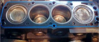
3.11.12 Cylinder head gasket The gasket surfaces must not be damaged. They should be even, without dents, cracks, swelling or kinks. Detachment of the lining material from the reinforcement is not allowed. There should be no cracks, burns or peeling on the edges of the holes.
3.11.13 Checking the tightness of the cylinder head
Checking the tightness of the cylinder head using fixture A.60334 1, 2, 4 – plugs; 3 – device plate; 5 – flange with water supply fitting PERFORMANCE ORDER 1. For hydraulic testing for the tightness of the cooling jacket of the cylinder head: – .
Source: automend.ru
Installation of guide bushings on a VAZ 2109
- Changing guide bushings on a VAZ 2109 begins with fixing the puller to the part using turned nuts. The central part of the tool is held with the upper key, and the guide sleeve is pressed out using the lower one. Its exit from the socket is accompanied by a characteristic click, after which the part is removed.
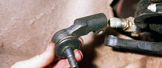
The VAZ 2106 valve guide bushings are pressed out using a puller
- To facilitate the process of installing the bushing, it is treated with engine oil. The part is pressed into the valve seat using a conical bushing. In this case, for the intake and exhaust valves, the bushings are selected in such a way that the thread on the guide part is several centimeters longer.
- It is desirable that the parts have different temperatures: the cylinder head should be heated to 150°C, the bushing, on the contrary, should be cooled. If you do not create a temperature difference, you can provoke deformation of the aluminum alloy, as a result of which too large internal stresses will arise in the metal. This may cause the engine valves to overheat.
- There is a ring on the bushing that determines its correct fit.
After installing the part, a hole is drilled out on it using a special tool. The diameter of the hole can be checked with a bore gauge - it must correspond to the parameter specified in the technical documentation of the car. If the data matches, then install the valve. If the bushing does not fit tightly to the seat, it is straightened using a cutter. Lining the VAZ 2109 valve seats using a cutter - After installing new bushings, gaps may appear in the cylinder head due to loss of alignment. To fix this problem, it is necessary to grind in the valves. For this purpose, the valve seats are once again processed with a roller cutter. The procedure for installing new bushings is completed after the final grinding of the valves.
Cylinder head and valve design
The functioning of the valve mechanism on VAZ 2106 and VAZ 2109 cars depends on the operation of the chain drive (modern car models are equipped with belt drives).
The structure of the cylinder head is quite primitive: these are seats, springs, guide bushings. The valves in the system close automatically using built-in springs. To prevent engine oil from leaking into the combustion chamber, an oil seal is attached to the bushing.
Diagram of the cylinder head of the VAZ 2106
The valve mechanism operates in difficult conditions with high temperatures and oil starvation. Its main task is to ensure the tightness of the entire system. Problems in its operation can cause a decrease in power, increased fuel consumption and rapid wear of the timing belt.