Pinout
Explaining in accessible language which color wire is responsible for which function in the device. The pinout can be presented as:
Description in free form. It is this form of representation of the pinout of car players from Pioneer (Prology 1715t), Sony, Kenwood, Hyundai, JVC, Mystery) that we will use in this information article.
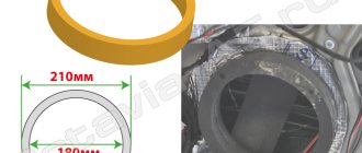
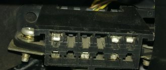
ISO connector is a contact technical device for connecting electrical wires along their groups of eight contacts (16), in two or one rectangular housing.
The brown block connects the wiring for the speaker system and sometimes its control (control of changing radio stations or musical compositions from the steering wheel of a car).
Black block - power (electrical) supply of contacts between the car and the sound-reproducing device.
Sometimes the contacts are combined in one connector, and they are separated into groups in the upper and lower parts of a single housing. ISO is a generally accepted technical standard for goods and services developed by an international organization for standardization.
ACC is a connection that allows you to listen to music and radio without starting the car.
Accelerating Code: Tiles and Barriers
You can gain additional acceleration by using tiling. Tiling divides the threads into equal rectangular subsets or tiles. You determine the appropriate tile size based on your data set and the algorithm that you are coding. For each thread, you have access to the global location of a data element relative to the whole or and access to the local location relative to the tile. Using the local index value simplifies your code because you don't have to write the code to translate index values from global to local. To use tiling, call the on the compute domain in the method, and use a tiled_index object in the lambda expression.
In typical applications, the elements in a tile are related in some way, and the code has to access and keep track of values across the tile. Use the tile_static Keyword keyword and the to accomplish this. A variable that has the tile_static keyword has a scope across an entire tile, and an instance of the variable is created for each tile. You must handle synchronization of tile-thread access to the variable. The stops execution of the current thread until all the threads in the tile have reached the call to . So you can accumulate values across the tile by using tile_static variables. Then you can finish any computations that require access to all the values.
The following diagram represents a two-dimensional array of sampling data that is arranged in tiles.
The following code example uses the sampling data from the previous diagram. The code replaces each value in the tile by the average of the values in the tile.
Features of ISO connectors
Having a single ISO connector standard (electrical characteristics), many automakers, as well as audio equipment companies, can change its external shape at their discretion. That is, if you decide to replace an outdated Hyundai radio with a Mystery multimedia system, first of all, pay attention to the matching iso connection formats.
Also, when installing equipment, you can quite often encounter slight changes in the pinout colors of electrical cords from the standard pinout. Next, we will provide visual descriptions of the pinout of the ISO connector of a standard sample and for individual brands of sound-reproducing equipment (pinout of the ISO connector of the Prology 1715t radio, etc.). Judge for yourself how different they are from each other.
An alternative to ISO connectors are Fakra connections.
Standard form of wiring connections
Upper part of the connector (socket numbers and wiring colors):
- Changing the sound volume when the car is moving - a free-color wire.
- Muting the sound (MUTE) when there is an incoming phone call - a free-color wire.
- Empty nest.
- ACC - power supply 12 volts - wire color yellow.
- Power supply for the radio antenna (12V) - wire color is blue.
- Car radio display backlight - wire color is orange.
- Turning on the ignition - the wire color is red.
- Ground (grounding) - wire color is black.
- Increasing the volume of the right rear speaker - color purple.
- Reducing the volume of the right rear speaker - purple and black.
- Increase the volume of the right front speaker - gray color.
- Reducing the volume of the right front speaker - gray and black.
- Increase the volume of the left front speaker - color white.
- Reducing the volume of the left front speaker - white and black.
- Increase the volume of the left rear speaker - color green.
- Reducing the volume of the left rear speaker - green and black.
The official name of the pinout is ISO 10487 (Euro connector).
Kenwood radio ISO connector pinout
From this manufacturer (Kenwood) we were able to find several differences in the colors of the electrical wires and their purpose for the upper part of the connector block. The lower one, acoustic, fully complies with accepted standards. In order not to repeat ourselves, by default, the contact and option numbers we missed are also standard, as for all car head units. So, in our opinion, the following changes were minor:
- The yellow electrical wire goes to the car battery.
- The red cable goes to the ignition switch (ACC mode).
- Black braided wire - standard (grounding, ground).
- Blue and white wire - regulate power.
- A wire with a color combination of orange and white – adjusts the brightness of the car radio screen backlight (DIMMER).
Pinout problems
As a rule, no unexpected situations arise when connecting a car player via Euro connectors of the ISO 10487 standard. But only under the following conditions!
Your car is equipped with an ISO connection, both on the radio (a standard output for all global brands of this type of equipment) and on the side of the standard car electrics. This means that the previous owner (the car is not new) was not an experimental electrician, that is, he did not change the wires in the connection box or individual fragments of wires at his own discretion.
If the player was manufactured by someone unknown and where, like the connector itself, in such a situation you will need to arm yourself with a digital tester, brush up on your knowledge of electrical engineering and ring all the contact groups yourself. Based on the measurements, you can determine the power values of the wiring.
What types of car radio connectors are there?
Pinout of ISO connectors for car radios
Not so often, but it still happens that almost every car owner is faced with the problem of do-it-yourself installation and subsequent independent connection of the head unit (car radio) to the standard acoustic circuit of his car. It would seem that this could be confusing, because everything is simple there! Yes, this statement is true. But, as experience shows, this confidence lasts until manipulations with the wires begin, during which the “handy” car owner begins to understand that he urgently needs pinout of Euro connectors for car radios, or even better, complete instructions for connecting the car radio.
general information
Do-it-yourself repair of Chinese pioneer car radios
AMP is a technology for accelerated mobile pages, which is developed by independent developers and actively promoted by Google in its search engine. Yandex has not yet joined this initiative, but I am sure that soon they will either implement this standard or come up with something similar in operating principle.
The bottom line is that the site uses special tags, the number and functionality of which are strictly limited. The developer's task is to assemble a hodgepodge of available schemes that will solve the customer's problem.
Pages with AMP rank higher than other queries in search due to the fact that they meet the requirements for fast loading and are adapted for mobile devices.
In fact, all such pages are static or conditionally dynamic, since they allow the use of form submissions, as well as iframes.
Next, I’ll tell you about the main features of AMP.
Markings and types of connectors
To answer your silent question about what kind of connectors there are in car radios, I must answer that most modern car radios are equipped with two standard connectors, designated by the abbreviation “ISO”. Each of these connectors is designed as an eight-pin rectangular plug, sometimes they are combined into one housing (see photo).
Car radio ISO connector pinout
One of the connectors carries “power” circuits, that is, current consumption sources are connected to it, and is designated in the diagrams as a connector under the letter “A” and is colored brown. The second connector is intended for connecting the car’s acoustic system, in other words, speakers. Unlike the previous one, it is made in black and is designated on electrical circuit diagrams as connector “B”.
What connectors do car radios have?
Sometimes there are car radios with three connectors, but this is the exception rather than the rule. The same exception as non-standard connectors, which still have wiring with standard markings and in any case allow you to connect the wires of a standard speaker system with non-standard “connections” in at least two ways. So:
- “Skolkhoz”, namely, cut off the non-standard plug and overlap the wires, which “is not very good”, since over time the twist will become loose due to oxidation/shaking and, in the best case, you will have to do all the work again while simultaneously replacing the fuses.
Pinout of ISO connectors for car radios
- Buy an adapter (the price of which is in no way close to the amount of work that the method described above includes) and, without any problems, decorously/nobly, connect the car radio with other elements of the acoustic circuit of your car.
The choice of adapters at the moment is huge, and it is simply physically impossible for any troubles to arise in the use of this variety.
Car radio ISO connector pinout
Pinout of a standard Euro connector
Let's look at the pinout of the Euro connector on a standard ISO plug - 10478
Upper power connector “A”
As already mentioned, this plug connects the sources and consumers of electrical current from the vehicle’s on-board network.
Despite the fact that it has eight contacts, not all of them can be used in the car radio connection circuit. Let's figure out what the purpose is and what task each of these contacts performs:
- Connectors No. 1, No. 2, No. 3 and No. 6 are rarely used by default in the circuit of a budget car radio. Most often they are used to connect additional functions in more professional versions of the head unit, which significantly increase the comfort of a modern car, while the colors of the wires can be made in various color variations.
For example, among the additional functionality we can highlight the following:
- “ANT” output, which is used in cases where a retractable automatic antenna is installed in the car;
- “REMOTE”, which allows you to connect external amplifiers to the car radio, which means increasing the number of connected speakers (relevant for cars with a large interior, since in a small interior a large number of speakers creates a large load on the hearing organs, which is fraught with negative consequences);
- the “ILLUMINATION” option, which automatically, depending on the speed of the vehicle, controls the light signaling of the car radio - at higher speeds, the brightness of the display decreases and does not distract the driver from the process of driving the vehicle; when the vehicle stops, it returns to its initial parameters, which significantly the extent to which it affects road safety;
- as well as the currently very common “MUTE” option, which is turned on when using a mobile device connected to the car’s speaker system - when a receive/call signal passes through, the car radio automatically activates this output, which leads to a decrease in the volume of the music being played or to a complete shutdown car radio sound;
- Contact number four (indicated on electrical diagrams as “A4”) is responsible for turning on the entire acoustic system of the car. Through a separate fuse, this yellow wire is connected to the ignition switch terminal and is already powered from the battery.
Organizing the connection of the car radio according to this scheme is guaranteed to protect the battery from unauthorized discharge, since turning on the car radio is possible only when the key is turned in the ignition switch.
Reference. The need for this kind of connection arose due to the fact that the cascades of the car audio system continue to consume electrical energy even when turned off, which very often led to battery discharge.
Domestic car enthusiasts have improved the wiring diagrams for car radios as best they can, resorting to both manual toggle switches and installing an automatic relay to turn off the radio when setting the car alarm. But, as we see, it is this connection scheme that has received universal recognition. So:
- The fifth wire (A5), blue, is responsible for connecting the car antenna. It is designed for a maximum output current of 300 microamps, and if this value is exceeded, a large current can damage not only the output amplifier stages, but also the car radio itself as a whole;
- The contact with the positional designation “A7” in red is responsible for delivering voltage to the volatile memory of the car radio. This means that if you accidentally turn it off, all device parameters will be reset/reset to factory settings. The voltage on this wire is 12 volts;
- Well, the last wire of this connector, running in black insulation (A8), as you probably already guessed, is responsible for connecting the device to the ground of the car.
Advice! In order to protect the acoustic circuit, each of the supply wires must be equipped with a fuse-link. If periodic interruptions still occur during the operation of the head unit, then it is recommended to install a capacitor between contacts “A7” and “A8”, the capacity of which is selected experimentally. Essentially, it (the capacitor) will serve as a filter that will smooth out fluctuations in the electrical power circuit of the car's speaker system.
Bottom acoustic connector “B”
As already mentioned, all other peripherals of the car audio system, that is, speakers, are connected through connector “B”. The pinout of the car radio Euro connector under the letter “B” looks like this (see previous photo):
Data filtering
Every AMP page has a state. It can be thought of as an object with a hierarchy of properties. The page state can be changed in event handlers using the AMP.setState function.
Let's add a filter that allows you to display only bikes that are in stock. To do this, we will place a checkbox on the page, by clicking on which we will change the state of the page, assigning a value to the onlyAvailable variable (in accordance with whether the checkbox is selected or not). The name of the variable is arbitrary, it could be called anything
Please note that AMP has its own way of handling events. You can handle multiple events at once, and you can have multiple actions for each event
The data binding mechanism allows you to link page state variables with property values in HTML markup. In order for the AMP library to do this binding, the name of the property that should receive the value must be enclosed in square brackets - . For example, we will add or remove the CSS class 'active' (this is a non-standard class and is set by us) depending on the value of the onlyAvailable variable.
In development mode (#development=1), the page state can be printed to the browser console using the AMP.printState() function;
Now let's add a list of products to the page state. To do this, we will use a separate amp-state component. The component will load data from the same source as amp-list, but re-loading will not occur, since AMP controls data loading and avoids unnecessary requests. In addition, we will add a macro that, when the value of the onlyAvailable variable changes, will filter the list of products.
Now let's use the filtered list as a data source for the amp-list component. To do this, we connect the src property of the component with the filteredBikes macro. We will also connect the height property of the component with the number of elements. This is necessary because the height of the amp-list component will not automatically adjust to the number of elements. In this example, the number 340 is the height of the product card, and 16 is the padding at the top and bottom.
Please note that explicit loading of data by setting the src="https://localhost:3000/api/bikes" property remains. You can't remove it
When loading an AMP page, data binding is not automatically performed for performance reasons. It will be executed only after user actions, such as clicking on a checkbox.
Open the resulting page and check that filtering is working correctly.
Standards 1DIN and 2DIN
The differences between them are the height of the radios. The number 2 in the designation of the 2DIN standard indicates that the height of a double-DIN receiver is 2 times greater than a device made according to the 1DIN standard. The latest radios are now the most popular and widespread. Installation of double-din radios is not possible in every car, since an appropriate seat must be provided on the front panel.
All car radios are divided into two types: with a proprietary connector, most often made in the form of a plug, and located on the rear wall, and with a universal ISO connector. In the first case, you should purchase a proprietary connector for the radio, the pinout of which matches the desired model. If the machine has an ISO socket, then the other end of the proprietary cable should also have an ISO plug. In the second case, the radio is connected directly to the ISO socket located in the car.
When replacing the radio with another one, you should look at the back wall and determine which block is located there. After this, you can decide whether to purchase a proprietary plug or you can connect the device to the machine through an already installed ISO socket. The pinout of the car radio connector is carried out according to the ISO 10487 standard.
How to properly connect to an electronic device
The concept of an interface as we know it today dates back to the 1960s. More precisely, in 1964, when the company developed its legendary IBM System/360 mainframe. It was then that the main tasks of any interface - physical or virtual - were formulated. They were to provide a standard connection for all devices.
Euro connectors
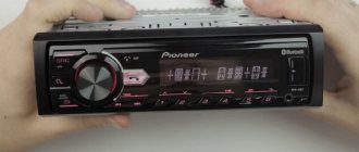
Initially, only a few types of standard inputs could be made to ensure compatibility between products from different manufacturers. This was a PS/2 port for the keyboard, an LPT port for the printer, and a connector for the PCI card. Nowadays, each type of connection has its own standard interface; this approach greatly simplifies the development and sale of any type of device and allows you to understand their built-in capabilities. Here are descriptions of the main communication elements, first of all, the designation of the button on the radio, which are used on the panels of Pioneer and other car radios.
Types of branded connectors
Description of the buttons on the front panel of the radio for control (decoding)
| Button labels | Button function |
| A.F. | Different RDS frequency, automatic search when reception is poor |
| ALL OFF | Everything is off |
| AMS | Music sensor, works on the principle of playing a number of tracks equal to the number of clicks |
| ANG | Panel adjustment |
| ATA | The radio turns on automatically when you turn off and rewind media tracks |
| A.T.T. | Quickly reduces volume |
| BAND | Selecting a radio receiver |
| BEER | Enabling sound when pressing buttons |
| Blank Skip | Skips pauses longer than 8 seconds |
| BMS | Compensates for low frequencies when dropped due to the main device |
| BTM | Remembers the quality frequency of strong stations |
| CLK ADJ | Adjusts time |
| COLOR | Color |
| DISP | Display activation |
| DNPP | Selecting a CD in the changer |
| DNPS | Entering disc names |
| DSP | Activating the sound processor |
| EJECT | Remove the cassette from the cassette receiver or disc |
| EON | Reception of traffic information |
| FUNCTION | Switches the most used functions |
| INTO SCAN | Plays the recording for 10 seconds to search |
| LOS | Looks for stations, skipping with weak reception |
| LOUD | Tone compensation |
| M.RDM | Disc random playback |
| P.I. | Automatic search |
| PI SOUND | Switching to another frequency |
| PI MUTE | Muffled sound |
| POWER | Shutdown |
| PS | Listening to saved settings |
| PTY | Selecting a genre |
| RDS | Search for a station by metadata |
| RDM | Play disc tracks in any order |
| REG | Switching to the frequency of a radio station with RDS |
| Repeat Play | Replaying a track |
| SCAN | Scanning tracks and playing the beginning |
| SEL | Settings |
| SHUFFLE PLAY | Play available music in random order |
| SYSTEM Q | Tracking sound enhancement factors and showing them on the display |
| TA SEEK | Searching for a station with RDS |
| TC | Calling the tuner when rewinding |
ISO pinout
Many new radios increasingly use a Euro connector. It is a rectangular sixteen-pin plug consisting of one or two equal parts. An ISO plug is installed on the car, allowing you to connect any car radio that has the appropriate connector. The ISO pinout does not depend on the radio model equipped with such a connector.
Upper power connector A
It is used to supply current from the vehicle's on-board network, as well as to remove power from an active antenna or amplifier, to mute the sound and supply a backlight control signal. According to the standard, wires are marked by color:
- yellow - direct connection to the vehicle’s battery; it also supplies power to the receiver’s RAM, which provides storage of settings specified by the user;
- red - it supplies the main power;
- black is ground, the negative pole connected to the GU body;
- blue with a white stripe - when the car player is turned on, 12 V is supplied to the active antenna amplifier or the remote control controller of the car audio power amplifier;
- orange - a signal is sent to it from the vehicle’s side light switch to control the backlighting of the keys and display;
- brown - used to mute the sound, for example, while talking on the phone.
It is worth considering that two power supply systems are used. In the first case, the yellow and red wires on the pinout are connected together. The power supply to the radio does not depend on the position of the ignition key.
If you leave the car player on without a protection timer, the car battery may quickly drain.
The second system involves connecting the red wire through the ignition switch, and the yellow wire directly to the on-board network. Thanks to this, the power supply to the radio is connected to the position of the key. When the ignition is off, you can remove or insert the CD. It also keeps the audio system's built-in clock running and saves settings such as sound settings and radio channels.
The pinout of the ISO connector of the radio, intended for power supply, is carried out as follows. Pins 1, 2 and 3 are reserved and are used by some head units to enable additional functions. Pin 4 is connected to the yellow wire, and pin 5 is connected to the blue/white wire. An orange wire is connected to pin 6. Pin 7 is connected to the red wire, and pin 8 is connected to the black wire. This connector is often painted brown.
Bottom speaker connector B
It is used to supply amplified sound from the car player to the speakers. The wires through which alternating current directly flows from the microcircuit are solidly colored, and the wires connected to ground have black stripes. Color marking is carried out as follows:
- the white wire connects to the left front speaker;
- the gray wire connects to the right front speaker;
- the green wire connects to the left rear speaker;
- The purple wire connects to the right rear speaker.
The pinout of the radio chip intended for connecting speakers is done as follows:
- purple wires connect to pins 1 and 2;
- gray - to pins 3 and 4;
- white - to pins 5 and 6;
- green - to pins 7 and 8.
Power connection
Connecting the power supply is the stage at which most mistakes are made when connecting the radio.
To connect power to the radio, it is better to use a separate wiring to the battery, and the wires should have a cross-section of 2-4 sq. mm.
To obtain clean playback after installation, it is better to connect the black and yellow wires to the battery. Install an additional 10-20 A fuse on the yellow wire. The red wire is connected to the ignition circuit.
As a rule, the red and yellow wires are connected together, so the radio operates regardless of the ignition being turned off. But this option has a caveat - the radio will drain the battery, because will remain in sleep mode all the time after shutdown. To eliminate the possibility of the battery being discharged due to this nuance, a separate shutdown button is additionally placed on the red wire, thanks to which the power will turn off automatically when the car is parked for a long time.
Pinout diagrams for radio tape recorders from popular manufacturers
Wiring of linear outputs on a standard radio can be done using two RCA connectors. This option is the most common, since power amplifiers have the same sockets. The pinout of connectors for Pioneer car radios contains from 10 to 20 contacts. Their purpose depends on the model of the multimedia device. For example, in the KEH series, the first pin is the antenna control, the second pin is the voltage from the ignition switch, etc. The speakers are connected to pins 3, 4, 5, 6, 8, 9, 10 and 11.
Pinout of a standard Euro connector
The Euro connector is a standard plug for many modern devices. An ISO plug is installed on the machine, thanks to which it becomes possible to connect any model of radio with the appropriate connector.
Standards 1DIN and 2DIN
The difference between the standards lies in the size of the devices: a 2-din device is 2 times higher than a 1-din device.
The most common are 1-DIN radios, because Installation of higher devices due to the lack of a seat of appropriate size on the front panel of the car is not possible in every car.
There are 2 types of radio tape recorders:
- With proprietary connector. You need to choose a product whose pinout matches the desired car.
- With universal connector. The device connects directly to the ISO socket provided in the car.
Pinout is carried out according to ISO 10487 standard.
Upper power connector A
The connector serves as a connector between sources and consumers of electricity from the on-board network.
Plugs 1, 2, 3, 6 are rarely used in radio circuits of the lower and middle price segments. The elements are used when connecting additional options in higher quality player models. Wire colors may vary.
You should understand the purpose of the contacts:
- ANT. Used with a retractable antenna.
- Remote. Designed for connecting external amplifiers. Thanks to it, you can increase the number of mounted speakers, which is necessary in the interiors of large cars.
- Illumination. Adjusts the brightness of the player screen (the higher the driving speed, the less intense the backlight, so as not to distract the driver).
- Mute. Adjusts the sound of the device.
- A4. Turns the audio system on and off.
This connection scheme allows you to protect the battery from discharge, because turning on the system is possible only when you turn the ignition key, while the acoustic cascades consume electricity even when turned off.
The pinout of the ISO connector of the radio (European) looks like this:
- Connector A5 (blue) is for the antenna. If the permissible current value (300 µA) is exceeded, both the amplifier stages and the entire head unit may break.
- Wire A7 (red) is intended to power the head unit. When it is disabled, the settings are returned to factory settings. Voltage - 12 V.
- Cable A8 (black). Responsible for connecting the speaker system to the car.
To protect the audio system, the wires must be equipped with a fusible link. If interruptions occur in the operation of the player, you should place a capacitor between connectors A7 and A8, which will act as a filter, smoothing out fluctuations in the electrical circuit.
Bottom speaker connector B
The speakers are connected through it as follows:
- Rear right + (purple).
- Rear right - (black and purple).
- Front right + (gray).
- Front left - (black and gray).
- Front left + (white).
- Front left - (black and white).
- Rear left + (green).
- Rear left - (black and green).
Most devices are designed for 4 channels; 8 wires are used for this (2 pieces per speaker).
The sound quality of the system depends on the “flattening”. If you mix up the connectors, the device will not fail, but the radio will not work correctly.
Audio system elements should be connected with cables with a cross-section of 1.5 mm or more. Thicker wires are used on power lines.
Toyota
Adapter from the manufacturer Intro. Responsible for connecting the power supply and acoustic (sound) signal from the ISO connector to the standard radio socket for Japanese-made cars:
- Toyota;
- Lexus;
- Daihatsu.
Renault
ISO adapter from the manufacturer Intro for quickly connecting a modern multimedia system (MMS) or other non-standard device (radio tape recorder) to the place of the factory device. An adapter device of high quality at an affordable price, recommended for installation on cars of the following brands:
- Peugeot;
- Citroen;
- Renaults produced after 2005.
This technical adapter device is a plug for connecting to the standard connector of the player and the connector for the electrical wiring of the car. Without any special tools in a short period of time.
All you need to do is buy an ISO adapter
at an affordable price, and you can independently connect the car radio in the shortest possible time. At the same time, safety from incorrect connections, short circuits and other difficulties is guaranteed.
When you can't do without an ISO adapter
When purchasing a car with medium or higher equipment, the owner receives a standard car radio. Often its functions are limited to playing CDs, MP3 files, and listening to radio stations. The presence of a USB interface is much less common; only premium cars are equipped with a navigation system that allows you to display images from the rear view camera. Unfortunately, not everyone has the opportunity to buy a premium car; in other cases, the car radio is either completely simple or simply absent. The problem is solved by purchasing and installing one of the speaker systems offered on the modern market.
But here an additional difficulty arises - a warranty is provided for a new car, but it is preserved only if the owner adheres to all the rules for operating the vehicle. One of them is not to tamper with the car's electrical wiring. Therefore, many dealers prohibit installing radios and other equipment in third-party service centers. The problem is exacerbated by the fact that many car manufacturers use their own mounts, connectors and form factors, resulting in additional difficulties in installing the speaker system.
Methods for connecting a new radio
If the driver decides to replace the standard car radio, then he has two options:
- Cut off the “original” connectors and twist and solder the wires, and then insulate them. If, after solving the problem in this way, you contact the dealer to take advantage of the car’s warranty service, the probability of receiving a refusal will approach 100%. In addition, in the future it will be difficult to return everything to its original place. It is difficult to expect high quality from the resulting connection - when there is frost outside, the wires become tanned, and the twisting encounters vibration while driving, as a result of which the contact may disappear or periodically disappear.
- Select and purchase the appropriate ISO adapter
. This is the optimal solution to the problem - there is no need to make any changes to the car wiring, or damage the standard connectors. All that is required is to remove the plugs or the “original” car radio, and then install two adapters - for the antenna and for the electrics. This will take no more than 10 minutes! And if the driver has to go to a dealer’s service station, he can always return the standard radio.
The AvtoProfi store offers adapters for various car models. A wide range of adapters will allow everyone to choose the most suitable product that will facilitate the installation of a stereo system. And if you need additional help with choosing a product or making a payment, our employees will be happy to provide it.
A little theory: the pinout of the ISO connector of the radio is determined by the functionality of the contacts in the plugs, in accordance with their numbering. ISO radio connector is a connector for connecting a car's standard radio, certified according to international standards.
When trying to independently replace, for example, a car player from Pioneer with a JVC, car owners are faced with a situation where the wires in the plug are mixed up or do not even fit the shape of the connectors. In order to solve this issue, you need to buy an ISO plug, which is sold at any auto parts store. After that, pinout the head unit connector according to the diagram.
Pinouts for various brands of cars and radios
The wiring of the linear outputs on the standard radio depends on the make of the car and the head unit.
Before pinouting the connectors of the car radio, you must read the information presented on the cover of the device and in the instructions for it.
Toyota
For a standard plug: 1 - A+, 2 - GND, 3 - BAT+, 4 - backlight, 5 - antenna adjustment, 9-16 - speakers (RR+, RR-, RF+, RF-, LF+, LF-, LR+, LR -).
Universal connector for most models: 1 - ANT, 3 - linear output LR, 4 - GND linear outputs, 5 - linear output RR, 6 - CD in LCH, 7 - CD in GND, 8 - CD in RCH, 9 - CD reset , 10 — CD clock out, 11 — CD DSPL select, 12 — CD data out, 13 — CD clock in, 14 — CD data in, 16 — A+, 17 — GND, 18 — ANT GND, 22-27 and 29- 30 — speakers (LF-, LR+, RF-, RR+, LF+, LR-, RF+, RR-), 28 — CD mute, 31 — ANT CONT, 32 — CD ACC CONT, 33 — AMP CONT, 34 — B UP .
Nissan
Standard circuit: 1-6 - speakers (LR+, RR+, LR-, RR-, LF+, RF+), 7 - A+, 8 - backlight, 9 - BAT+, 10 - LF- speaker, 11 - RF- speaker, 12 - antenna control, 13 - GND.
Honda
Standard connector: 1 - RR+ speaker, 2 - LR+ speaker, 3 - backlight, 4 - BAT+, 5 - A+, 6 - antenna control, 7-10 - speakers (LF+, RF+, RR-, LR-), 13 - GND , 14-15 - speakers (LF-, RF-).
Universal connectors: 1 - A+, 2 - BAT+, 3 - GND, 4 - empty, 5-12 - speakers (RR+, RR-, LF+, LF-, RF+, RF-, LR+, LR-).
Alpine
Alpine TDE-7823W: 1 - BAT+, 2-5 - speakers (LR-, LR+, RR-, RR+), 7 - amplifier control, 8 - antenna adjustment, 9 - GND, 10-13 - speakers (LF-, LF+ , RF-, RF+), 16 - A+.
Alpine 7190M: 2 - amplifier control, 8 - GND linear outputs, 9-10 linear outputs (R, L), 13 - antenna, 27-28 - speakers (LR+, LR- and LF-, LF+), 29 - GND, 31 - BAT+, 32 - A+, 34-36 - speakers (RR+, RR- and RF-, RF+).
Mitsubishi
For all models: 1-2 — speakers (RR+, LR+), 3 — antenna, 4 — backlight+, 5-8 — speakers (LF+, RF+, RR-, LR-), 10 — A+, 11- BAT+, 12 — backlight, 13-14 — speakers (LF-, RF-), GND — connector rim.
Kenwood KDC KRC
There are several options for pinout of the radio chip from this manufacturer, depending on the model of the device:
- KDC5040R and others: 1 - GND, 2 - A+, 3 - antenna, 5-8 - speakers (RF+, RF-, LF-, LF+), 9 - BAT+, 10 - backlight, 11 - TEL mute, 12 - EXT AMPL CONT, 13-16 - speakers (RR+, RR-, LR-, LR+).
- KRC155D: 1 - GND, 3 - A+, 5 - BAT+, 8-9 - speakers.
- KDC84R and others: 1 - input A, 2 - GND input A, 7-10 - linear outputs (L, R, R, L), 11 - input A, 17-20 - GND linear output (L, R, R , L), 25 - GND, 26 - A+, 27 - amplifier, 33 - BAT+, 34 - backlight.
- KRC752R: 1 - ANT GND, 4 and 28 - output L, 5, 18, 27 and 39 - GND outputs (L, R, L, R, respectively), 8 - backlight, 9 - BAT, 10-13 - speakers (LR -, LR+, LF+, LF-), 14 — ANT, 17 and 40 — output R, 20 — antenna, 21 — A+, 22 — GND, 23-26 — speakers (RR-, RR+, RF+, RF-), 36 and 48 - phone interface.
Shaping and Indexing Data: index and extent
You must define the data values and declare the shape of the data before you can run the kernel code. All data is defined to be an array (rectangular), and you can define the array to have any rank (number of dimensions). The data can be any size in any of the dimensions.
index Class
The index Class specifies a location in the or object by encapsulating the offset from the origin in each dimension into one object. When you access a location in the array, you pass an object to the indexing operator, , instead of a list of integer indexes. You can access the elements in each dimension by using the or the .
The following example creates a one-dimensional index that specifies the third element in a one-dimensional object. The index is used to print the third element in the object. The output is 3.
The following example creates a two-dimensional index that specifies the element where the row = 1 and the column = 2 in a two-dimensional object. The first parameter in the constructor is the row component, and the second parameter is the column component. The output is 6.
The following example creates a three-dimensional index that specifies the element where the depth = 0, the row = 1, and the column = 3 in a three-dimensional object. Notice that the first parameter is the depth component, the second parameter is the row component, and the third parameter is the column component. The output is 8.
extent Class
The extent Class specifies the length of the data in each dimension of the or object. You can create an extent and use it to create an or object. You can also retrieve the extent of an existing or object. The following example prints the length of the extent in each dimension of an object.
The following example creates an object that has the same dimensions as the object in the previous example, but this example uses an object instead of using explicit parameters in the constructor.