Purpose of valve guides
This element is the main one and the excellent performance of the “seat-valve plate” union directly depends on it.
The design of the part and the metal from which it is made are designed to ensure its operation at high speeds with regular temperature effects and limited access of lubricants to the space between the valve and the bushing.
Signs of faulty guide sleeves
Wear of valve guides can be easily and quickly determined by the vehicle owner. The main symptom of this malfunction is an increase in engine oil consumption.
The first thing to check when engine oil consumption increases is the car's engine valves. Another sign of a malfunction may be a characteristic motor noise in the head area. The easiest way to check this is to open the hood of the car, start the engine and listen carefully. If a strange and unusual noise is noticeable against the background of the engine operation, then it is worth diagnosing the valves and guide bushings.
What causes valve bushings to wear out?
The above factors influence the fact that over time, the valve guides are subject to wear and their alignment with the valve tappet changes.
This leads to the guide being broken and the valve starting to dangle, which ultimately leads to damage to the seat chamfer. From this you can expect the valves to burn out and their seats to be replaced.
In addition, due to the “looseness” of the valve, when the guide is broken, the operation of the valve seals is disrupted. As a result, they do not retain oil due to valve misalignment.
The result is that lubricant gets into the cylinders, which leads to an increase in carbon deposits on the valves. The amount of harmful substances released into the exhaust system will also increase and the catalyst may fail prematurely. Accordingly, replacing the seals in such a situation will not correct it in any way.
Causes of parts failure and their consequences
A characteristic feature of the guide elements is that they do not fail at once, but wear out gradually. The lifespan of parts on budget cars ranges from 180 to 300 thousand km, and on more expensive foreign cars it can reach 1 million km. The wear process is influenced by several factors that can accelerate it:
- the quality of the motor oil used and the timeliness of its replacement;
- temperature conditions of the power unit, the more often the engine overheats, the faster the rubbing surfaces wear out;
- the quality of the fuel and combustible mixture, whose vapors penetrate into any leaks and contribute to the process of slow destruction of parts.
Carbon deposits on the rod destroy the bushing quite quickly
Note. The working life of all elements of the gas distribution mechanism is also affected by the serviceability of the power supply and ignition system. When, as a result of a malfunction, pops occur in the fuel or exhaust manifold, the lubricant between the valve-bushing pair is washed off with unburned gasoline, which is why the mechanism runs “dry” for several seconds.
A worn part is characterized by a “broken” internal hole, as a result of which the valve stem begins to move too freely in it, and then play appears. The rod warps during operation, and the plate does not fit well with the seat, the tightness of the interface is gradually lost. Gases escape from the combustion chamber into the mechanism, and oil enters from above, resulting in the formation of carbon deposits. It also accelerates wear, quickly rendering the part completely unusable.
Instructions for diagnosing valve guides
When an engine is repaired, in addition to updating the crankshaft, it is also necessary to repair the cylinder head.
- Because future compression in the cylinders also depends on it.
- Usually, during cylinder head repairs, car owners grind the valves and do not attach much importance to loose bushings.
- Since, when the gap between the valve pusher and the bushing exceeds the permissible parameters, then grinding in the valves will not give the desired result.
Replacing valve seats with your own hands - we analyze the specifics of the work
This operation is performed in two ways. The first one is rough, but the simplest and fastest. It is carried out quite primitively: an old valve is welded onto a worn seat ring, and then the ring is simply knocked out with a hammer from its regular place in the cylinder head; by the way, it can be damaged, which is very undesirable. Next comes the process of pressing in the new one. The soft method is much more complicated, however, it can be done in your garage without the intervention of expensive equipment. The saddle in this method is carefully turned on a machine. After this, the seat is cleaned and also ground.
Reliable pressing occurs when the new seat is cooled and the cylinder head is heated; only after such work can the mechanism be guaranteed to be used reliably. The whole difficulty of the method lies in heating and cooling; you will first need to think about how you will do this. If the saddle is not completely worn, it can be adjusted. When using a cutter for repairs, mainly several cutters with different angles are used. The first coarse nozzle is put on the mandrel, after which the seat is prepared or trimmed in a circular motion; countersinks can be used in the same way for trimming valve seats.
Next we proceed to grinding in, it is carried out using a special device designed for this, at the end of which there is a cone. Abrasive powder or paste is applied to the seat chamfer. Grinding is carried out until friction produces minimal sound and grinding noise. Remains of paste or powder are carefully removed. The quality of the work can be assessed by turning the head over and pouring kerosene into it; if it does not leak out, it means we did a great job.
Sources:
https://cartore.ru/3026-zamena-vtulok-klapanov.html https://kalina-2.ru/remont-vaz/razmery-napravljajushhih-vtulok-klapanov-vaz-2108 https://portalmashin.ru/ lada/zamena-klapanov-lada-2108-vaz-2108.html
Peculiarities
A considerable part of the parts have a special collar on the outside for their necessary vertical fixation in the head. In the case when the bushing is smooth, its installation is carried out with a special mandrel.
On intake valves, the parts in question must not protrude in order to avoid increasing the aerodynamics of the valve resistance. In the exhaust, the bushings must completely hide the valve post so that it is not exposed to high temperatures and heat is better removed from it.
General arrangement of cylinder head bushings
On modern cars, valve heads are made of special alloys.
Valve guides for VAZ 2106
On the VAZ 2109, for example, the guides are made of wear-resistant material and are pressed into the head at high temperatures, so changing them is quite difficult. But it is still necessary to carry out the replacement procedure, since the bushing, despite its strength, wears out over time, losing its tightness. The problem is especially acute for engines with a large number of valves.
Wear measurement
- Determination using a micrometer and bore gauge. They can be used to measure the inner diameter of the guides and the outer diameter of the valve lifter. By comparing these two values and calculating the difference, you can find out how much they correspond to the parameters necessary for normal operation. When measurements are taken, it is necessary to thoroughly clean the parts from dirt and carbon deposits.
- Detection of wear using a dial indicator. Using this tool, diameter readings are taken and if the obtained value is greater than the permissible value, a new valve is taken and a measurement is taken. If in this case the value is outside the limits, then these elements must be replaced.
Tools and materials
Replacement of guide bushings is carried out using the following tools:
- hammer;
- sweeps at 8.022 and 8.028;
- mandrel for pressing out and pressing in bushings.
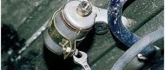
The bushings are changed using a stepped mandrel - a brass or bronze tool. It rests against the guide sleeve, after which it is knocked out with a hammer blow. This method of pressing out does not harm the cylinder head as much as using a regular hammer and chisel. A special puller is used not only to remove bushings, but also to replace them.
Stepped mandrel used for pressing out VAZ 2106 guide bushings
The best tool for replacing guide bushings is a push-out puller. Such devices allow you to remove valve bushings without damaging the seating plane on the cylinder head. The presence of this tool allows you to avoid scoring and other cylinder head defects that may appear when using a mandrel and hammer.
Puller-extruder for guide bushings VAZ 2106 - universal tool
Dismantling
In order to remove the bushings from their seats, it is necessary to heat the cylinder head to 100 degrees Celsius.
This is done because the head has a greater expansion coefficient and when heated, the tension between the bushings and the cylinder head will decrease, which will make it easy to knock them out of their seats using a hammer or sledgehammer.
During the dismantling process, it is recommended to use a special drift. It will give precision pressing without distortions. Those car enthusiasts who professionally carry out repairs purchase pneumatic hammers and special attachments for such procedures.
Replacement process
As mentioned above, a special attachment is required to remove and install the guides. Let's look at what it is and how to use it.
Description of the tutorial
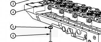
The mandrel for removing and installing the guide consists of two parts. The first part is a rod of a certain length, machined on a lathe and having different diameters in certain places. The largest diameter of the rod occupies its main length and is 18 mm. The rod is held by hand by this part, and it limits the rod from slipping to the other side when removing the bushing, which will protect the surface of the block head from being hit with a hammer. The diameter of the second part of the rod is equal to the diameter of the sleeve. The length of this part is equal to the depth of the hole in which the sleeve is located. The third part of the stem is the shortest - its diameter corresponds to the internal diameter of the valve stem (the diameter of the inner surface of the guide). Its purpose is to ensure that when knocking out the bushing, the direction of the rod strictly corresponds to the direction of the bushing and does not create a distortion of the rod when hitting it with a hammer.
This is interesting: Basics of power steering. Causes of loss of performance
The second part of the rod is similar to a socket head. It is distinguished from a socket head by the absence of edges inside (a cylindrical hole with a diameter and length equal to the diameter and length of the upper part of the guide). In the upper part of the head there is a hole with a diameter equal to the inner diameter of the sleeve and the outer size of the rod on the working side. As can be seen from the description of the mandrel, finding a replacement for it using available materials is not so difficult. To do this, at a minimum, you will need a cylindrical rod of a convenient length, the diameter of which on one side is equal to the outer diameter of the sleeve. As an attachment, you can use an old oil pump rod from a VAZ, after grinding off the gear.
To install the guide in place, use a socket of the appropriate diameter or a suitable hollow tube. Further in the text the terms “mandrel”, “rod”, “head” will be used, implying both a special mandrel and suitable available means.
The process of removing a worn guide and installing a new one
To remove the bushing, turn the cylinder head over with the working part facing up. Next, take the stem, insert it into the valve hole and carefully press it out with a hammer.
In this process, the accuracy of the blow is important. If you hit the surface of the cylinder head with a hammer, this will disrupt the plane of the cylinder head. To knock out the bushing, the blow must be strong, and for this it is better to use a heavy hammer. To install a new bushing, place the cylinder head on the surface in the position in which it is placed on the engine. Then take the new bushing, coat the outer surface with oil and install it in the desired hole.
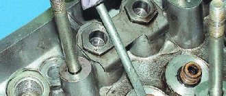
Next, put the head on it and insert the rod. Gently hitting the top of the rod with a hammer, press the bushing guide into place. When installing, pay attention that the selected means do not touch the top of the oil seal seat (marked with arrow 1), since upon impact the seat will be deformed or a piece will break off from it. The head should rest against the base of the oil seal seat (marked with arrow 2).
There are no problems with removing and installing the guide bushing. This is a simple procedure that requires certain knowledge, accuracy and precision when working.
Installation
Initially, before installation, you need to know the parameters of the actual tension. To determine it, it is necessary to measure the diameter of the seat and the outer diameter of the sleeve.
- The difference in values between them should not be more than 0.03 - 0.05 millimeters.
- It follows from this that when the diameter of the sleeve is significantly smaller in contrast to the seat, it is necessary to select a product of a different size. Otherwise, you can increase the diameter of the socket on the drilling machine.
- Before installing the parts into the mounting socket, you need to warm up the cylinder head to the above-mentioned temperature. And before installation, it is advisable to cool them in liquid nitrogen to reduce their size, which will ensure their smooth pressing. This will also protect parts from unwanted damage during installation.
- If you don't have liquid nitrogen on hand, you can cool the parts in the freezer.
In addition, it is recommended to lubricate the parts with oil.
Installation of parts in place occurs in the same way as dismantling. The tool used is also the same. Afterwards, through a series of blows, the bushing is hammered into place.
Rear wheel installation process
It will help to correctly install the rear wheel by strictly following the reverse order of dismantling. To do this, we adhere to the following algorithm:
The chain is put on the smallest sprocket size. After this, the wheel is inserted into the bicycle body mount.
It is important to ensure that the axle is finally secured in the grooves of the frame. The next step is to tighten the nuts or eccentrics with the necessary force so that the wheel does not later jump out of the frame. If the bike uses rim brakes, this is a further step. The main thing is to fasten them strictly in the reverse order.
Otherwise, the trip will not be so safe.
Upon completion of the wheel installation, it is necessary to conduct a small test of the bicycle in order to check the functionality of all parts. Do not neglect the maintenance of all parts and mechanisms of the bicycle. After all, this is the only way to extend their service life.
Last stage of installation
Often valves are not included in new products. This is due to a decrease in their internal diameter after pressing. In order to correct the current situation, you need to apply sweeps.
- They are used in increments until the valve fits normally into the guide.
- Accordingly, you need to monitor the dimensions after using each scan.
- It is recommended to buy diamond-coated reamers, since ordinary steel ones very quickly lose their functionality.
Timely replacement saves a considerable amount of time and money.
How to press out old bushings
The technology for pressing out old bushings varies, but the impact method is more often used.
From the seat side, a brass or bronze mandrel is installed on the bushing, which is struck with a hammer. In order not to damage the seat in the head, the mandrel must be stepped: along the smaller diameter it fits into the bushing to a depth of 30-40 mm with a small gap, and at the larger diameter it freely passes through the seat in the cylinder head. Bronze bushings do not create big problems when pressed out; they are usually installed in the head with a slight interference fit. When pressing out “solid” bushings, it is advisable to heat the head to 150 degrees to slightly reduce the interference. It is better to heat the head in an electric oven, but in a garage a household electric stove will do. If none of the methods allows you to press out the bushing because the fit in the socket is too tight, you have to drill it out. An ordinary drilling machine is quite suitable, but when using a hand-held electric drill, distortions and damage to the seat are inevitable. By the way, it is better not to drill out the part completely. With a wall thickness of about 1 mm, the remaining part can be knocked out without much difficulty.
Photo instructions for replacing valve guides
The final stage: grinding in the valves
Final processing of the joint between the valve and the seat - valve grinding.
In professional repairs, this operation is practically not used. If the valve seat and chamfer are precisely machined, then lapping is not necessary, but even harmful. It’s a different matter when manually processing parts with cutters and cutting heads. Surfaces after repair may not have an ideal shape and roughness. Lapping is needed not so much for processing as for controlling the quality of the mating. If you wipe the ground surfaces dry and turn the valve in both directions several times, pressing it against the seat, a shiny line will appear on the chamfers of the parts. It will turn out closed, running along the entire circumference - everything is done correctly and the fit is good.
Tightening torques for CORSA C
Approximate tightening torque values
Z10XE, Z10XEP
| Nm | |
| Exhaust manifold on cylinder head | 20. |
| Exhaust pipe on exhaust manifold | 25 |
| Exhaust gas recirculation valve on cylinder head | 8 |
| Exhaust manifold shield on exhaust manifold | 8 |
| Axle shaft on the wheel hub | |
| Motor holder adapter right on motor holder right | 60 Nm + 30° + 15° |
| Engine shock absorber adapter left on gearbox holder | 80 Nm |
| Left engine shock absorber adapter on left engine shock absorber | 80 Nm + 45° + 15° |
| Starter on cylinder block | 25 |
| Suction pipe on the throttle valve module | 7 |
| Coolant pump cover | 8 |
| Oil filter housing cover on oil filter housing | 10 |
| Rear anti-rotation stopper on rear anti-rotation stopper holder | 80 |
| Anti-rotation stop at the rear on the front axle housing | 80 |
| Throttle valve module on intake manifold | 7 |
| Intake manifold on cylinder head | 10 |
| Threaded fitting on coolant pump cover | 10 |
| Wishbone joint on steering knuckle | 60. |
| Guide bar on cylinder block | 8 |
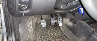
| Accelerator pedal (pedal position sensor) on the end panel | 9 |
| Generator on timing case and cylinder block | 35 |
| Gearbox holder on gearbox | 60 |
| Dampener bar on the cylinder head | 8 |
| Anti-spinning holder on the rear of the gearbox | 80 Nm + 45° + 15° |
| Crankshaft pulse generator on the crankshaft support | 8 |
| Crankshaft pulse drive on crankshaft | 15 |
| Coolant pump serpentine belt pulley on coolant pump | 20 |
| Crankshaft serpentine belt pulley on crankshaft hub | 8 |
| Poly V-belt tensioner on timing case (M10) | 55 |
| Poly V-belt tensioner on timing case (M8) | 20 |
| Chain tensioner on cylinder head | 8 |
| Intermediate steering spindle clamping screw on steering gear | 22 |
| Knock sensor on the cylinder block | 20 |
| Fuel distributor pipe on the intake manifold | 6 |
| Radiator holder at the top of the front | 25 |
| Radiator holder at the bottom of the front axle housing | 15 |
| Coolant pump on timing case | 8 |
| Crankshaft support on cylinder block (M6) | 10 Nm + 45° + 15° |
| Crankshaft support on cylinder block (M8) | 25 Nm + 45° + 15° |
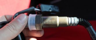
| Heated lambda sensor for regulating the fuel mixture on the exhaust manifold | 40 |
| Lambda catalyst monitoring sensor on the front exhaust pipe | 40 |
| Fan housing on radiator | 5 |
| Fan motor on fan housing | 5 |
| Engine damping block on the left on the longitudinal beam | 25 |
| Engine shock-absorbing unit on the right on the longitudinal beam | 40 |
| Engine holder on the right side of the timing case | 60 |
| Engine transport bracket on the cylinder head | 20 |
| Crankshaft hub on crankshaft | 150 Nm + 45° |
| Camshaft bearing cover on cylinder head | 8 |
| Camshaft drive gear on camshaft | 50 Nm + 60° |
| Camshaft sensor on timing case | 6 |
| Oil drain plug on the oil pan | 10 |
| Oil pressure switch on cylinder head | 20 |
| Oil filter housing on cylinder block | 20 |
| Oil dipstick guide tube on exhaust manifold | 8 |
| Oil pump cover on timing case | 8 |
| Oil suction line on the oil pan | 14 |
| Oil deflector on crankshaft support | 8 |
| Oil pan on gearbox (M10) | 40 |
| Oil pan on crankshaft support and timing case | 10 |
| Connecting rod bearing cap on connecting rod | 10 Nm + 60° + 15° (M6) |
| From engine number 19P13554 (13 Nm + 60° + 15°) (M6.5) | |
| Wheel on wheel hub | 110 |
| Exhaust gas recirculation pipe on the exhaust gas recirculation valve | 8 |
| Manual gearbox on engine (M10) | 40 |
| Manual gearbox on engine (M12) | 60 |
| Hose clamps in the air system | 3,5 |
| Flywheel on crankshaft | 35 Nm + 30° |
| Coolant temperature sensor on the coolant pump cover | 18 |
| Tension bar on cylinder block | 20 |
| Tie rod on steering knuckle | 35 10). |
| Timing housing on cylinder block, crankshaft support (M10) | 35 |
| Timing housing on cylinder head, cylinder block, crankshaft support (M6) | 8 |
| Thermostat housing (coolant pipe) on the coolant pump | 8 |
| Compressor on cylinder block and timing case | 20 |
| Condenser on the radiator | 5 |
| Screw plug on coolant pump | 15 |
| Threaded plug for chain tensioner on timing case | 50 |
| Crankshaft support screw plug | 50 |
| Oil pressure control valve screw plug | 50 |
| Threaded plug for the primary fill lubrication channel on the timing case | 50 |
| Front axle housing on body | 90 Nm + 45° + 15°11)12) |
| Spark plugs on the cylinder head | 25 |
| Ignition module on cylinder head | 8 |
| Cylinder head on cylinder block | 25 Nm + 60° + 60° + 60° 11) |
| Cylinder head cover on cylinder head | 8 |
) Use new fastening nuts ) Tighten the castle nut to 120 Nm, then loosen until it can be turned by hand. Tighten the castle nut again to 20 Nm = 90° and secure with a new cotter pin ) Installation and removal of fastening screws or nuts using an impact driver/wrench is not permitted ) Use new fastening nuts ) Use a new fastening screw ) Use a new fastening screw ) Insert with special lubricant ) Use new mounting screw ) Use new mounting screws ) Use new mounting nuts ) Use new mounting screws ) Mounting or removing mounting screws or nuts using an impact driver/wrench is not permitted
Approximate tightening torque values
Z12XE, Z12XEP, Z14XEP
| Nm | |
| Exhaust manifold on cylinder head (Z 12 XE, Z 14 XEP) | 15 Nm, wait 30 s and then 15 Nm again |
| Exhaust manifold on cylinder head (Z 12 XEP, Z 14 XEP-Combo) | 20 Nm (2 passes) |
| Front exhaust pipe on exhaust manifold | 20 |
| Exhaust gas recirculation valve on cylinder head | 8 |
| Exhaust manifold screen on exhaust manifold | 8 |
| Axle shaft on the wheel hub | |
| Right motor holder adapter to right motor holder | 60 Nm + 30° + 15° |
| Adapter for left engine shock absorber on gearbox holder | 80 Nm |
| Left engine shock absorber block adapter to left engine shock absorber block | 80 Nm + 45° + 15° |
| Starter on cylinder block | 25 |
| Inlet pipe on throttle module | 7 |
| Coolant pump cover | 8 |
| Oil filter housing cover on oil filter housing | 10 |
| Anti-rotation backgauge on anti-rotation backgauge holder | 80 |
| Rear anti-rotation stop on the front axle housing | 80 |
| Throttle valve module on intake manifold | 7 |
| Intake manifold on cylinder head | 10 |
| Threaded fitting on coolant pump cover | 10 |
| Control arm guide joint on steering knuckle | 60 |
| Guide bar on cylinder block | 8 |
| Accelerator pedal (pedal position sensor) on the end panel | 9 |
| Generator on timing case and cylinder block | 35 |
| Gearbox holder on gearbox | 60 |
| Dampener bar on the cylinder head | 8 |
| Rear anti-spinning support holder on gearbox | 80 Nm + 45° + 15° |
| Crankshaft pulse generator on the crankshaft bearing bridge | 8 |
| Crankshaft pulse drive on crankshaft | 15 |
| Coolant pump serpentine belt pulley on coolant pump | 20 |
| Crankshaft serpentine belt pulley on crankshaft hub | 8 |
| Poly V-belt tensioner on timing case (M10) | 55 |
| Poly V-belt tensioner on timing case (M8) | 20 |
| Chain tensioner on cylinder head | 8 |
| Intermediate steering spindle clamping screw on steering gear | 22 |
| Knock sensor on the cylinder block | 20 |
| Fuel distributor pipe on the intake manifold | 6 |
| Upper radiator holder on the front of the structure | 25 |
| Lower radiator holder on the front axle housing | 15 |
| Coolant pump on timing case | 8 |
| Bearing bridge of the crankshaft on the cylinder block (M6) | 10 Nm + 45° + 15° |
| Bearing bridge of the crankshaft on the cylinder block (M8) | 25 Nm + 45° + 15° |
| Lambda sensor, fuel mixture control, with heating on the exhaust manifold | 40 |
| Lambda sensor, catalyst control on the front exhaust pipe | 40 |
| Fan housing on radiator | 5 |
| Fan motor on fan housing | 5 |
| Left engine damping block on longitudinal beam | 25 |
| Right engine damping block on longitudinal beam | 40 |
| Right engine holder on timing case | 60 |
| Engine transport bracket on the cylinder head | 20 |
| Crankshaft hub on crankshaft | 150 Nm + 45° |
| Camshaft bearing cover on cylinder head | 8 |
| Camshaft drive gear on camshaft | 50 Nm + 60° |
| Camshaft sensor on timing case | 6 |
| Oil drain plug on the oil pan | 10 |
| Oil pressure switch on cylinder head | 20 |
| Oil filter housing on cylinder block | 20 |
| Oil dipstick guide pipe on exhaust manifold | 8 |
| Oil pump cover on timing case | 8 |
| Oil suction line on the oil pan | 14 |
| Oil deflector on the bearing bridge of the crankshaft | 8 |
| Oil pan on gearbox (M10) | 40 |
| Oil pan on the crankshaft bearing bridge and timing case | 10 |
| Connecting rod bearing cap on connecting rod | 10 Nm + 60° + 15° (M6) From engine number 19P13554 13 Nm + 60° +15° (M6.5) |
| Wheel on wheel hub | 110 |
| Exhaust gas recirculation pipe on the exhaust gas recirculation valve | 8 |
| Manual gearbox on the engine (M10) | 40 |
| Manual gearbox on the engine (M12) | 60 |
| Hose clamps in the air intake system | 3,5 |
| Flywheel on crankshaft | 35 Nm + 30° |
| Coolant temperature sensor on the coolant pump cover | 18 |
| Tension bar on cylinder block | 20 |
| Tie rod on steering knuckle | 35 10) |
| Timing housing on cylinder block, crankshaft bearing bridge (M10) | 35 |
| Timing housing on cylinder head, cylinder block, crankshaft bearing bridge (M6) | 8 |
| Thermostat housing (coolant pipe) on the coolant pump | 8 |
| Compressor on cylinder block and timing case | 20 |
| Condenser on the radiator | 5 |
| Screw plug on coolant pump | 15 |
| Chain tensioner screw plug on timing case | 50 |
| Crankshaft bearing bridge screw plug | 50 |
| Oil pressure control valve screw plug | 50 |
| Screw plug for initial filling of the lubrication channel on the timing case | 50 |
| Front axle housing on body | 90 Nm + 45° + 15° 11)12) |
| Spark plugs on the cylinder head | 25 |
| Ignition module on cylinder head | 8 |
| Cylinder head on cylinder block | 25 Nm + 60° + 60° + 60° 11) |
| Cylinder head cover on cylinder head | 8 |
) Use new fastening nut(s) ) Tighten the castle nut to 120 Nm, then loosen until it can be turned by hand. Retighten the castle nut to 20 Nm + 90° and secure with a new cotter pin ) Do not use an impact wrench to install or remove the mounting screws and nuts ) Use a new mounting nut(s) ) Use a new mounting screw ) Use a new mounting nut(s) ) Install with special lubricant ) Use new mounting screw ) Use new mounting screw(s) ) Use new mounting nut(s). ) Use new mounting screw(s) ) Do not install or remove mounting screws or nuts with an impact wrench